Sign In
Upload
Download
Table of Contents
Contents
Add to my manuals
Delete from my manuals
Share
URL of this page:
HTML Link:
Bookmark this page
Add
Manual will be automatically added to "My Manuals"
Print this page
×
Bookmark added
×
Added to my manuals
Manuals
Brands
IDEC Manuals
Other
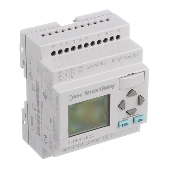
FL1E-H12RCA
User manual
IDEC FL1E-H12RCA User Manual
Fl1e series. smartrelay
Hide thumbs
1
2
3
4
5
6
7
8
Table Of Contents
9
10
11
12
13
14
15
16
17
18
19
20
21
22
23
24
25
26
27
28
29
30
31
32
33
34
35
36
37
38
39
40
41
42
43
44
45
46
47
48
49
50
51
52
53
54
55
56
57
58
59
60
61
62
63
64
65
66
67
68
69
70
71
72
73
74
75
76
77
78
79
80
81
82
83
84
85
86
87
88
89
90
91
92
93
94
95
96
97
98
99
100
101
102
103
104
105
106
107
108
109
110
111
112
113
114
115
116
117
118
119
120
121
122
123
124
125
126
127
128
129
130
131
132
133
134
135
136
137
138
139
140
141
142
143
144
145
146
147
148
149
150
151
152
153
154
155
156
157
158
159
160
161
162
163
164
165
166
167
168
169
170
171
172
173
174
175
176
177
178
179
180
181
182
183
184
185
186
187
188
189
190
191
192
193
194
195
196
197
198
199
200
201
202
203
204
205
206
207
208
209
210
211
212
213
214
215
216
217
218
219
220
221
222
223
224
225
226
227
228
229
230
231
232
233
234
235
236
237
238
239
240
241
242
243
244
245
246
247
248
249
250
251
252
253
254
255
256
257
258
259
260
261
262
263
264
265
266
267
268
269
270
271
272
273
274
275
276
277
278
279
280
281
282
283
284
285
286
287
288
289
290
291
292
293
294
295
296
297
298
299
300
301
302
303
304
305
306
307
308
309
310
311
312
313
314
315
316
317
318
319
320
321
322
323
324
325
326
327
328
329
330
331
332
333
334
335
336
337
338
339
340
341
342
343
344
345
346
347
348
349
350
351
352
353
354
355
356
page
of
356
Go
/
356
Contents
Table of Contents
Bookmarks
Table of Contents
Table of Contents
1 Getting Started with IDEC Smartrelay
2 IDEC Smartrelay Installation and Wiring
Modular IDEC Smartrelay Setup
Maximum Setup
Setup with Different Voltage Classes
Compatibility
Installing/Removing IDEC Smartrelay
DIN Rail Mounting
Wall-Mounting
Mounting the Text Display
Wiring IDEC Smartrelay
Connecting the Power Supply
Connecting the Text Display Power Supply
Connecting IDEC Smartrelay Inputs
Connecting Outputs
Connecting the as Interface Bus
Putting into Operation
Switching on the IDEC Smartrelay/Power on
Operating States
3 Programming IDEC Smartrelay
Connectors
Blocks and Block Numbers
From Circuit Diagram to IDEC Smartrelay Program
The Four Golden Rules for Operating IDEC Smartrelay
Overview of IDEC Smartrelay Menus
Writing and Starting the Circuit Program
Selecting Programming Mode
The First Circuit Program
Circuit Program Input
Assigning a Circuit Program Name
Password
Switching IDEC Smartrelay to RUN Mode
Second Circuit Program
Deleting a Block
Deleting Block Groups
Correcting Programming Errors
Selecting Analog Output Values for RUN/STOP Transition
Defining the Type of Analog Outputs
Deleting the Circuit Program and Password
Summertime/Wintertime Conversion
Synchronization
Memory Space and Circuit Program Size
4 IDEC Smartrelay Functions
Constants and Connectors - Co
Basic Functions List - GF
And
AND with Edge Detection
NAND (Not AND)
NAND with Edge Detection
NOR (Not OR)
XOR (Exclusive OR)
NOT (Negation, Inverter)
Special Functions
Designation of the Inputs
Time Response
IDEC Smartrelay Manual
Backup of the Real-Time Clock
Retentivity
Parameter Protection
Calculating the Gain and Offset of Analog Values
Special Functions List - SF
On-Delay
Off-Delay
On-/Off-Delay
Retentive On-Delay
Interval Time-Delay Relay/Pulse Output
Edge-Triggered Interval Time-Delay Relay
Asynchronous Pulse Generator
Random Generator
Stairwell Light Switch
Dual-Function Switch
Seven-Day Time Switch
Twelve-Month Time Switch
Up/Down Counter
Operating Hours Counter
Frequency Trigger
Analog Trigger
Analog Differential Trigger
Analog Comparator
Analog Watchdog
Analog Amplifier
Latching Relay
Current Impulse Relay
Message Texts
Softkey
Shift Register
Analog Multiplexer
Analog Ramp Control
PI Controller
Pulse Width Modulator (PWM)
IDEC Smartrelay Manual
Analog Math
Analog Math Error Detection
5 Configuring IDEC Smartrelay
Selecting Parameter Assignment Mode
Parameters
Selecting the Parameters
Modifying Parameters
Setting the Default Values for IDEC Smartrelay
Setting the Time of Day and Date (FL1E-H12RC
Setting the Display Contrast and Backlight Choice
Setting the Menu Language
Setting the Number of Ais in the Base Module
Setting the Start Screen
6 IDEC Smartrelay Memory and Battery Cartridge (Card)
Security Function (Copyprotect)
Inserting and Removing Memory and Battery Cartridges
Copying Data from IDEC Smartrelay to the Memory Cartridge
Copying Data from the Memory Cartridge to IDEC Smartrelay
7 IDEC Smartrelay Software
Connecting IDEC Smartrelay to a PC
8 Applications
Stairway or Corridor Lighting
Requirements for a Stairway Lighting System
Previous Solution
Lighting System with IDEC Smartrelay
IDEC Smartrelay Manual
Special Features and Expansion Options
Automatic Door
Requirements of an Automatic Door
Conventional Solution
Door Control System with IDEC Smartrelay
Special Features and Expansion Options
Extended Solution with FL1E-H12RCC
Air-Conditioning System
Requirements for an Air-Conditioning System
Advantages of Using IDEC Smartrelay
Factory Door
Requirements for a Gate Control System
Previous Solution
Extended IDEC Smartrelay Solution
Centralized Control and Monitoring of Several Factory Doors
Requirements for a Gate Control System
Luminous Rows
Requirements for a Lighting System
Previous Solution
Luminous Row Control System with FL1E-H12RCC
Service Water Pump
Requirements for a Control System of a Service Water Pump
Previous Solution
Service Water Pump System with FL1E-H12RCC
Special Features and Expansions
Technical Data
General Technical Data
Technical Data: FL1E-H12RCC/FL1E-B12RCC
Technical Data: FL1B-M08C2R2
Technical Data: FL1E-H12SND
Technical Data: FL1B-M08B1S2
Technical Data: FL1E-H12RCA/FL1E-B12RCA
Technical Data: FL1B-M08D2R2
Technical Data: FL1E-H12RCE/ FL1E-B12RCE and FL1B-M08B2R2
Switching Capacity and Service Life of the Relay Outputs
Technical Data: FL1B-J2B2
Technical Data: FL1D-K2B2, FL1D-K2BM2
Technical Data: Text Display
Determining the Cycle Time
IDEC Smartrelay Without Display
IDEC Smartrelay Menu Structure
IDEC Smartrelay Base Module
Text Display
D.2 Text Display
Type Numbers
Index
Advertisement
Quick Links
1
Getting Started with Idec Smartrelay
2
Programming Idec Smartrelay
Download this manual
B-1090(6)
Table of
Contents
Previous
Page
Next
Page
1
2
3
4
5
Advertisement
Table of Contents
Need help?
Do you have a question about the FL1E-H12RCA and is the answer not in the manual?
Ask a question
Questions and answers
Subscribe to Our Youtube Channel
Related Manuals for IDEC FL1E-H12RCA
IDEC FL1E-H12RCC User Manual
Fl1e series. smartrelay (356 pages)
IDEC FL1E-H12RCE User Manual
Fl1e series. smartrelay (356 pages)
IDEC FL1E-B12RCC User Manual
Fl1e series. smartrelay (356 pages)
IDEC FL1E-B12RCE User Manual
Fl1e series. smartrelay (356 pages)
IDEC SMARTRELAY User Manual
(338 pages)
This manual is also suitable for:
Fl1e-h12snd
Fl1e-h12rcc
Fl1e-h12rce
Fl1e-b12rca
Fl1e-b12rcc
Fl1e-b12rce
Table of Contents
Save PDF
Print
Rename the bookmark
Delete bookmark?
Delete from my manuals?
Login
Sign In
OR
Sign in with Facebook
Sign in with Google
Upload manual
Upload from disk
Upload from URL


Need help?
Do you have a question about the FL1E-H12RCA and is the answer not in the manual?
Questions and answers