Lenze 9300 Series Information For The Operator Of The Machine
Global drive, 45...90 kw
Hide thumbs
Also See for 9300 Series:
- System manual (591 pages) ,
- Manual (524 pages) ,
- Operating instructions manual (186 pages)

Related Manuals for Lenze 9300 Series


Summary of Contents for Lenze 9300 Series
- Page 1 - Lenze EDKVF93−03 Global Drive .B&m Information for the operator of the machine 9300 45 ... 90 kW EVF9330−xV ... EVF9333−xV Frequency inverter...
- Page 2 - Lenze EVF9330, EVF9331 9300vec156 EVF9332, EVF9333 9300vec160...
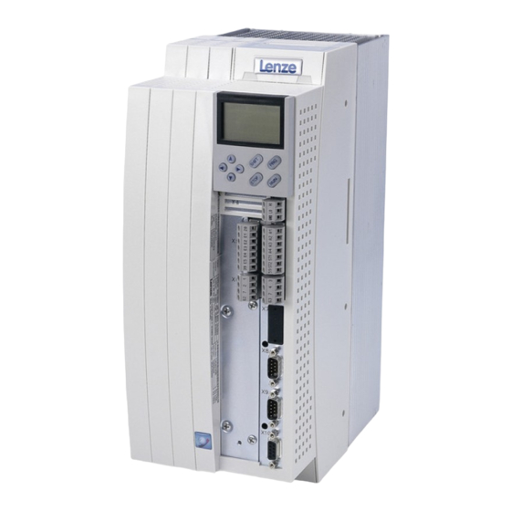
- Page 3 - Lenze Key for overview Position Description Controller Fixing bracket for standard mounting EMC shield sheet with fixing screws for shielded control cables Cover with fixing screws Shield clamp and strain relief for the motor cable Strain relief for the PE motor cable and the feed cable for the motor temperature monitoring with PTC thermi-...
-
Page 4: Table Of Contents
............General safety and application notes for Lenze controllers . -
Page 5: About This Documentation
9300 vector series installed in your machine/system. You may make further use of the information contained in this documentation without asking Lenze for permission if you do not change the contents. Document history What is new / what has changed? -
Page 6: Validity Information
- Lenze About this documentation Validity information Validity information ... 9300 vector frequency inverters as of nameplate data: ‚ ƒ Nameplate 93xx ˘ Vxxx 1x 8x Product series EVF = Frequency inverter Type no. / rated power 400V... -
Page 7: Conventions Used
- Lenze About this documentation Conventions used Conventions used This documentation uses the following conventions to distinguish between different types of information: Type of information Identification Examples/notes Spelling of numbers Decimal separator language−dependent In each case, the signs typical for the target language are used as decimal separators. -
Page 8: Notes Used
- Lenze About this documentation Notes used Notes used The following pictographs and signal words are used in this documentation to indicate dangers and important information: Safety instructions Structure of safety instructions: Danger! (characterises the type and severity of danger) -
Page 9: Safety Instructions
Lenze Automation GmbH does not accept any liability for the suitability of the procedures and circuit proposals described. Depending on their degree of protection, some parts of the Lenze controllers ƒ (frequency inverters, servo inverters, DC speed controllers) and their accessory components can be live, moving and rotating during operation. - Page 10 - Lenze Safety instructions General safety and application notes for Lenze controllers Application as directed Controllers are components which are designed for installation in electrical systems or machines. They are not to be used as domestic appliances, but only for industrial purposes according to EN 61000−3−2.
- Page 11 Reduce housing openings and cutouts to a minimum. Lenze controllers can cause a DC current in the PE conductor. If a residual current device (RCD) is used for protection in the event of direct or indirect contact, a residual current device (RCD) of type B must be used on the supply side of the controller in case of a three−phase controller supply.
-
Page 12: Thermal Motor Monitoring
- Lenze Safety instructions Thermal motor monitoring Description Thermal motor monitoring 2.2.1 Description Note! From software version 8.1 onwards, the 9300 vector controllers are provided with an I xt function for sensorless thermal monitoring of the connected motor. xt monitoring is based on a mathematical model which calculates a ƒ... -
Page 13: Parameter Setting
- Lenze Safety instructions Thermal motor monitoring Parameter setting 2.2.2 Parameter setting Parameter setting Code Meaning Value range Lenze setting C0066 Display of the I xt utilisation of the motor 0 ... 250 % − C0120 Threshold: Triggering of an "OC6" error 0 ... -
Page 14: Residual Hazards
- Lenze Safety instructions Residual hazards Residual hazards Protection of persons Before working on the controller, check that no voltage is applied to the power ƒ terminals: – Because the power terminals V, W, +U and −U remain live for at least 3 minutes after disconnecting from mains. - Page 15 - Lenze Safety instructions Residual hazards Protection of the machine/system Drives can reach dangerous overspeeds (e. g. setting of high output frequencies in ƒ connection with motors and machines not suitable for this purpose): – The drive controllers do not provide protection against such operating conditions.
-
Page 16: Safety Instructions For The Installation According To Ul Or Ur
- Lenze Safety instructions Safety instructions for the installation according to UL or UR Safety instructions for the installation according to U or U Warnings! Motor Overload Protection ƒ – For information on the protection level of the internal overload protection for a motor load, see the corresponding manuals or software helps. -
Page 17: Parameter Setting
- Lenze Parameter setting Parameter setting with the XT EMZ9371BC keypad General data and operating conditions Parameter setting Parameter setting with the XT EMZ9371BC keypad Description The keypad is available as an accessory. A full description of the keypad can be obtained from the Instructions included in the keypad delivery. -
Page 18: Installation And Commissioning
- Lenze Parameter setting Parameter setting with the XT EMZ9371BC keypad Installation and commissioning 3.1.2 Installation and commissioning SHPRG Menu 0050 Code Para 50.00_Hz M C T R L - N O U T EMZ9371BC ‚ E82ZBBXC SHPRG... -
Page 19: Display Elements And Function Keys
The set current limit is exceeded in motor or generator mode Speed controller 1 in the limitation Drive is torque−controlled (Only active for operation with standard devices of the 9300 series) Active fault 1 Acceptance of the parameters Display Meaning... - Page 20 - Lenze Parameter setting Parameter setting with the XT EMZ9371BC keypad Display elements and function keys 4 Number Active level Meaning Explanation Menu level Menu number Display is only active for operation with standard devices of the 8200 vector or 8200...
-
Page 21: Changing And Saving Parameters
Display of C0003 "PAR SAVE" 13. Set parameters for another parameter Restart the "loop" with step 1. or 3. The function of the S key can be programmed: C0469 = 1: Controller inhibit C0469 = 2: Quick stop (Lenze setting) EDKVF93−03 EN 2.0... -
Page 22: Loading A Parameter Set
- Lenze Parameter setting Parameter setting with the XT EMZ9371BC keypad Loading a parameter set 3.1.5 Loading a parameter set The keypad serves to load a saved parameter set into the main memory when the controller is inhibited. After the controller is enabled, it operates with the new parameters. -
Page 23: Transferring Parameters To Other Standard Devices
- Lenze Parameter setting Parameter setting with the XT EMZ9371BC keypad Transferring parameters to other standard devices 3.1.6 Transferring parameters to other standard devices Parameter settings can be easily copied from one standard device to another by using the keypad. - Page 24 - Lenze Parameter setting Parameter setting with the XT EMZ9371BC keypad Transferring parameters to other standard devices Copying parameter sets fom keypad into the standard device Step Action sequence Connect the keypad to standard device 2 Inhibit controller Terminal X5/28 = LOW The "IMP"...
-
Page 25: Activating Password Protection
- Lenze Parameter setting Parameter setting with the XT EMZ9371BC keypad Activating password protection 3.1.7 Activating password protection Note! If the password protection is activated (C0094 = 1 ... 9999), you only have ƒ free access to the user menu. -
Page 26: Diagnostics
- Lenze Parameter setting Parameter setting with the XT EMZ9371BC keypad Diagnostics 3.1.8 Diagnostics In the "Diagnostic" menu the two submenus "Actual info" and "History" contain all codes monitoring the drive ƒ fault/error diagnosis ƒ In the operating level, more status messages are displayed. If several status messages are active, the message with the highest priority is displayed. -
Page 27: Menu Structure
- Lenze Parameter setting Parameter setting with the XT EMZ9371BC keypad Menu structure 3.1.9 Menu structure For simple, user−friendly operation, the codes are clearly arranged in function−related menus: Main menu Submenus Description Display Display User−Menu Codes defined in C0517... - Page 28 - Lenze Parameter setting Parameter setting with the XT EMZ9371BC keypad Menu structure Main menu Submenus Description Description Display Display LECOM/AIF Configuration of operation with communication modules LECOM A/B Serial interface AIF interface Process data Status word Display of status words...
-
Page 29: Troubleshooting And Fault Elimination
- Lenze Troubleshooting and fault elimination Display of operating data, diagnostics Display of operating data Troubleshooting and fault elimination Display of operating data, diagnostics 4.1.1 Display of operating data Description Important operating parameters are measured by the controller. They can be displayed with the keypad or PC. - Page 30 - Lenze Troubleshooting and fault elimination Display of operating data, diagnostics Display of operating data Code Possible settings IMPORTANT Name Lenze Selection C0064 Utilization {1 %} 150 Device utilisation I×t Read only Device utilisation during the last 180 s of operating time C0064 >...
-
Page 31: Diagnostics
- Lenze Troubleshooting and fault elimination Display of operating data, diagnostics Diagnostics 4.1.2 Diagnostics Description Display codes for diagnostics Codes for parameter setting Code Possible settings IMPORTANT Name Lenze Selection C0093 DRIVE IDENT Controller identification Read only invalid Damaged power section... -
Page 32: Troubleshooting
- Lenze Troubleshooting and fault elimination Troubleshooting Status display via LEDs at the controller Troubleshooting Detecting breakdowns A breakdown can be detected quickly via the LEDs at the controller or via the status information at the keypad. Analysing errors Analyse the error using the history buffer. -
Page 33: Fault Analysis With The History Buffer
- Lenze Troubleshooting and fault elimination Troubleshooting Fault analysis with the history buffer 4.2.2 Fault analysis with the history buffer Retracing faults Faults can be retraced via the history buffer. Fault messages are stored in the 8 memory locations in the order of their appearance. -
Page 34: Drive Behaviour In The Event Of Faults
- Lenze Troubleshooting and fault elimination Drive behaviour in the event of faults Fault analysis with the history buffer Drive behaviour in the event of faults The controller responds differently to the three possible fault types TRIP, message, or... -
Page 35: Fault Elimination
– The motor rotates faster than the speed setpoint by the value set in C0074 (influence of the speed controller, Lenze setting 10 % of n ). After the controller is enabled, it does not stop at zero speed setpoint or quick stop (QSP). -
Page 36: Controller In Clamp Operation
- Lenze Troubleshooting and fault elimination Fault elimination Controller in clamp operation 4.4.2 Controller in clamp operation The clamp operation is a permissible operating mode. But since, however, pulse inhibit is set again and again, the controller cannot provide the optimum power. -
Page 37: Behaviour In Case Of Overvoltage In The Dc Bus (Ou Message)
- Lenze Troubleshooting and fault elimination Fault elimination Behaviour in case of overvoltage in the DC bus (OU message) 4.4.3 Behaviour in case of overvoltage in the DC bus (OU message) Description If the DC−bus voltage (U ) exceeds the switch−off threshold OU, the pulse inhibit is set. At the same time, an internal timing element starts for a delay time (C0912). - Page 38 OU is lower than the delay time set in C0912. The pulse inhibit is deactivated after the delay time in C0912 has elapsed. The delay time in [ms] is set under C0912. The Lenze setting can be changed by the ƒ...
-
Page 39: System Error Messages
- Lenze Troubleshooting and fault elimination System error messages General error messages System error messages 4.5.1 General error messages Note! If the system error is retrieved via the system bus (CAN), the error messages are displayed as numbers (see column "Error message ˘ No." of the below table). - Page 40 - Lenze Troubleshooting and fault elimination System error messages General error messages Fault message Description Description Cause Cause Remedy Remedy Display 0016 xt overload Frequent and too long Check drive dimensioning. acceleration processes with motor overcurrent. Permanent motor overload with I >I...
- Page 41 Checksum error in parameter Fault when loading a Set the required parameters set 1 parameter set. and store them under C0003 = CAUTION: The Lenze setting is Interruption while loaded automatically! transmitting the parameter set As to PLC devices, check the via keypad.
- Page 42 Fault while loading a Set the required parameters set 2 parameter set. and save them with C0003 = 2. PLEASE NOTE: The Lenze setting is Interruption during the loaded automatically! transfer of the parameter set via keypad. The parameters saved do not...
-
Page 43: Resetting System Error Messages
- Lenze Troubleshooting and fault elimination System error messages Resetting system error messages Fault message Description Description Cause Cause Remedy Remedy Display 0107 Internal fault (power stage) During initialisation of the Contact Lenze. controller, an incorrect power stage was detected. - Page 44 - Lenze © 03/2010 Lenze Automation GmbH Service Lenze Service GmbH Grünstraße 36 Breslauer Straße 3 D−40667 Meerbusch D−32699 Extertal Germany Germany +49 (0)21 32 / 99 04−0 00 80 00 / 24 4 68 77 (24 h helpline) Ê...
Need help?
Do you have a question about the 9300 Series and is the answer not in the manual?
Questions and answers