Table of Contents
Advertisement
Advertisement
Table of Contents
Troubleshooting

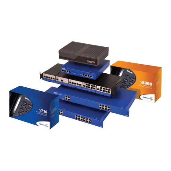
Summary of Contents for Splicecom S8000/718
- Page 1 Installation & Maintenance Manual Version 4 June 2015...
- Page 2 Installation and Maintenance Manual Document No. 001 Version No. v4/0615/10 © Copyright SpliceCom Ltd SpliceCom Ltd The Hall Business Centre, Berry Lane Chorleywood, Herts WD3 5EX Tel: 01923 287700 Website: www.splicecom.com...
-
Page 3: Table Of Contents
Installation and Maintenance Manual Contents Introduction ................................. 1 Installing a System............................... 2 Installing a S8000/S716 Call Server ......................... 2 Installing a 5100/5108 Call Server ........................3 System Configuration ............................7 Manager ................................7 Configuring System Details ..........................9 Configuring a Call Server ..........................10 System Time .............................. - Page 4 Installation and Maintenance Manual Setting up PPP ............................. 268 Setting up Bandwidth on Demand (BOD) ....................269 Maintenance & Troubleshooting ........................270 Manager Assist ............................270 System Access ............................. 272 Importing and Exporting the Configuration ....................273 Reset Switch ..............................281 Powering down a Call Server ........................
-
Page 5: Introduction
Installation and Maintenance Manual Introduction The purpose of this manual is to give a step by step guide on how to install, configure, maintain and troubleshoot a maximiser system. This manual should be used in conjunction with the maximiser Technical Reference manual which provides a feature guide of each element of a system together with an understanding of the architecture used and in-depth technical data. -
Page 6: Installing A System
Installing a System This section of the manual describes how to set up a S8000/718 and 5100/5108 Call Server where one of these will be the first unit to be installed on the customer site. Subsequent modules should then be connected to this Call Server as described in the Connecting a Module from page 29. -
Page 7: Installing A 5100/5108 Call Server
When requested for the password, enter the password for the root user on the Linux PC (if splicecom is the only user on this PC then this will be the password to use). Once the “Installation Complete” message appears and the prompt returns enter... - Page 8 Installation and Maintenance Manual will be enabled. All this configuration can be re-configured afterwards however you may wish to save yourself time by determining which of these scenarios you require before you boot up the Call Server. (Please refer to the Setting DHCP section from page 12 for further details.) When a standalone 5100/5108 Call Server is powered up it will become a Primary Call Server.
- Page 9 Installation and Maintenance Manual Please note that the front view diagram is incorrect, the first LED is the LINK LED and the second is the DISK drive LED. 4100 Call Server – Front and Rear view 4140 Remote Call Server – Front and Rear view Installing a System Installation and Maintenance Manual v4/0615/10...
- Page 10 4100 and 4140 Call Servers the NET LED will flash to indicate a system check.) The SpliceCom LED will become solid when the unit is ready. Once the 5100/5108 Call Server has been powered up the following should be noted: If the Call Server’s DHCP Server functionality has been enabled the Call Server will give out an...
-
Page 11: System Configuration
Installation and Maintenance Manual System Configuration Manager The configuration of the maximiser system is controlled and stored on the LDAP database within the Call Server. Manager is the application that is used to view and configure this database. Changes to the configuration made via Manager or by a User via their handset are stored in the RAM and copied regularly to the hard disk to be stored permanently. - Page 12 Installation and Maintenance Manual The following options will assist you to navigate and configure the database: Navigate within a list of entries Display the first page of entries Display the previous page of entries Display the next page of entries When a list of entries is displayed the Search box will be available at the top of the navigation pane.
-
Page 13: Configuring System Details
Installation and Maintenance Manual Configure an entry To open, view and edit an entry click on the blue link To save the changes and return to the previous screen To save the changes and remain in the current entry. To return to the previous screen. If changes have been made these will not be saved. To delete the entry currently displayed. -
Page 14: Configuring A Call Server
Call information to be used by third party call logging applications can be obtained from the system via Telnet to port 4001. Please refer to the Call Logging Format document available via the SpliceCom website>Reseller Area>Technical Resource>Manuals>SpliceCom APIs>Call Logging Output vx.x.x for details on the description of each field. - Page 15 Installation and Maintenance Manual The Flash LED button will instruct the Call Server’s SpliceCom LED to flash 20 times. This feature is useful when multiple Call Servers are being used on a system and will identify the physical Call Server from its configuration form.
- Page 16 Installation and Maintenance Manual A list of each module’s IP address can be viewed in Manager by opening Manager Assist and selecting System Utilities and then IP Addresses. Setting DHCP on a 5100/5018 Call Server During power up a 5100/5018 Call Server will search for a DHCP Server, if not found, its internal DHCP server functionality will be enabled and will give out an address range of 192.168.0.1 to 192.168.0.250.
-
Page 17: System Time
If the DHCP Server Mode is set to Client and the Call Server is unable find a DHCP server on reboot the SpliceCom LED will turn on for 5 seconds then off for 5 seconds continually until a DHCP server is found. -
Page 18: Setting Up Administrative Access
Installation and Maintenance Manual Please note: The system will take into account British Summer Time. If multiply Call Servers are being used on one system the above time will be the time used by the Call Server whose Manager is being viewed. Each Call Server can have a different date and time. This information will be sent and updated on all handsets registered to the specific Call Server. - Page 19 Installation and Maintenance Manual Additional Administrators Additional administrators can also be created to enable staff to log on to Manager but have limited access to the configuration. A new administrator can be created as follows. Creating a new Administrator via the wizard In Manager, open Manager Assist and select System Wizards Select System Administrators Enter a Name, Description and Password for the new administrator.
- Page 20 Installation and Maintenance Manual Select the Next Page button. From the Add Default Rights list box select either: Yes – all rights will be given to each page listed below, however full access will be dependent on whether Yes or No was selected within the previous page. No –...
- Page 21 Installation and Maintenance Manual Creating a new Administrator manually In Manager, select Administrators The Administrator List will be displayed Select the Add button Enter the name required for the new Administrator Enter a description if required to further identify this Administrator Enter the password to be used by this Administrator.
- Page 22 Installation and Maintenance Manual If the Companies feature is being used on this system select the company that this administrator can have access to (otherwise the administrator will have access to all Users, Departments etc). For further information on the Companies feature please refer to page 177. If you wish the administrator to be shown a specific page of the database on opening Manager from the Default Page list box select the page required, eg Contacts.
- Page 23 Installation and Maintenance Manual Creating an Administrator for a Company If the maximiser system is using the Companies feature you may wish an Administrator only to have access to the entries relating to a specific Company. In this case within the required Administrator’s configuration form select the Company field and select the required Company from the Select Company list.
-
Page 24: Licencing
Installation and Maintenance Manual Within the PCS 60 application enter the Administrator Name and Password in the PCS 60 Preferences dialogue box. For further information on please refer to the PCS 60 Operator Console Mode section on page 77 and to the PCS 60 User Manual. - Page 25 Installation and Maintenance Manual note: a list of which Users and Departments have been assigned MessageBox licences can be viewed in Manager Assist by selecting System Checks and then System Licences then either User Licence Status or Department Licence Status at the top right hand side.) A VoicemailPort licence will enable an additional port/simultaneous voicemail connection on a system.
- Page 26 Installation and Maintenance Manual Licences summary In summary, the licences available on a maximiser system are as follows: Licence Name Description 5108Plus Increases the number of Users supported by a 5108 Call Server to 12. The maximum number of analogue users stays at four however the IP phone users can increase to 8, or in an IP only environment all 12 users could be IP phone users.
- Page 27 Installation and Maintenance Manual Licence Name Description Trunk Enables the use of ISDN, SIP, H.323 or DPNSS channels. One licence per channel up to a maximum of 120 on a S8100, 68 channels on a 5100 and S8004-50, 34 on an NSG, 8 on a 5108 and I208, and 30 on a I230.. VisionReport For use with Vision.
- Page 28 Installation and Maintenance Manual Module Licence Action 5108 Call Server POTS Activating Ports 1-4 IPUser 4 Users automatically created Trunk Activating BRI1 VoicemailPort Enabling 2 simultaneous voicemail connections MessageBox Supplied and installation required 5500 Network Service Gateway POTS Activating Ports 1-4 IPUser 4 Users automatically created Trunk...
- Page 29 Installation and Maintenance Manual The licences installed will be displayed in the Licences List, similar to the following diagram: If a licence has not been entered correctly and not authenticated the Invalid message will be displayed with the licence. An error message will also appear in the Warnings screen within Manager which can be accessed as follows: Open Manager Assist and select System Utilities Under the Diagnostics list select Warnings...
- Page 30 Installation and Maintenance Manual Download Licences Licences can be downloaded directly from SpliceCom by using the Download Licences option. The System Name and Supplier must be previously entered. You will require an internet connection and your Forums registered email address and password. Please refer to Support for further assistance.
- Page 31 It also forms part of Splicecom’s Software Protection programme in accordance with the EU Directives on software sales. The Heartbeat process utilises SSL, port 443, to establish a secure connection to the SpliceCom Heartbeat Server. Therefore ensure that this port is open within any Firewall/router configuration. In the case where Proxy Servers are being utilised on the customer network, the Proxy Server will need to be configured to listen for requests on port 443 as well as port 80.
- Page 32 SoftPBX, the Technical Support team will telephone the appropriate Reseller’s technical contact to alert them to the possible problem. The issue will be tracked by SpliceCom and if not resolved before the SoftPBX has only 10 days of operational life remaining, the matter will be escalated to the Reseller’s Principal.
-
Page 33: Connecting A Module
Installation and Maintenance Manual The additional Users, up to 12, can now be created assuming the required number of IPUser licences have been installed. Connecting a Module Connecting an Intelligent Gateway Module PSU (PoE4) The PoE4 provides four Power over Ethernet ports, primarily for use with the Intelligent Gateway Modules. Please refer to the Technical Reference manual for technical data relating to this module. - Page 34 Installation and Maintenance Manual Initial Considerations Power is supplied by Power over Ethernet (PoE) which can be provided via an Intelligent Gateway Module PSU (PoE4), third party PoE switch or via a PoE LAN port available on a 5100 and 5018 Call Server or 5300 Phone Module.
- Page 35 P308. In turn the I208/I230 will store in RAM configuration information relevant to its functionality. The Flash LED button will instruct the I208/I230’s SpliceCom LED to flash. This feature is useful when multiple I208/I230s are being used on a system and will identify the physical I208/I230 from its corresponding configuration form.
- Page 36 Installation and Maintenance Manual Changing the Password When accessing the configuration web pages for an I208/I230 as described below, the module’s password is entered on connection. When accessing the I208/I230 via a ssh terminal window the login name is diag and then the password for the module is entered. By default this password is set to 7388. However this password can be changed as follows: In Manager select Modules Select the I208/I230 required...
- Page 37 Installation and Maintenance Manual Network Configuration Type – this section can be used to give the I208/I230 a static IP address (or return the module to using DHCP). Select Static and then enter the IP address, subnet mask and default gateway address required. VPN Configuration –...
- Page 38 Having obtained an IP address the module broadcasts to find a Call Server to provide its configuration and become active. The SpliceCom LED will become solid when the unit is ready. In Manager select Unassigned Modules The Trunk Module will be displayed together with its MAC address, eg SpliceGateway5230 00-07-d9-00-b8-67.
- Page 39 Trunk Module will store in RAM configuration information relevant to its functionality. The Flash LED button will instruct the Trunk Module’s SpliceCom LED to flash. This feature is useful when multiple Trunk Modules are being used on a system and will identify the physical Trunk Module from its corresponding configuration form.
- Page 40 Installation and Maintenance Manual Setting the IP Address of the Trunk Module When connecting a Trunk Module to the system for the first time a DHCP server is required to give the Trunk Module an IP address. This address can be viewed within the Trunk Module’s configuration form as described above.
- Page 41 Having obtained an IP address the module broadcasts to find a Call Server to provide its configuration and become active. The SpliceCom LED will become solid when the unit is ready. In Manager, select Unassigned Modules The VCM will be displayed together with its MAC address Select this link The Module Status field will display “Available”...
- Page 42 The Flash LED button will instruct the VCM’s SpliceCom LED to flash. This feature is useful when multiple VCMs are being used on a system and will identify the physical VCM from its corresponding configuration form.
- Page 43 Installation and Maintenance Manual If calls are to be made to a Call Server that does not contain a Voice Compression Card or does not have a Voice Compression Module connected it is recommended that the this Intramodule Trunk is also created.
- Page 44 Installation and Maintenance Manual Extension numbers used will commence with the next available number, therefore if, for example, the existing extension number range on a system is 2001-2016, and a P308 is installed the Users automatically created will be given an extension number within the range of 2017-2024. (This default configuration can be amended for each User after installation if required, please refer to the Configuring a User section from page 95 for further details.) To change the extension number range automatically used when a Phone Module/P308/IP Phone...
- Page 45 Installation and Maintenance Manual Powering up the P308 Connect the P308 to the system via the LINK port on the front of the module. This can be either via the network or directly to a LAN port on a 5100/5018 Call Server or Phone Module. The module will request an IP address from a DHCP server.
- Page 46 User configuration, to the Call Server. The Flash LED button will instruct the P308’s SpliceCom LED to flash. This feature is useful when multiple P308s are being used on a system and will identify the physical P308 from its corresponding configuration form.
- Page 47 Installation and Maintenance Manual Setting the IP address and Network configuration The network configuration of the P308 can be set by accessing the configuration web page as follows: 1. Within any browser enter the IP address of the P308 , eg 192.168.0.38 2.
- Page 48 Installation and Maintenance Manual Alt Gatekeeper – the IP address of the S8000/S716/5100/5108/NSG that you want the module to register to if the first Gatekeeper fails) TFTP, NFS, and DNS settings – these are typically the S8000/S716/5100/5108/NSG that the P308 is connected to.
- Page 49 Having obtained an IP address the module broadcasts to find a Call Server to provide its configuration and become active. The SpliceCom LED will become solid when the unit is ready. If the Auto Add Phones feature is turned on the Phone Module will automatically register with the...
- Page 50 Phone Module will pass back configuration changes, eg User configuration, to the Call Server. The Flash LED button will instruct the Phone Module’s SpliceCom LED to flash. This feature is useful when multiple Phone Modules are being used on a system and will identify the physical Phone Module from its corresponding configuration form.
- Page 51 Installation and Maintenance Manual Each port on the Phone Module can now be configured independently, see page 89 for further details. Changing the Password When accessing a Phone Module via Telnet, when upgrading for example, the module’s password is entered on connection. By default this is set to 7388. However this password can be changed as follows: In Manager select Modules Select the Phone Module required Select the Phone Module page...
-
Page 52: Connecting An Analogue Phone
Installation and Maintenance Manual Enter setnet then press Enter The current configuration will be displayed. You will be asked if you wish to change any of this configuration. Enter y then press Enter You will be asked how the IP address will be assigned. Delete the d and enter s then press Enter Follow the onscreen prompts entering the IP address you wish to give the Phone Module, eg 192.168.0.50, the netmask you wish to use, eg 255.255.255.0 , the IP address of the Gateway... - Page 53 Installation and Maintenance Manual Each port is provided with two LEDs to display the following activity on the port: Left hand LED = displays when phone ringing Right hand LED = displays when phone in use When a 5100 or 4140 Call Server or Phone Module is rebooted each analogue handset will ring once to confirm communication with the system and will display the number of new voicemail messages waiting for the User assigned to that phone (if voicemail enabled).
- Page 54 To increase the volume output for the analogue ports on a Call Server a file called pots_level must be created within the /SpliceCom directory as follows: Telnet on to the Call Server as described in the Root Access to a Call Server section from page 272...
-
Page 55: Connecting A Pcs Ip Phone
Installation and Maintenance Manual Default Dial Plan entries The PCS 520 is supplied with 10 pre-programmed buttons which dial specific dial plan entries. Therefore the User assigned to the PCS 520 must be configured with a Dial Plan containing these default dial plan entries. - Page 56 Installation and Maintenance Manual PCS 58x/57x/56x/55x/542 – via one of the PoE LAN ports on a Call Server or Phone Module, or via a Single Terminal Ethernet Power Supply (STEPS) PCS 410/100 - via one of the PoE LAN ports on a Call server or Phone Module, or via a Single Terminal Ethernet Power Supply (STEPS) PCS 400 - via one of the PoE LAN ports on a Call server or Phone Module, or via a Single Terminal Ethernet Power Supply (STEPS).
- Page 57 Please refer to the Using Auto Add Phones section from page 13 for further details. The Home page presenting the SpliceCom logo, the User’s name, extension number, system name and the date and time will be displayed once the installation is complete.
- Page 58 Installation and Maintenance Manual Select Update or Apply to save the changes. Please note the WebSetnet feature in Manager Assist will only operate if the handset(s) is using the default login password. Viewing the IP address of the PCS 58x/57x/56x/55x To determine the IP address of a PCS 55x/57x/56x select the Favourites button , then Settings and then Phone Information (alternatively press the key at the bottom right hand side and then select Phone...
- Page 59 Installation and Maintenance Manual In the Phones Base Address: field enter the IP address of the handset (if you wish to configure more than one enter the first IP address of the range and then the last part of the IP address of the last IP address in the range, eg 192.168.0.53-58.
- Page 60 Installation and Maintenance Manual Via Setnet Within the Command prompt enter eg telnet 192.168.0.24 telnet <ip address of PCS 58x/57x/56x/55x/542> You will be prompted for a Username, enter diag You will be prompted for the password for this phone. By default this is 7388. (Please refer to the Setting the Password section from page 53 for further details.) Wait for a # to appear to confirm a connection has been made to the PCS Enter setnet...
- Page 61 Installation and Maintenance Manual If there are more than one remote IP Phone connected to the system one of these phones can be configured to collect the BLF data from all the remote phones and send this to the system. This can be achieved by entering –relay after the IP address, eg –gk 192.168.0.1 –relay.
- Page 62 (you can change to the logos directory and check that the file has been moved to here.) Enter cd /SpliceCom Enter /SpliceCom/pcs5xx_customise pcs5xx pcs5x1-256M.site (for the PCS 572/562 phones) /SpliceCom/pcs5xx_customise pcs5xx pcs5xx-256M.site (for the PCS 570/560 phones) You will receive a message indicating that the customisation file is ready for the upgrade.
- Page 63 Installation and Maintenance Manual Operator Console Mode When a PCS 58x/57x/56x is being used by a receptionist or switchboard operator the Operator Console Mode can be enabled to provide the operator with additional data to assist with the efficient handling of calls.
- Page 64 The User’s Initial Phone field displays the name of the PCS that is assigned to this User. The above procedures also apply to non-SpliceCom IP Phones. A list of recommended IP Phones is available from our Marketing department.
- Page 65 Installation and Maintenance Manual A list of the IP Addresses for each PCS 410/400/100 can be viewed in Manager Assist by selecting System Utilities and then IP Addresses. Setting the IP Address When connecting a PCS 410/400/100 to the system for the first time a DHCP server is required to give the PCS an IP address.
-
Page 66: Installing User Software
Installation and Maintenance Manual Connect to the Call Server remotely If the PCS 410/400/100 is to be installed at a remote location, eg via a VPN connection, the phone should be configured with the IP address of the Call Server it is to connect to as follows. Follow steps 1-7 as described above to telnet on to the phone and access Setnet. - Page 67 13 for further details.) Running Navigate: Run the Navigate.exe file either from the installation folder, eg C:\Program Files\SpliceCom\Navigate, or via the Windows Start menu or via the short cut created during installation. The Navigate application will open.
- Page 68 Installation and Maintenance Manual In the IP Address field enter the IP address of the Call Server you wish this software to register to. Select OK when ready. Click on the Softphone button and you will receive a message indicating that a restart is required. Select Yes to continue.
- Page 69 Installation and Maintenance Manual Select the Licences tab. Select the Navigate Softphone Licence box. Select Update or Apply when ready. (This setting will not be saved if a Navigate SoftPhone licence is not available.) Return to Navigate. Click on the Softphone button and restart Navigate. Once open Navigate will display “Navigate (Softphone) - <user name>”...
- Page 70 Run the Navigate as a partner Run the Navigate.exe file either from the installation folder, eg C:\Program Files\SpliceCom\Navigate, or via the Windows Start menu or via the short cut created during installation. The Navigate application will open. The “Searching for Server” message will be displayed within the Notification Area of the PC.
- Page 71 At the Welcome screen select Next to continue the installation By default the software will be loaded into C:\Program Files\SpliceCom\PCS60. Change this location if required. Where relevant you will also have the option to load the software for all Users of the PC or just for the currently logged in User.
- Page 72 20.) Running the PCS 60: Run the PCS60.exe file either from the Installation folder, eg C:\Program Files\SpliceCom\PCS60, or create a short cut to this file in the required location and double click on the short cut. The PCS 60 application will open.
- Page 73 In the Target field add -gk <ip address of Call Server>, eg –gk 192.168.0.1 so that the Target path reads as per the following example: “C:\Program Files\SpliceCom\PCS60\PCS60.exe” –gk 192.168.0.1 c Select OK. d Double click on the short cut to run the PCS 60.
- Page 74 Installation and Maintenance Manual Please note that entries made in the short cut Properties will override the entries made in the Preferences dialog box. Remote BLF If the call server is to collect BLF information from this remote PCS 60 IP Phone the Remote BLF option should be enabled as follows.
- Page 75 Select Update or Apply when ready. Run the PCS 60 as a partner Run the PCS60.exe file either from the Installation folder, eg C:\Program Files\SpliceCom\PCS60, or create a short cut to this file in the required location and double click on the short cut. (Please note that if you do not wish the PCS 60 to be loaded initially as an IP soft phone disconnect the PC from the network or turn off Auto Add Phones.)
- Page 76 -pots <ip address of PCS 58x/57x/56x/55x/410/400/100>:<5001>,<partner login code> so that the Target path reads as per the following example: “C:\Program Files\SpliceCom\PCS60.exe” -pots 192.168.0.249:5010,1234 Select OK when ready Double click on the short cut to run the PCS 60 application...
- Page 77 Installation and Maintenance Manual Run (double click) the set up file called, for example, PCS60_MAC.3.2.67.pkg At the Welcome screen select Continue to start the installation At the Select a Destination screen select the Volume where you want the software loaded By default the software will be loaded into the Applications folder.
- Page 78 Installation and Maintenance Manual The User’s Initial Phone field displays the PCS 60 that the User is assigned to, identified by the hardware address of the PC. Connect to the Call Server remotely If the PCS 60 is to be run remotely over, a different subnet, a VPN, for example, the application must be configured with the IP address of the gatekeeper, in other words the Call Server, before the registration process can take place.
- Page 79 Installation and Maintenance Manual It is recommended that no more than 5-6 remote IP phones should be configured to use this facility in order to keep the overhead on the Call Server to a minimum. PCS 60 on an Apple Mac PC as a partner to a User’s handset The PCS 60 can be run as partner to any PCS 58x, 57x, 56x, 55x or analogue handset being used on the maximiser system giving the user the additional functionality provided by the PCS 60.
- Page 80 Installation and Maintenance Manual Select Update or Apply when ready. Run the PCS 60 as a partner Run the PCS60 software either from Applications or create an Alias to this file in the required location and double click on the Alias. (Please note that if you do not wish the PCS 60 to be loaded initially as an IP soft phone disconnect the PC from the network or turn off Auto Add Phones.) The PCS 60 application will open.
- Page 81 Installation and Maintenance Manual Run more than one version of PCS 60 on the same Apple Mac PC When a member of staff is responsible for monitoring or using multiple handsets for example, multiple PCS 60 windows can be run on the same PC by making a copy of the software and entering the required settings in the Preferences form of each copy of the PCS 60 software.
- Page 82 An IPUser licence must be previously installed and be available. (For further details please refer to page 20.) Running the PCS 50: Run the PCS.exe file either from the Installation folder, eg C:\Program Files\SpliceCom\PCS50, or via the short cut created during the installation The PCS 50 application will open.
- Page 83 Please note that the PCS 50 software is stored as PCS.exe in the Installation folder, eg C:\Program Files\SpliceCom\PCS50, or can be access via the short cut created during the installation Installing the PCS 50 software on a Mac OS X The set up file will be supplied in a compressed folder called, for example, PCS50.2.2.667.pkg.zip.
-
Page 84: Installing The Ssl Gateway Application
Installing the SSL Gateway Application The Securet Socket Layer (SSL) Gateway application can be used to connect remote PCS 5x2/3 IP phones and Splicecom soft phone applications to a maximiser system. Before starting: Ensure the system Call Servers are running the required version of software as specified in the Forums. - Page 85 DHCP, IP routing, DNS, NFS Server and NTP services are all configured within Linux The Linux PC must have a User called “splicecom”. It is recommended that Auto Login is turned off for this User account. You will need to know the root password to enter and execute Terminal commands during installation and configuration.
- Page 86 SSL config files - the default is port 5000. Log Files - The SSL Gateway Application will store logs in the /SpliceCom/logs directory on both Linux and MAC OS X platforms. The log will only be generated once a connection is made to the SSL Gateway app.
-
Page 87: Connecting Multiple Call Servers
Installation and Maintenance Manual Select Done Pressing Settings at the top left hand side of the screen to return to the previous screen Slide the Enable button to On The iPCS will now try to connect to the Call Server like a normal PCS IP phone If Auto Add Phones turned off, go to Unassigned Phones in Manager Select the iPCS phone and make it a Member and User account will be created for the phone Open this User’s configuration form... - Page 88 Installation and Maintenance Manual e Connect the Call Server to the Primary Call Server either via the network or directly to a LAN port on the Primary Call Server. f Power up the Call Server g Open Manager on the Secondary Call Server, eg http://192.16.0.252/manager h Within Manager Assist, select System Utilities Under the Commands list select Ask Master Within the Enter IP Address field enter the IP Address of the Primary Call Server, eg 192.168.0.1...
- Page 89 Installation and Maintenance Manual e Select the default WANLink. f Select the IPRoutes page g Remove all the existing routes and add an entry to route back to the Primary Call Server, eg IP Address = 194.168.0.0 IP Mask = 255.255.255.0 Metric = 1 h Power down the Call Server, as described in the Powering down a Call Server section from page 282.
- Page 90 LAN port on the 5100 Call Server, if relevant. Enter poweroff to reboot the NSG When the NSG is ready (the SpliceCom LED is solid) open Manager on the Primary Call Server From the navigation pane, select Unassigned Modules The NSG will be listed. Select this link to open the NSG’s configuration form.
- Page 91 Installation and Maintenance Manual The Call Server field within the Phone or Trunk Module’s configuration form will display the name of the Call Server that the module it is connected to, ie the name of the Secondary Call Server. When connecting a Phone Module to a Secondary Call Server the additional Users created are all listed under the Users list and have taken the next available extension numbers.
- Page 92 Installation and Maintenance Manual Primary Call Server Secondary Call Server Each Secondary Call Server will be responsible for passing on relevant configuration information to Phone and Trunk Modules, IP Phones etc that are directly connected to this Call Server. Any configuration information received from these Phone Modules, Trunk Modules or IP Phones etc will be passed back to the Primary Call Server by the Secondary Call Server for storage in the master database.
-
Page 93: Configuring System Functionality
Installation and Maintenance Manual Configuring system functionality Configuring an Analogue Extension Port Physical analogue extension ports on a Phone module or Call Server can be configured as follows: In Manager select Phones Select the relevant Phone Module or Call Server Select the port you wish to configure The port is automatically assigned a name which cannot be changed. - Page 94 Installation and Maintenance Manual Caller Display Type None – Call Display information will not be sent to the extension and the extension will not ring once after the relevant Phone Module has been rebooted Default – PCS 10 (suitable for most analogue handsets) Alarm –...
-
Page 95: Configuring An Ip Phone
Installation and Maintenance Manual None – this port will be used as a standard extension with an analogue phone. Paging – this port will be used by an external paging source, for example, a tannoy or PA system. A Paging Port Adapter is required to connect the powered speakers (please refer to the maximiser Technical Reference manual for the specifications for this adapter.). - Page 96 Installation and Maintenance Manual You may wish to change the Name and/or the Description to assist with identifying the phone eg its physical location etc. This name is used by a User’s Initial Phone field to indicate the IP phone to which they are assigned.
- Page 97 Installation and Maintenance Manual Extension Anywhere For information on the Extension Anywhere and Remote Idle fields please refer to the Setting up Extension Anywhere section from page 126. Headset Working Tick this box if a headset is used in conjunction with the phone connected to this port. This feature allows the use of a headset without picking up the receiver.
-
Page 98: Working With Users
Installation and Maintenance Manual Alternatively, 1. From Manager Assist select System Wizards, and then PCS5xx Screen Saver. 2. From the Mode list select the Screen Saver Mode you wish to apply. 3. Enter the parameters required. 4. Select the Configure all now button to apply this configuration to every IP phone on the system. 4. - Page 99 Installation and Maintenance Manual Alternatively, a User account can be created via Manager Assist>Configuration Aids>Users – Add New User. If invalid characters or a duplicate name or extension number are entered a warning will be displayed until the entry is changed. The Current Home field will contain a default entry, if this is not the Call Server required select the correct one from the list.
- Page 100 Installation and Maintenance Manual Each User is assigned a Display Name which is used to identify them on the system, for example, when calls to and from this User are made the name will appear in Caller Display. It is recommended that this be changed to a unique, relevant name.
- Page 101 Installation and Maintenance Manual The Description field is a text field which can be used to further assist with identification of the User in Manager and via the Users directory accessed on the PCS 58x/57x/56x/55x/410/400/60/50, eg Personnel Director, Security, Reception etc The Telephone Number field determines the internal number for the User.
- Page 102 If the entry in this field is removed the logo displayed will return to the image specified in the site file or to the default SpliceCom image. The Display Mode field determines the information displayed on the Home screen of the User’s PCS 5xx IP phone.
- Page 103 Installation and Maintenance Manual Duplicate User Names and Extension Numbers It is essential that duplicate User Names and Extension Numbers are not used on a system. To ensure that duplicates have not been entered, within Manager Assist, select System Utilities and then Sorted. This page will highlight entries where an identical name or extension number exists.
- Page 104 Installation and Maintenance Manual Changing the extension numbers for multiple Users When the extension number for more than one User is to be changed the Users (Renumber) feature can be used as follows: In Manager, select Users (Renumber) In the New Number Base field enter the first number of the new range to be used, for example, if you wish to renumber the extensions from 6001 to 6050 enter 6001.
- Page 105 From the User list select the User required. In the Auto URL field enter the path to the web page to be displayed, eg www.splicecom.com/accounts or http://192.168.0.1/sales.php From the Auto URL Mode list box select one of the following: a NoAction – the web page specified in the Auto URL field can be viewed via the Information icon on a PCS involved in a call to or from this User b On Ring –...
- Page 106 Installation and Maintenance Manual c Out – the web page will only be displayed on the PCS making the internal call either to or from this User. The User’s PCS will also display the web page when an external call is made by the User.
- Page 107 Installation and Maintenance Manual Users can also add and edit their own personal numbers via their PCS 58x, 57x, 56x, 55x, PCS 410/400, PCS 60 or PCS 50. This facility is controlled by the Edit Mode field under the General Page. By default this is set to All which gives the User full rights to edit his Number fields.
- Page 108 Installation and Maintenance Manual g Dual Personal External - all external calls to the User’s extension number and DDI will be forwarded, and the User’s extension will ring. (Calls to the User’s Department(s) will ring on the User’s extension.) h All External - all external calls to the User’s extension number and DDI will be forwarded plus any calls to a Department to which the User is a member.
- Page 109 Installation and Maintenance Manual Turn off Follow Me In Manager select Users Select the User you wish to configure Select the Telephony page From the Follow Me list box select None The Follow Me To number can remain for future use Select Update or Apply when ready Please note: The above Follow Me features can be set by the User via their PCS 58x/57x/56x, PCS 55x, PCS 60,...
- Page 110 Installation and Maintenance Manual If the Forward on Busy number is not answered within the original User’s No Answer Time the call will be routed to the original User’s voicemail, no further forwarding occurs. If the Forward on Busy number is busy and Forward on Busy is set for that extension the call will be forwarded on.
- Page 111 Installation and Maintenance Manual If the Forward on No Answer number has Follow Me set the call will be forwarded on. If the Forward on No Answer number is also not answered within the original User’s No Answer Time the call will be routed to the original User’s voicemail, no further forwarding occurs. If the Forward on No Answer number is busy and Forward on Busy is set for that extension the call will be forwarded on.
- Page 112 Installation and Maintenance Manual A User may prefer not to hear the intermittent beep; this can be achieved by selecting the NoBeep option. If a User of Navigate, PCS 60 or PCS 50, operating as a partner to their handset, would prefer not to hear the intermittent beep in the headset this can be achieved by selecting the PhoneTools option.
- Page 113 Installation and Maintenance Manual Call Barring Users can be barred from making calls to specific numbers or for all external calls. To bar calls to all external numbers: In Manager select Users Select the User you wish to configure Select the Telephony page Tick Outgoing Call Bar Select Update or Apply when ready Please note: When this feature is set the User cannot make a call to any external number including...
- Page 114 Installation and Maintenance Manual Select the Telephony page In the Login Access Code field enter a number (max 8 digits) that will be the User’s passcode. If required, in the Login Idle Time field, enter the number of seconds this User will be idle before being automatic logged off.
- Page 115 Installation and Maintenance Manual A PCS 58x/56x/57x/55x, PCS 410/400, PCS 100, PCS 60 IP Phone and PCS 50 IP Phone. (Please refer to the relevant User Manual for details on how to log on to these handsets.) The handset will return to the assigned User:- When the User logs off via a Dial Plan entry (examples shown above) or via the handset’s log out procedure.
- Page 116 Installation and Maintenance Manual Creating a Virtual User A Virtual User is a User created on the system to facilitate PBX functionality only. This User does not require a physical extension and will not be logging on to a physical extension. For example, this facility can be used in a school where teachers will be checking and collecting their voicemail from a single phone in the staff room.
- Page 117 Installation and Maintenance Manual In the Telephone Number field enter the internal or external number required Select Update when ready The number entered will be displayed under the Exception Telephone Number list. Click on this number if an amendment is required. Repeat steps 4 and 8 to add all numbers required Select Update or Apply when ready When a call is received from a DND Exception Number the call will be presented to the extension as...
- Page 118 Installation and Maintenance Manual Select Update or Apply when ready The message will appear on a caller’s Navigate, PCS 50, 60, 100, 410/400, PCS 55x, PCS 56x/57x/58x when a call is made to this User’s extension (please refer to relevant user manual for further details.) When an Out of Office message has been selected and a caller goes to voicemail the relevant voicemail greeting will be played, please refer to the Voicemail Settings section from page 223 for further details.
- Page 119 Installation and Maintenance Manual Select Apply when ready Select Add Capability Within the Capability field enter the skill required eg French (this must match exactly the name entered in the User’s Capability field) Within the Capability Percent field enter the percentage level of skill required eg 50 Select Update when ready The Group will be automatically populated with the Users meeting this skill level.
- Page 120 The Navigate WAV files are stored by default in C:\Program Files\Splicecom\Navigate\res. The PCS 60 WAV files are stored by default in C:\Program Files\Splicecom\PCS 60\res. The PCS 50 WAV files are stored by default in C:\Program Files\PCS50\res. All the files are formatted as CCITT A-Law 8.000kHz 8bit mono.
- Page 121 Ring tunes for PCS IP Phones can be programmed locally using a .site file, please refer to the “Changing the Logo pic on a PCS 5xx” FAQ on the SpliceCom Forums for instructions on how to set up ring tunes for these phones.
- Page 122 Installation and Maintenance Manual In Manager select Users Select the User required Select the Tunes page Select Add Ring Tune Delete the entry in the Telephone Number field From the Ring Type list box select Parallel From the Ring Tune list box select the ring tune required Select Update or Apply when ready Specify a Ring Tune for System calls...
- Page 123 Installation and Maintenance Manual Please note: User Short Codes take priority over Dial Plan entries. Disable Call Pick Up Speed Dials created for internal extensions can also be used to pick up a call ringing on that extension, if however a User on that extension, such as the MD of the company, does not want his/her calls picked up the hash (#) can added to the beginning of the Telephone Number field.
- Page 124 Installation and Maintenance Manual Remove Row = this will remove the last row added, ie the bottom row. Update Existing Speed Dials – use this action to amend specific Speed Dials for specific Users. This can be used to amend the number dialled and/or the Description. Remove Exisiting Speed Dials –...
- Page 125 Installation and Maintenance Manual Favourite Groups Where Users have multiple Speed Dials displayed in their Favourites they may wish to organise these into groups to make them easier to find. For example, a User may wish to organise her speed dials by project or department such as Road Show, Directors, Accounts, or separate personal speed dials from business speed dials, and so on.
- Page 126 Installation and Maintenance Manual To determine where in the list a Speed Dial assigned to a Favourite Group will be displayed add a comma and then the order number required, eg G:2,3. Where two or more Speed Dials or Favourite Groups are given the same order number these will be displayed in alphabetical order.
- Page 127 Installation and Maintenance Manual On a PCS 100 the Favourite Group ( Exhibition) will be displayed in the Favourites screen and can be selected by pressing the Context Sensitive Key beside this entry. The Speed Dials assigned to this Group will then be displayed.
- Page 128 Installation and Maintenance Manual Using the Park facility via Dial Plan entries A call can be parked and picked up via a Dial Plan entry as per the following examples. The call must be put on hold first and then the relevant short code is entered. (Please refer to the Working with Dial Plans section for further details on creating a Dial Plan entry.) Park a call The call will be parked in the next available slot...
- Page 129 Installation and Maintenance Manual The number of the Park Slot from which a call is to be picked up is entered in the Translate To field. Therefore in this example User would enter **55 to pick up a call parked in slot 55. Changing the Park icons/buttons on a PCS IP phone By default, a User of a PCS 58x/57x/56x/55x, 410/400, 100, 60, or 50 is given access to park slots 1, 2, 3, and 4 via an icon/button (please refer to the relevant User manual for instructions on how to use these...
- Page 130 Installation and Maintenance Manual Either via Manager Assist>Configuration Aids>Speed Dials or via the User’s Speed Dial page create a new Speed Dial slot In the Telephone Number field enter following by the slot number required, eg slot8 In the Description field enter the text (alpha-numeric characters) you wish to use to identify this Park icon preceded by a colon, eg :Sales Park.
- Page 131 Installation and Maintenance Manual the User is able to receive CLI at home or on their mobile (this service is arranged through the User’s telephone company) the User will be able to differentiate between business and personal calls. No drop in speech quality will occur when using PSTN lines which may happen when using VoIP over the Internet.
- Page 132 Installation and Maintenance Manual parts of the call and the User’s office DDI number will be sent with the CLI information rather than the User’s home number. Please note: Navigate or PCS 60/50 only needs to be running when an outgoing business call is to be made.
- Page 133 Installation and Maintenance Manual Users of a PCS 58x, 57x, 56x, 55x or 542 will be able to turn Extension Anywhere on or off via Settings. (Please refer to the relevant user manual for further details.) If numbers have been entered in the Details page of their User configuration form the User will be given the option to select these numbers from a ready-made list.
-
Page 134: Working With Dial Plans
Installation and Maintenance Manual Working with Dial Plans Dial Plans determine how digits dialled on a User’s extension are handled. A Dial Plan will allow you to create speed dials, short codes to system features and set up call barring. A Dial Plan can be assigned to one or many Users. - Page 135 Installation and Maintenance Manual From the Action list box select the action to be performed by the system eg Dial. (Please refer to page 326 for a description of each Action.) In the Translate To field enter the digits to be processed by the system eg 01923716260 If you wish to specify the outgoing CLI to be sent when this Dial Plan entry is used enter the User or...
- Page 136 Installation and Maintenance Manual In the Translate CLI To field - ? (question mark) = withhold the outgoing number Assigning a Dial Plan to a User Dial Plans are assigned to Users and determine how digits dialled on their extension will be handled. In Manager select Users Select the User required Select the Telephony page...
- Page 137 Installation and Maintenance Manual Please note: The system will check for a match within the Common Dial Plan first and then check the Dial Plan assigned to the User. Best practice – allow access to all features within the Standard Dial Plan, then restrict access via specific Dial Plans.
- Page 138 Installation and Maintenance Manual Forcing Outgoing CLI The Translate CLI To field in a Dial Plan entry can be used to specify the outgoing CLI for a specific call. This is useful if you wish, for example, the main company number to be presented with external calls rather than the User’s individual DDI number.
- Page 139 Installation and Maintenance Manual Override the Outgoing Call Bar option The external number to be dialled is entered in the Translate To field. Calls made via this Action will be displayed in Warnings. Withhold CLI In this example Users can prefix a number with 141 if they wish to withhold their CLI.
- Page 140 Installation and Maintenance Manual Pick up a call to a User or Department The Extension number, User Name or In this example if an extension number is not Department Name required is entered in the entered after the asterisks (*) the longest waiting Translate To field.
- Page 141 Installation and Maintenance Manual Silent call monitoring The extension number to be monitored is entered in the Translate To field. Therefore, in this example the User would dial, for example, 5552042. Default Dial Plan entries Files containing ready-made Dial Plan entries are available with the system and can be imported into configuration as described in the Importing and Exporting the Configuration section from page 264.
-
Page 142: Working With Groups
Installation and Maintenance Manual Dial Plan entries required for the PCS 505 Number Match Action Translate To Park Pickup Pickup Pickup Pickup Voicemail Retrieve *56* Follow Me Set Follow Me Enable Follow Me Disable VoicemailGreeting Working with Groups A Group can be used to arrange together a particular selection of Users, Phones and/or Groups. A Group could contain Users with a similar job function and are required to answer specific calls, or contain certain Phones that are to receive calls regardless of who is logged onto the handsets, for example. - Page 143 Installation and Maintenance Manual Repeat steps 7 to 11 to add further members. Each new member will be given the next Order number. To change a member’s Order number enter the required number in the Order number field. The Members will be listed in Order number sequence with the highest at the top. Select Update or Apply when ready.
- Page 144 Installation and Maintenance Manual An overview of the Groups created on the system can be viewed via Manager Assist>Configuration Aids>Groups - Groups Overview. Each Group Name gives a link to the Groups Users – Add and Remove Users page. For information on how a Group is used to present calls please refer to Routing Calls via a Department on page 146.
- Page 145 Installation and Maintenance Manual Changing the Order number for a member of a Group In Manager select Groups A list of the current Groups will be displayed Select the Group required Select the Order number for the member to be amended In Member Details form within the Order field enter the number required.
- Page 146 Installation and Maintenance Manual Repeat steps 3 to 9 to add further Groups. Each new member will be given the next Order number. To change a member’s Order number enter the required number in the Order number field. The Members will be listed in Order number sequence with the highest at the top. Select Update or Apply when ready.
- Page 147 Installation and Maintenance Manual In Manager select Groups A list of the current Groups will be displayed Click on the Add button In the Name field enter the name to be used for the Group. Use alphanumeric characters only, begin with a letter and do not use any punctuation. If required, in the Description field enter text that will help to identify the Group Select Apply Select Add Capability...
- Page 148 Installation and Maintenance Manual In Manager select Groups Select the Group required Select Add Capability Within the Capability field enter an underscore followed by the text required, eg _Reception, maximum 16 characters. This must match the name of the Capability entered in the Users’ configuration form as described above.
- Page 149 Installation and Maintenance Manual Within Navigate or PCS 60 the Groups that the User can log in or out of will be displayed within the Login dialogue box which is accessed via the Login icon ( ). The User should add a tick to log in to that Group or remove the tick to log out of the Group.
-
Page 150: Routing Calls Via A Department
Installation and Maintenance Manual Pick up a call to a member of a Group via a Dial Plan entry A Dial Plan entry similar to this example can be created to allow Users to pick up the longest waiting call ringing for a User that is a member of a Group. - Page 151 Installation and Maintenance Manual The remaining fields within a Department configuration form are covered in the rest of this section or within the relevant section of this manual. Alternatively, a Department can be created via Manager Assist>Configuration Aids>Departments - Add New Department.
- Page 152 Installation and Maintenance Manual Duplicate Department Names and Extension Numbers It is essential that duplicate Department Names and Extension Numbers are not used on a system. To ensure that duplicates have not been entered, within Manager Assist, select System Utilities and then Sorted.
- Page 153 Installation and Maintenance Manual In Manager, select Dept (Bulk) Select the feature(s) you wish to configure. Select the Continue button at the bottom of the page Select the option required for the relevant field from the list box or tick box provided, or when a field name is displayed in blue the entry for this field can be selected from a list.
- Page 154 Installation and Maintenance Manual If Rotary or Sequential Mode is selected the No Answer Time will determine how long the call will ring on each extension before moving to the next extension. Select the Telephony page and in the No Answer Time field enter the number of seconds required.
- Page 155 Installation and Maintenance Manual d Manual – this option will allow Vision or third party call centre applications to control when calls will be presented to an agent. Select Apply Select the Telephony page, in the Max Ring before Alternate Distribution field enter the number of seconds to elapse before the unanswered call is presented to the Alternate Distribution...
- Page 156 Installation and Maintenance Manual Select Alternate Distribution Group 2 field From the Select Group list select the Group required and this Group will be displayed in the Alternate Distribution Group 2 field From the Alternate Distribution Mode 2 list box select the method to be used to distribute the calls: a All –...
- Page 157 Installation and Maintenance Manual These settings can also be viewed within Manager Assist>Configuration Aids> Departments – Display and Highlight Issues. Using Out of Hours Mode The Out of Hours Mode field determines the operational state of a Department. By default this is set to Not Used, which means the Out of Hours facilities are not used and calls are always presented to the Distributions Groups as described above.
- Page 158 Installation and Maintenance Manual Using a Time Plan The Timed Out of Hours Mode is selected when an Time Plan is used to specify the exact hours the Department is In Hours, for example, when the office hours are 9.00 to 5.30 or the Accounts department is always closed between 12.30 and 1.30, etc.
- Page 159 Installation and Maintenance Manual A Dial Plan entry can also be used to place a Department into Timed mode as per this example. Viewing a Department’s Out of Hours Mode The Out of Hours Mode field within a Department’s configuration form will display the mode currently being used by the Department.
- Page 160 In Manager select Departments From the Departments list select the Department required. In the Auto URL field enter the path to the web page to be displayed, eg www.splicecom.com or http://192.168.0.1/sales.php From the Auto URL Mode list box select one of the following: a NoAction –...
- Page 161 Installation and Maintenance Manual a Both – the web page will be displayed on the PCS making the call and on the PCS receiving the call for this Department b In – the web page will only be displayed on the PCS receiving the call for this Department c Out –...
- Page 162 Installation and Maintenance Manual Setting the maximum number of calls to be handled by the Department The Max Number of Active Calls before Busy feature will determine the total number of calls to be controlled by the Department at any one time. This number includes all connected calls, all calls waiting and all calls being distributed, including calls being handled by voicemail.
- Page 163 If a PCS 60, PCS 50 or PCS 410/400 is to receive calls for a Department that has a Wrap Up Time set, the Auto URL field must contain an address to a web page, eg www.splicecom.com, that will be displayed during the Wrap Up Time.
- Page 164 Installation and Maintenance Manual (Please refer to the relevant User Manual for details on how to handle a call waiting via a PCS 50, 60, 410/400, PCS 55x or 58x/57x/56x.) Using a DDI Plan to Route calls to the Department External calls to a Department can be routed via a DDI entry.
-
Page 165: Setting Up The Contacts Database
Installation and Maintenance Manual Select Update or Apply when ready The message will appear on a caller’s PCS 50, 60, 100, 410/400, 55x, 56x/57x/58x when they make a call to this Department (please refer to relevant user manual for further details.) When an Out of Office message has been selected and a caller goes to voicemail the relevant voicemail greeting will be played, please refer to Voicemail Settings from page 241 for further details. - Page 166 Installation and Maintenance Manual Please note: The Company field in a Contact bears no relation to the Companies feature of the system. This is purely the name of the business in which the Contact works. For information on creating Contacts for use with the Companies feature please refer to page 177.
- Page 167 Installation and Maintenance Manual Matching incoming CLI When a call is received if the incoming CLI is matched within a number entered within a Contact the text in the Name and Company fields will be displayed within Call Status on a PCS 58x/57x/56x, 55x, 542, Navigate, PCS 60 and 50.
- Page 168 In Manager select Contacts From the Contact list select the Contact required. In the Auto URL field enter the path to the web page to be displayed, eg www.splicecom.com or http://192.168.0.1/sales.php From the Auto URL Mode list box select one of the following: a NoAction –...
- Page 169 Installation and Maintenance Manual (Please note that the Auto URL settings for a Contact take priority over the Auto URL settings for a Department.) Displaying a Directory When a call is received from or made to a Contact a list of Users or Departments or the User’s speed dials can be displayed on the PCS 50 or 410/400 answering the call to enable the call to be processed efficiently.
- Page 170 Installation and Maintenance Manual These notes can be viewed within the Notes page of the Contact. Each note can contain up to 128 characters. For further information on using this feature please refer to the relevant User Manual. Routing calls from a Contact to a specific User or Department Calls from a particular Contact may need to be handled by a specific User or Department.
- Page 171 Installation and Maintenance Manual b !Play:<wav file name>, eg !Play:nuisancecall.wav This can be used to play a recording to the caller indicating that their call is not required, for example. The WAV file must be stored in the FTP area of the Call Server. (For information on how to place a WAV file in the FTP area please refer to the Configuring Music Channels section on page 203.) Each DDI Plan entry for the DDI numbers that this nuisance caller will be ringing must be...
- Page 172 Installation and Maintenance Manual Using Account Codes Account Codes can be used to identify outgoing external calls made for a specific project or client, for example. A code of 1234, for example, can be used to identify an external call made in relation to the new office project being managed by the Office Administrator.
-
Page 173: Using A Time Plan
Installation and Maintenance Manual Using a Time Plan A Time Plan can be used to specify the day of the week and time of the day a facility is operational. For example, a Time Plan can be used to stipulate when a Department is operational and outside of these hours when the Out of Hours Distribution Group will be used. - Page 174 Installation and Maintenance Manual Please note: A Time Band will not be operational if the time crosses midnight eg Tuesday 1800 Wednesday 800. This example should be entered as two separate time bands eg Tuesday 1800 Tuesday 2359, Wednesday 0 Wednesday 800. A Time Plan determines when a facility is available, eg a Department is In Hours, and outside of these hours when a facility is not available, eg a Department is in Out of Hours.
- Page 175 Installation and Maintenance Manual regardless of the day or time. When Out of Hours mode is selected the Time Plan considers itself to be outside of the hours specified by the Time Band(s) regardless of the day or time. This means that a facility, such as a Dial Plan entry or VXML Script, configured with a Time Plan can be placed in In Hours or Out of Hours, or, in other words, enabled or disabled, whenever required.
- Page 176 Installation and Maintenance Manual holiday, create a new Time Plan configured with the alternative Time Bands similar to the following example: Return to the original Time Plan Select the Alternative Time Plan field From the Select Time Plan list select the Time Plan required, eg Bank Holidays Select Apply Secondly, you will need to enter the dates that the Alternative Time Plan is to be used as follows: Select Add Date Exception...
-
Page 177: Conferencing
Installation and Maintenance Manual Running a PHP script with a Time Plan A PHP script can be run either when the Time Plan is In Hours (active) or Out of Hours (inactive). The path to this script is entered in either the Script for Active or Script for Inactive fields, as per this example: In this example the scripts are stored in the /Web directory on the Call Server. - Page 178 Installation and Maintenance Manual To use this facility the Conference Server option must be ticked within the relevant Voicemail Port. Each participant of a Meet Me conference occupies a voicemail connection, therefore a VoicemailPort licence will be required for each connection. Please refer to the Voicemail Ports section from page 211 for further information.
- Page 179 Installation and Maintenance Manual b In the Start Time field enter the time from which users can join the conference, eg 1100, with no punctuation. c In the End Time field enter the time at which users can no longer join the conference, eg 1200, with no punctuation.
- Page 180 Installation and Maintenance Manual In both cases the User would be asked for the conference PIN if configured and a beep would confirm that the conference has been successfully started. A Meet Me Conference can be started via a DDI Plan entry similar to this example.
-
Page 181: Working With Companies
Installation and Maintenance Manual When a User dials this Dial Plan entry, eg *67, they will firstly be asked for the conference number of the Meet Me Conference they wish to join followed by #, eg 7987#. If a number has been entered in the Pin field for this conference the user will be asked to enter the conference PIN followed by #, eg 1234#. - Page 182 Installation and Maintenance Manual For information on recording calls to a specific Company please refer to the Call Recording section on page 256. Creating a Company In Manager select Companies A list of the current Companies are displayed Select the Add button Enter a Name to identify the Company.
- Page 183 Installation and Maintenance Manual Users Users created while managing a specific company will be automatically assigned to that Company. Users assigned to a Company will only be able to view, via the Users Directory on their PCS, Users assigned to the same company. The User will still be able to dial other Users on the system however they will not be able to do this via the Users Directory.
- Page 184 Installation and Maintenance Manual Incoming CLI will only be matched to entries within the Company to which the User receiving the call belongs. Meet Me Conferences Meet Me Conferences created while managing a specific company will be solely for the use of this Company.
- Page 185 Installation and Maintenance Manual Creating a Default Company All Users, Department, Contacts etc that do not belong to a specific Company are global Users, global Departments and so on. If you wish to configure features available via a Company for the global entries, such as the Park Timeout, call recording etc, create a Company called Default and configure the feature required.
-
Page 186: Working With Trunks
Installation and Maintenance Manual Working with Trunks The Trunks section of the configuration enables the configuration of ISDN, SIP, H.323 and DPNSS connections to the system. The following number of concurrent connections (trunks) are supported: S8004-S8050 – 68 S8100 – 120 S716 –... - Page 187 Installation and Maintenance Manual installation and a Trunk licence is required to activate a further channel. To activate a PRI channel (up to 15 channels) on a Remote Call Server a Trunk licence is also required. Trunk Licencing To increase the number of ISDN connections on a module Trunk licences must be purchased and the relevant number of channels entered into the Capacity field of the relevant Trunk.
- Page 188 Installation and Maintenance Manual In the Presentation Number field enter the number to be presented as outgoing CLI on this port if required. (Please note that the Translate CLI To field in a Dial Plan entry and a DDI Plan entry will have priority over the Presentation Number.
- Page 189 Installation and Maintenance Manual Enter a Name, using alpha-numeric characters only, begin with a letter and do not use any punctuation, and a Description if required Select Apply Select Add Trunk Select the Trunk field From the Select Module for Trunks list select the relevant module, eg Call Server From the Select Trunk list select the Trunk required Select Update Repeat steps 5 to 9 to add further Trunks...
- Page 190 Installation and Maintenance Manual Select Update or Apply when ready. Please refer to the Working with LCR Plans section from page 200 for further information. Route of an Incoming Call The following diagram displays the route of an incoming call to the system. Call is received by a Trunk Number dialled matched against...
- Page 191 Installation and Maintenance Manual Setting up an ISDN Trunk port as a NT port All ISDN ports on a Call Server, NSG or Trunk Module can work in NT mode. Network Termination mode is pretending to be an exchange so that other PBXs can connect to the system. NT mode can be configured as follows: In Manager select Trunks Select the relevant module containing the trunk required, eg CallServer...
- Page 192 DPNSS will support: Simple Calls, Name, Number, Loop Avoidance, Data Call, and Node Numbers including Message Waiting and Visual Voice for Index. Please refer to SpliceCom Support for assistance with configuration of DPNSS. Creating a H.323 trunk A Call Server can support H.323 Trunk services and can be configured as follows. Please note that the required number of Trunk licences (one per channel) must be entered to use this facility (please refer to page 20 for further details).
- Page 193 Installation and Maintenance Manual Select the Call Server field From the Select Call Server list select the Call Server to which this H.323 Gateway is to be registered. Select Update or Apply when ready. From the navigation pane select Trunks Select the Module created above From the Trunk List select Virtual In the Presentation Number field enter the number to be sent on this Trunk.
- Page 194 Installation and Maintenance Manual Select the H323 Trunk page From the Compression Type list box select G729A8K, if required, otherwise select None. If the link is going across the Internet, in the NAT Server field enter the IP address allocated by the ADSL provider, otherwise leave this field blank.
- Page 195 Installation and Maintenance Manual From the navigation pane select Trunks Select the Module created above From the Trunks List select Virtual In the Presentation Number field enter the number to be sent on this Trunk. (This may be the account number supplied by the SIP provider.) Select Apply Select the DDI Call Plan field From the Select DDI Plan list select the DDI Plan required...
- Page 196 Installation and Maintenance Manual In the NAT Server field enter a the IP address allocated by the ADSL provider, or b if using STUN, the name of the STUN server (provided by the SIP provider) In the NAT Port field enter 5060 , or 3478...
- Page 197 Installation and Maintenance Manual Please note that SIP providers do not accept Overlap Dialling (default) therefore the LCR Plan entries routed to a SIP trunk must be configured to collect the digits and send them en-bloc, similar to the following example for dialling national numbers. Using the SIP “From”...
- Page 198 Installation and Maintenance Manual For further information on DDI Plans please refer to the Working with DDI Plans section from page 195. When the system cannot find the number in the Translate To field it will look for a LCR Plan called “Trunk2Trunk”.
-
Page 199: Working With Ddi Plans
Installation and Maintenance Manual Working with DDI Plans In order to direct your incoming DDI numbers to the correct User, Department, data connection etc a DDI Plan is used to route the calls to the correct location. By default, a Standard DDI Plan is created which routes all incoming external calls to the Main Department. - Page 200 Installation and Maintenance Manual It is recommended that a default entry be created in which the Number Match field is left blank, as shown by the first entry in the diagram above. This example will route all incoming calls to the Main Department unless a specific entry exists.
- Page 201 Installation and Maintenance Manual = (equal sign) Will record all calls received on this number. Please refer to the Call Recording section from page 256 for further information. ~ (tilde) Will bypass any compression (required for fax calls) Please note that these options may cause the outbound CLI to fail therefore double entries will be required.
- Page 202 Installation and Maintenance Manual Examples A User on extension 2001 dials an external number, which is matched by the default Dial Plan entry. The Translate CLI To field is blank so no outgoing CLI has been specified. The LCR Plan determines the Trunk that this call will use.
- Page 203 Installation and Maintenance Manual When configuring this facility it is recommended that Dial Plan entries similar to the following examples are created for all ranges of extension numbers used on the system to ensure that internal calls display the extension number calling rather the number entered in the Translate CLI To field in the above Dial Plan entry eg 8000.
-
Page 204: Working With Lcr Plans
Installation and Maintenance Manual Select Update or Apply when ready. Routing calls from a DDI range The Caller ID field has the ability to left hand partial match numbers, using ?’s, which means, for example, that a DDI range (eg 01923716200-299) could be matched and the call presented to a User or Department, as per this example. - Page 205 Installation and Maintenance Manual Select the Add LCR Plan Entry button If this entry is only to be active during certain hours enter the relevant Time Plan (see page 169 for further information). Select Apply if a change has been made to the Time Plan field In the Number Match field enter the number to be dialled by eg the User From the Action list box select the Action required (please refer to page 326 for a full list of the functions of each Action)
-
Page 206: Using Area Codes
Installation and Maintenance Manual This diagram gives an example of a LCR Plan entry which will route calls to a specific Trunk(s) via a prefix. This diagram gives an example of a LCR Plan entry, which is used to route calls via a specific carrier. Using Area Codes Where an incoming CLI match is not found within a Contact it may be useful to display where the call has originated from. -
Page 207: Configuring Music Channels
Installation and Maintenance Manual Please note: The number of digits must match the number of possible digits; some exchanges may require multiple entries. A list of ready-made UK Area Codes is available with the maximiser system and can be imported into the configuration. - Page 208 Installation and Maintenance Manual Change the Default Music on Hold The default Music Channel can play an alternative wav file if required. This file must be stored in the correct format and stored in the ftp directory of the Call Server as follows. Format the WAV file to be used as CCITT A-Law 8.000kHz 8bit mono.
- Page 209 Installation and Maintenance Manual Select Apply Select the Source Server field From the Select Call Server list select the Call Server where the WAV file is stored. The music/message will be played to the calls received by this Call Server. If left blank the WAV file will be played for calls received on all Call Servers operational on the system however the WAV file must be stored on each Call Server.
- Page 210 Installation and Maintenance Manual Finally the relevant Music Channel must be configured to use the analogue phone port as the source for the hold music. To use the external source as the default music on hold source amend the DefaultHoldMusic entry as follows: In Manager, select Music Channels Open the DefaultHoldMusic entry by selecting the ID field.
-
Page 211: Using Events
Installation and Maintenance Manual Please note: it is your responsibility to make your own arrangements with the Performance Rights Society (www.prs.co.uk) regarding licences for playing regular CD tracks. Using Events Events allow web pages to be sent to a PCS 60, 50, PCS 58x or 410/400 to display a message, for example, alert Users of a fire alarm, inform Users of maintenance on the network, etc. - Page 212 Installation and Maintenance Manual Activating an Event An Event can be activated by either: A Dial Plan entry, as per the following example. This example Dial Plan entry can be used to activate all Events. Dialling 131 would activate Event 1, 132 would activate Event 2 and so on. Relay Input ports.
-
Page 213: Using The Tapi Driver
The TAPI Driver available with the maximiser system enables users to dial directly from their Microsoft Outlook Contacts. This driver is currently available for Microsoft Windows XP, Vista and Windows 7 32 or 64 bit. Download the TAPI driver from the SpliceCom Technical Forum Unzip the file and a 32-bit Windows – copy \tspi32\maximiser.tsp into i. -
Page 214: Working With Voicemail
Installation and Maintenance Manual Working with Voicemail Embedded voicemail Embedded voicemail can be run from a S8000, S716, 5100 and 5108 Call Server, 5500 Network Service Gateway, 4100 Call Server or 4140 Remote Call Server and provides standard voicemail and auto attendant facilities. -
Page 215: Voicemail Licensing
Installation and Maintenance Manual As such, all these tasks will dynamically consume Voicemail Port channels. Please take this into account when planning capacity for your requirements. Please refer the Reseller area of the SpliceCom website for installation instructions. Voicemail Licensing VoicemailPort licence Each S8002, S716, NSG and 5108 are supplied with 2 simultaneous connections to voicemail, and the 5100 Call Server is supplied with 4 simultaneous connections. -
Page 216: Voicemail Ports
Installation and Maintenance Manual ESPSession licence The ESPSession licence enables a single Enhanced Speech Processing channel within the voicemail application to facilitate the use of the Extended Attendant, VXML Scripts, Ring Back when Free, and Vision Position in Queue and Estimated Time To Answer announcements. One licence per concurrent call is required, the licence will be released once the call has been answered. - Page 217 Installation and Maintenance Manual Configuring the default Voicemail Port Each system will have one Voicemail Port called BuiltIn which will control voicemail for the entire system by default. This port can be configured as follows: In Manager select Voicemail Ports Open the BuiltIn entry Do not change the Name The Description can be changed to any text required.
- Page 218 Installation and Maintenance Manual Creating a Voicemail Port for use with an external voicemail server If voicemail is running on an external server an additional Voicemail Port must be created as follows: In Manager select Voicemail Ports Select the Add button Enter a Name for the Voicemail Port, using alpha-numeric characters only, begin with a letter and do not use any punctuation.
- Page 219 Installation and Maintenance Manual From the Select Dial Plan list select the required Dial Plan. This will determine how digits dialled by the voicemail server are handled. This is required when using Auto Attendant, Call Back, Ring back when free and Assistant Telephone functionality. In the H323 address field enter the domain name or IP address of the external PC that is providing the voicemail service.
-
Page 220: Voicemail For A User
Installation and Maintenance Manual If the Call Server entered above is to support Music on Hold tick Music Server. (Please refer to the Configuring Music Channels from page 203 for further information.) If the Call Server entered above is to support Department announcements tick Queue Message Server. - Page 221 Installation and Maintenance Manual Select the Licences page Tick the Message Box License field Select Update or Apply when ready. If there are insufficient licences available this setting will not be saved. MessageBox licences can be also assigned, removed or viewed for each User within Manager Assist. Select Configuration Aids and then under Users select System Licences..
-
Page 222: Leaving A Message
Installation and Maintenance Manual Specifying the Call Server providing voicemail functionality The Current Home field within the User’s General page determines which Call Server is providing the User with the voicemail service. This is relevant when a system consists of multiple Call Servers and it is necessary to know which Call Server is storing the User’s messages and to ensure the correct Call Server is being used. - Page 223 Installation and Maintenance Manual Transfer to Voicemail If a User wishes to be able to dial directly to another User’s voicemail or to transfer a caller to another User’s voicemail this can be done either via their PCS 58x/57x/56x/55x, PCS 410/400, PCS 100, PCS 60 or PCS 50, or via a Dial Plan entry similar to the following examples: The exclamation mark (!) in the Translate To field = Go to Voicemail.
- Page 224 Via the PCS 58x – the SpliceCom LED will flash and the Messages button will contain a red circle Via PCS 56x/57x - the New Message notice will appear within the default idle page and the SpliceCom LED will flash Via PCS 55x –...
- Page 225 Installation and Maintenance Manual Select the Add Voicemail Contact button (at the bottom of the page) In the Telephone Number field enter the User’s extension number From the Type list box select Telephone From the Method list box select Prompt Select Update or Apply when ready.
- Page 226 Installation and Maintenance Manual Ensure that the relevant Voicemail Port has been configured with a Dial Plan otherwise the voicemail server will not be able to dial the digits entered in the Telephone Number field. A Voicemail Contact entry as describe above can also be created via a Dial Plan entry similar to the following example: By dialling, for example, #982006#, the above example Voicemail Contact entry would be created...
- Page 227 Installation and Maintenance Manual Messages are stored until listened to and are then deleted after 7 days unless manually saved. A message is marked as old after listening to the first 10 seconds. To assist with the management of messages the following options are available: Play the Help message, then return to your previous position Skip forward by 2 seconds Delete the message you are currently listening to...
- Page 228 Installation and Maintenance Manual Select Forwarding Add a voice tag Change your access code Record extra greetings Please refer to the Voicemail User manual for further details. Please note: Each User has the facility to record up to 6 voicemail greetings; Daily Greeting, Permanent Greeting, In Meeting Greeting, At Lunch Greeting, On Holiday Greeting and Off-Site Greeting (used when a User has an Out of Office Message configured as described from page 113.) If a User has recorded a permanent greeting the User’s daily greeting will be deleted at midnight...
- Page 229 Installation and Maintenance Manual Recording a Permanent Greeting via a Dial Plan entry A Permanent greeting can be recorded via a Dial Plan entry similar to this example. The Translate To field contains the User’s extension number or name. If left blank the short code will access the greeting for the User on whose extension the short code was dialled.
- Page 230 Installation and Maintenance Manual Default Remote Access All Users can access their voicemail messages from any location by dialling an asterisk (*) while listening to their own greeting message. The User will be prompted for their Voicemail Access Code, this number should be entered followed by a hash (#).
- Page 231 Installation and Maintenance Manual From the Select User list select the User name of the User to be monitored. This User will be entered into the Department Voicemail and [Department Voicemail by User] fields. Please note that a User can only monitor up to 8 voicemail accounts at any one time. The [Department Voicemail by User] fields allow you to select a User’s voicemail account and the Department Voicemail fields allow you to select a Department’s voicemail account (as described in the Setting Department Voicemail Notification section from page 239).
- Page 232 Installation and Maintenance Manual Using Voicemail Call Back To automatically deliver new messages to a mobile or home telephone number or to another extension, eg an assistant’s extension, Voicemail Call Back can be configured to provide this facility. In Manager, select Users Select the User required Select the Voicemail page Select the Add Voicemail Contact button (at the bottom...
- Page 233 Installation and Maintenance Manual By dialling, for example, ##9801707238293# the Alternatively, the above example Dial Plan entry Voicemail Contact entry created above would be can be used to remove all Voicemail Contacts removed. created to provide the Voicemail Call Back facility. Accessing Voicemail externally A DDI number can be linked directly to voicemail running on the Call Server so that User’s can have direct access to their messages from an external location, eg their mobile, while at home etc.
- Page 234 Installation and Maintenance Manual From the Users list select the User required Select the Voicemail page Select the Add Voicemail Contact button (at the bottom of the page) In the Telephone Number field enter the number to be matched with the incoming CLI, for example, the User’s mobile number.
- Page 235 Installation and Maintenance Manual This example Dial Plan entry will allow access to change their setting, such as their voicemail access code, for example. Programme the Modify button to dial this entry. This example Dial Plan entry will allow Users to recording their permanent greeting.
- Page 236 Installation and Maintenance Manual d Copy – send the new voicemail message in an email message. The voicemail message will still be considered a new message on the voicemail server. e Deliver and Delete – send the new voicemail message in an email message. Immediately delete the voicemail message from the voicemail server.
-
Page 237: Voicemail For A Department
Installation and Maintenance Manual Using voicemail with a Paging Port Voicemail can be used to play messages over a tannoy or PA system connected to the system. In a busy environment this means that several people can be leaving messages rather than having to wait for the paging extension to become free. - Page 238 Installation and Maintenance Manual If there are insufficient licences available these settings will not be saved. MessageBox licences can be assigned,remove or viewed for each Department within Manager Assist. Select Configuration Aids and then under Departments select System Licences Once a MessageBox licence has been assigned, a Department will have use of the following facilities: Listen to messages (as described in the Accessing voicemail section from page 238).
- Page 239 Installation and Maintenance Manual Transfer to Voicemail If a User wishes to be able to dial directly to a Department’s voicemail or to transfer a caller to a Department’s voicemail this can be done either via their PCS 58x/57x/56x/55x, PCS 410/400, PCS 100, PCS 60 or PCS 50, or via a Dial Plan entry similar to the following examples: The exclamation mark (!) in the Translate To field = Go to Voicemail.
- Page 240 Installation and Maintenance Manual The caller by default will have 5 minutes to leave a message. This can be changed by entering the number of minutes required in the Max Message Time (Minutes) field within the Department’s Voicemail page. Routing Department Calls to voicemail out of hours When a Department’s Out of Hours mode is set to Out of Hours or Timed and is outside of its operational hours, calls can be passed either directly to voicemail or firstly to the Out of Hours Distribution Group and then if the call is not answered passed to voicemail.
- Page 241 Installation and Maintenance Manual Please note that the Voicemail Enabled field must be ticked to allow callers to be automatically transferred to voicemail (please refer to the Enabling voicemail section from page 233 for further details.) Routing Department Calls to a Recorded Message Callers can be played a message rather than be routed to the Department’s voicemail box.
- Page 242 Installation and Maintenance Manual Select Update or Apply when ready. Please note: Ensure that the relevant Voicemail Port has been configured with a Dial Plan otherwise the voicemail server will not be able to dial the digits entered in the Voicemail Assistant Telephone Number field.
- Page 243 Installation and Maintenance Manual Any member of the Department’s Distribution Group can use this Dial Plan entry to access the Department’s voicemail. If this short code is dialled on an extension that is not a member of the Distribution Group the Department’s Access Code will be requested. Please refer to Remote Access to Department Voicemail section on page 244 for further details.
- Page 244 Installation and Maintenance Manual Please note that a User can only monitor up to 8 voicemail accounts at any one time. The Department Voicemail fields allow you to select a Department’s voicemail account and the [Department Voicemail by User] fields allow you to select a User’s voicemail account (as described in the Setting User Voicemail Notification section from page 226).
-
Page 245: Voicemail Settings
Installation and Maintenance Manual Using Voicemail Call Back When a new message is received by a Department the voicemail server can be configured to ring a User and deliver the new message. This can be set as follows: In Manager, select Departments Select the Department required Select the Voicemail page Select the Add Voicemail Contact button... - Page 246 Installation and Maintenance Manual Add a voice tag Record an initial announcement Record a repeat announcement Please refer to the Voicemail User Guide for further details. Please note: Up to 7 greetings can be recorded for a Department; Daily greeting, Permanent greeting, Out of Hours greeting (used when a Department is using Out of Hours or Timed Out of Hours Mode, please refer to page 236 for further details), In Meeting greeting, At lunch greeting, On holiday greeting and Off-Site greeting (used when a Department has an Out of Office Message configured as described...
- Page 247 Installation and Maintenance Manual Recording a permanent greeting To create a Permanent greeting for a Department a Dial Plan entry similar to this example can be used. The Translate To field contains the Department’s extension number or name. On dialling the short code the current greeting will be played. “Speak greeting after the tone”...
- Page 248 Installation and Maintenance Manual Calls will pass to voicemail after the time entered in the Max No Answer Time before Voicemail field. Please refer to page 235 for further details. If the Max Number of Active Calls before Busy entry has been exceeded the caller will be given busy. The caller will just hear ringing if this facility is not used Music on hold between announcements will only be played to external callers.
- Page 249 Installation and Maintenance Manual To ensure the system is not victim to fraudulent use do not use “1234” or “12341234” as a Department’s Voicemail Access Code. Please use alternative codes to provide a greater level of security. Accessing voicemail for a Department externally A DDI number can be linked directly to voicemail so that User’s can have direct access to Department messages from an external location, eg their mobile, while working at home etc.
-
Page 250: Creating An Auto Attendant
Installation and Maintenance Manual and voicemail access code. The messages will be played via the media player on the recipient’s PC. Select Update or Apply when ready. Please note that one or more Voicemail Contacts can be added to multiple Departments simultaneously via Manager Assist>Configuration Aids>Department –... - Page 251 Installation and Maintenance Manual Repeat steps 2 to 6 to enter all options to be available to the caller. Using a Timed option The Auto Attendant can contain an option that will wait 3 seconds for the caller to make a choice. If a choice is not made the call will be automatically transferred to a specified number.
- Page 252 Installation and Maintenance Manual Please refer to the Working with Dial Plans section from page 130 for further details on creating a Dial Plan entry. Route external calls to the Auto Attendant To route an incoming DDI number to the Auto Attendant a DDI Plan entry should be created with !AA or !AutoAttendant entered in the Translate To field, similar to these examples: Please refer to the Working with DDI Plans section from page 188 for further details on creating a DDI Call Plan entry.
-
Page 253: Creating Vxml Scripts
Installation and Maintenance Manual Select the Company to manage (the Company name will appear in the title bar of Manager) Select Auto Attendant Create the Auto Attendant as described on page 246. Record a greeting to announce the options using a Dial Plan entry as explained on page 247, however in the Translate To field enter !LeaveAAGreeting:<company name>, similar to... - Page 254 Installation and Maintenance Manual Licensing An ESPSession licence is required to use this feature. One licence per channel required should be purchased and entered on the database. Please refer to the Installing Licences section from page 20 for further information. The number of ESP channels to be used should be entered in the relevant Voicemail Port within the Enhanced Speech Services Capacity field and the Extended Attendant field should be ticked as shown in the following diagram.
- Page 255 Installation and Maintenance Manual Within each Form the menu of options available to a caller is created as follows: Within the Menu Items section select the Add VXML Menu Item button The Number Match field should contain the digit to be dialled by the caller to make the required selection.
- Page 256 Installation and Maintenance Manual Creating a multi-layer Auto Attendant Instead of transferring the caller to an extension a Menu Item can be configured to present the caller with another menu of options. The Form containing the required menu should be created first as described above and then selected from the Go To list box of the required Menu Item as shown in the following diagram.
-
Page 257: Using Variables
Installation and Maintenance Manual Using a Wild Card in a Menu Item Where a large number range is to be used within a Form, for example when offering a caller the option to dial an extension number if known, a question mark (?) in the Number Match field of a Menu Item will match any number entered, as shown in the example below. - Page 258 Installation and Maintenance Manual as per this example: Routing a Caller on Busy or No Answer When the Transfer To extension number is busy and/or not answered the caller can be presented with an alternative Form giving, for example, another menu of options or automatically transferring the caller to another extension.
- Page 259 Installation and Maintenance Manual Using an Out of Hours Form A Time Plan can be used to determine the day and time when the Form displayed in the Go To field will be used. Outside of these hours a caller can presented with an alternative Form as specified in the Go To Out of Hours field.
-
Page 260: Call Recording
Installation and Maintenance Manual Call Recording The voicemail application provides the ability to automatically record calls on the maximiser system. This applies to incoming calls to Users, Departments, specific DDI numbers and outgoing calls made by Users. In addition, Users can manually record any call they wish via their PCS 58x/57x/56x/55x, PCS 410/400, PCS 100, PCS 60, PCS 50 or PCS Operators Console. - Page 261 Installation and Maintenance Manual Select Update or Apply when ready. To send inbound call recordings to an email account the following configuration can be used. (Please note that to use this facility Voicemail Email must set up first as detailed on page 231.) In Manager select Departments From the Departments list select the Department required Select the Voicemail page...
- Page 262 Installation and Maintenance Manual Select the Add Voicemail Contact button In the Telephone Number field enter the email address where the recordings are to be sent. From the Type list box select ArchiveEmail From the Method list box select Deliver and Delete or Deliver Select Update or Apply when ready.
- Page 263 Installation and Maintenance Manual In the Company Details configuration form enter the name of the User or Department to be used to store incoming call recordings in the Inbound Record Mailbox field, similar to the following example. This User or Department must be configured for call recording as per the InboundRecordings department described above.
- Page 264 Installation and Maintenance Manual To set up automatic outbound call recording create a Dial Plan entry in the relevant Dial Plan similar to this example. (For further information on creating a Dial Plan entry please refer to the Working with Dial Plans section from page 130.) If the User making an outbound external call via the above Dial Plan is a member of a Company the resulting message will be stored in the voicemail box specified in the Outbound Record Mailbox field in...
-
Page 265: Maintaining And Troubleshooting Voicemail
Installation and Maintenance Manual Select the Add Voicemail Contact button Add some text to the Telephone Number field – this is not acted upon but there must be some form of entry in the field. From the Type list box select Archive From the Method list box select Deliver and Delete or Deliver Select Update or Apply when ready. - Page 266 Installation and Maintenance Manual Identifying a User’s and Department’s Voicemail box Each User is identified on the database by a GUID (Global Unique Identifier). This GUID is used to identify the User’s voicemail folder in the Mailbox directory. A list of each User’s, Department’s and Company’s GUIDs are displayed within Manager Assist, by selecting Configuration Aids, and then under the Voicemail section at the bottom select Voicemail GUIDs.
- Page 267 Installation and Maintenance Manual If you are using the Command Prompt use the “get” command to download the required file, eg get voicemail.tar0, and place it in the root, eg C:\. The Transmission Complete message will be received when the transfer is complete. Enter Quit when finished. This back up script will also back up the internal web server, please refer to the Internal Web Server section from page 264 for further details.
-
Page 268: Internal Web Server
Installation and Maintenance Manual Internal Web Server A Web Server (Apache with PHP and LDAP module) is contained on the hard disk within the Call Server. This Web Server controls the PHP images displayed on the PCS 60, 50, 58x and 410/400. Accessing the Web directory PHP pages can be transferred to and from the Web directory on the Call Server as follows: Via the Command prompt on a PC connected to the system... - Page 269 Installation and Maintenance Manual entered in the Auto URL field, this can point to an external web page if an Internet connection is available, or to a page stored on the customer’s Intranet or to a page stored on the internal Web Server. To point the Auto URL field to a file stored on the internal Web Server enter: http://<ip address of Call Server>/<file name>.php eg http://192.168.0.1/contact.php...
- Page 270 Installation and Maintenance Manual Custom Script The Custom Script option available in Manager via Utilities can be used to open a customised web page designed to display information to help you administer the maximiser system, for example, a page to display a list of Users with DND set.
-
Page 271: Data Routing
Installation and Maintenance Manual Data Routing The maximiser Call Server has the ability to route IP data packets either onto the Local Area Network (LAN) for onward routing to a remote site via a gateway router or out to a Wide Area Network (WAN) via ISDN dial up. -
Page 272: Setting Up Ip Routes
Installation and Maintenance Manual Select Update or Apply when ready. Setting up IP Routes At present the maximiser only supports static IP addresses therefore you will need to enter details of the remote network. In Manager, select WAN Links Select the relevant module containing the WAN Port required Select the relevant link from the WANLink List Select the IPRoutes page... -
Page 273: Setting Up Bandwidth On Demand (Bod)
Installation and Maintenance Manual Setting up Bandwidth on Demand (BOD) This is required to ensure that the link does not stay up longer than is necessary. In Manager select WAN Links Select the relevant module containing the WAN Port required Select the relevant link from the WANLink List Select the On Demand page Min. -
Page 274: Maintenance & Troubleshooting
Installation and Maintenance Manual Maintenance & Troubleshooting Useful Statistics On hold time limit 10 minutes Default Park Timeout 5 minutes Default No Answer Time 20 seconds Default Login Idle Time 18000 seconds Default Wrap Up Time 1 second Manager Assist Manager Assist provides numerous php pages to assist with the maintenance, configuration and troubleshooting of the maximiser system. -
Page 275: Call Status
Installation and Maintenance Manual At the top right of each page will be four icons that provide the following facilities: Refresh - refresh the current page Help – view the Help page for this page Manager Assist – return to the Manager Assist main menu Home –... -
Page 276: System Access
Installation and Maintenance Manual System Access When maintaining and troubleshooting the maximiser system you may need Root, Admin, Voice or Web access to the Call Server. System Passwords password This access to the system is password protected and the default password for each is . -
Page 277: Importing And Exporting The Configuration
Installation and Maintenance Manual A hash (#) will appear indicating that the previous entries where accepted and a command can be entered. You are now at the directory /root. For further information on the commands that can be used here please refer to the Using Telnet section from page 300. - Page 278 Installation and Maintenance Manual Area Codes Import A list of all UK Area Codes is provided with the system. This file is called areacodes.txt and is stored in the ftp directory of the Call Server. This area can be accessed via a browser or Command Prompt as described in the Admin Access to a Call Server section on page 273.
- Page 279 Installation and Maintenance Manual Contacts Import The Import option allows Contact entries stored on an existing database to be imported into the configuration. The field names must match the following syntax: company, name, phone, fax, mobile, home, spare1, spare2, ambiguous, mail, firstname, lastname, description, department, job, street, city, county, postcode, country, ourAccount, theirAccount, URL, autoURL Save the file storing this information in a .csv format and name it as contacts.txt.
- Page 280 Installation and Maintenance Manual You may wish to use this file as a means of changing the order the Contact entries are displayed in the database. Make the changes required, save the file as contacts.txt and copy it into the ftp directory, then Import the file.
- Page 281 Installation and Maintenance Manual The Import function will always add entries to the database; therefore if you accidentally press the Import button twice the entries will be added twice. Use the Remove button to correct this. Remove The Remove button will delete all entries from the Dial Plan entered in the Use This Plan field that match entries found in dialplan.txt.
- Page 282 Installation and Maintenance Manual Import DDI Plan entries exported from the same system or from another system can be imported into a specified DDI Plan. The file containing these entries must be called ddiplan.txt and copied into the ftp directory of the Call Server.
-
Page 283: Modify Users
Installation and Maintenance Manual The Time Plan Name is stored as a number, which is unique to each system and therefore cannot be exported between systems. Export Option If this option is selected when exporting to ddiplan.out.txt a space will be added to telephone numbers between the first 0 and the next digit so that Microsoft Excel, for example, will not treat the entry as a number and remove the 0. - Page 284 Installation and Maintenance Manual Select the Dump button The configuration will be placed in a file called modify.out.csv and stored on the Web Server in the Download folder (to access this folder please refer to the Internal Web Server section on page 264).
-
Page 285: Reset Switch
Firstly perform an orderly shut down as explained above. When the SpliceCom LED is flashing press the Reset Switch once (or no more than 3 times). The LED will turn off for 10 seconds and then flash rapidly as the system restarts. Alternatively wait for 60 seconds the module will automatically restart. -
Page 286: Powering Down A Call Server
If you need to default the database but you cannot perform an orderly shut because, for example, the SpliceCom LED is flashing 5 seconds on and 5 seconds off since the Call Server is acting as a DHCP client and cannot find a DHCP server, press the Reset Switch while powering off and then on the Call Server. -
Page 287: Rebooting A Module
The LED will then flash slowly to indicate that the shut down is complete. At this point the power can be removed. Please note that the SpliceCom LED will flash for 60 seconds and then the Call Server will automatically reboot. - Page 288 Restore the system Rename the backup file to be used to newdatabase.txt. Perform an orderly shut down of the Call Server by pressing the Reset Switch once. The SpliceCom LED will slowly flash when the shut down is complete Press the Reset Switch once to restart the Call Server and the newdatabase.txt file will be copied into the database.
- Page 289 Installation and Maintenance Manual Select the Reboot Callserver button, and the call server will reboot and the configuration of the system will be as per the backup file. Please note: a backup of the configuration from a 5100 Call server cannot be sent to a 5108 Call Server and vice versa, as well as a backup from a 4100 Call Server cannot be sent to a Remote Call Server and vice versa.
-
Page 290: Upgrading The System
Installation and Maintenance Manual Once the Call Server is back up verify that it is running the configuration you expect before connecting it back into the network. You can now restore voicemail and any web pages (as described in the Troubleshooting Voicemail section from page 261 and in the Internal Web Server section from page 264). - Page 291 Telnet on to the Call Server via Root (as described in the Root Access to a Call Server section from page 272) You may firstly wish to go the FTP directory – cd /SpliceCom/ftp – to check that the patch file is available here.
- Page 292 Installation and Maintenance Manual Reboot locally: Perform an orderly shut down of the Call Server by pressing the Reset Switch once. The SpliceCom LED will slowly flash when the shut down is complete. Press the Reset Switch once to restart the Call Server or wait for the Call Server to automatically reboot and the patch will be sent to the Call Server.
- Page 293 Perform an orderly shut down of the module (press the Reset switch once) When the SpliceCom LED is flashing press the Reset Switch 8 times (or no more than 10 times). The LED will flash twice, flash twice again after 2 seconds and then turn off for 10 seconds.
- Page 294 Installation and Maintenance Manual The loader will only be upgraded if a newer version is detected. However, if you wish the loader to be upgraded nonetheless you can enter: eg upgrade loader 192.168.0.1 force upgrade loader <IP address of Call Server> force Please note: If the Phone Module is a DHCP client - The Phone module has its operational software stored in flash memory.
- Page 295 Installation and Maintenance Manual The unit will be upgraded and the reboot will complete Please note that this method relies on the TFTP Server address of the phone being set to the Call Server providing the upgrade software. Please refer to the Using Setnet section from page 299 on details how to view and amend this entry.
- Page 296 Installation and Maintenance Manual Reboot the PCS 58x at a convenient time and the phone will be upgraded. Upgrading the Software on the PCS 57x, PCS 56x, PCS 55x and PCS 542 The version of software being used by the handset can be viewed by: PCS 57x/56x/55x - selecting the Favourites button, then Settings and then Phone Information.
- Page 297 Installation and Maintenance Manual A hash (#) will appear, indicating that the previous entries where accepted and a command can be entered. Enter upgrade loader <IP address of Call Server> eg upgrade loader 192.168.0.1 When the hash (#) returns enter upgrade now or upgrade now <IP address of Call Server supplying the software>...
- Page 298 Installation and Maintenance Manual The version of software being used by the PCS 410/400 can be viewed by pressing the More Options icon twice and then the Information icon. Upgrading locally on the PCS 400 On the PCS 410/400 lift the handset. Press the screen while rebooting the unit.
- Page 299 The version of software being run on the PCS 100 can be viewed using Telnet as described above by entering: ver /Splicecom/xpcs Automatic Upgrade The upgrade of any connected Phone Module, Trunk Module, VCM, PCS 58x, PCS 57x, PCS 56x, PCS 55x, PCS 542, PCS 410/400 and PCS 100 as described above will take place automatically at 4 am each day.
- Page 300 Installation and Maintenance Manual software version being run is the same as the version available on the Call Server an upgrade does not take place. This script can also be run manually at any time of the day as follows: Telnet on to the system via Root as described in the Root Access to a Call Server section on page 272 At the prompt enter php –n /WebManager/upgrade.php...
-
Page 301: Initial Configuration Boot Menu
Installation and Maintenance Manual running as an IP Phone a User will already be assigned to this PC and any Preferences settings will have been saved. If the PCS 50 is running as a partner again any Preferences settings will be saved and can be used with the new software. -
Page 302: Accessing The Log Files
Accessing the log files When requesting support from SpliceCom the Support staff may request copies of files providing a trace of the system. These files are accessed using Telnet via Root as described in the Root Access to a Call Server section on page 272. -
Page 303: Using Setnet
Installation and Maintenance Manual Using Setnet Setnet is a facility that can be used to change the network configuration of a module, such as a Phone Module, or PCS 58x, 57x, 56x, 55x, 542, 410, 400 or 100. Typical use would be to give a Phone Module or PCS IP phone a static IP address. -
Page 304: Using Telnet
- poweroff and restart, so can be done remotely reboot - reboot and restart, SpliceCom LED flashes for a minute before rebooting chmod - change file permissions e.g. chmod +x frog Up arrow on keyboard – up through history of commands Down arrow on keyboard –... - Page 305 <esc>:wq - write quit For a more extensive list of the commands available and for information on using these commands please refer to the “Linux for maximiser – An Introduction” document available on the SpliceCom website. Maintenance & Troubleshooting Installation and Maintenance Manual v4/0615/10...
-
Page 306: Field Descriptions
Installation and Maintenance Manual Field Descriptions Manage Company To view the list of Companies created on the database. Select the Company required to administer its Contacts database, Meet Me Conferences and Auto Attendant; and to view and administer the Users and Departments assigned to the Company. - Page 307 Installation and Maintenance Manual Locale 3 Characters. This is used to control display language for this user. If blank then user assumes hierarchical locale (local Call Server Locale or System Locale). Company The name (GUID) of the Company to which this User has been assigned. Current Home The name (GUID) of the Call Server hosting the User’s voicemail.
- Page 308 Installation and Maintenance Manual PCS 58x – only the Speed Dials screens are available when pressing the Settings icon. Manual call recording is disabled. The Record icon/button/key on a PCS 60, PCS 50, PCS 100, PCS 410/400 or PCS 55x/56x/57x/58x is unavailable. HotelRoom For future use.
- Page 309 Installation and Maintenance Manual Mobile Telephone Number 64 Characters. User’s mobile telephone number. No spaces or punctuation should be used. This information is used by voicemail, the User Directory and is matched against incoming CLI. Spare1 Telephone Number 64 Characters. Additional telephone number. No spaces or punctuation should be used. This information is used by voicemail, the User Directory and is matched against incoming CLI.
- Page 310 Installation and Maintenance Manual Dual All Internal All internal calls to the User’s extension number and DDI will be forwarded plus any calls to a Department to which the User is a member, and the User’s extension will ring Follow Me To The telephone number to redirect ALL calls to when Follow Me is set.
- Page 311 Installation and Maintenance Manual NoBeep Enables Call Waiting but the intermittent beep is disabled. The User will be informed of a call waiting on the screen of their PCS 58x/57x/56x/55x, PCS 410/400, PCS 100, PCS 60 or PCS 50. Outgoing Call Bar Enable/Disable.
- Page 312 Installation and Maintenance Manual Out Of Office Message 64 Characters. Additional text that will be displayed with the message selected above; eg until 29 September, in Boardroom, etc. Do Not Disturb Enable/Disable. When enabled the User will not receive any calls and the extension is considered busy unless the incoming number matches an entry in the DND Exceptions list.
- Page 313 Installation and Maintenance Manual Short Code 8 Digits. Digits to be entered to dial the Telephone Number. Description 64 Character. Description of this speed dial. Voicemail page Voicemail Enabled Enable/Disable. If enabled, callers will automatically transfer to this User’s voicemail if the User’s extension is busy or not answered.
- Page 314 Installation and Maintenance Manual Email Server For IMAP integration for email forwarding. The IP address of the email server supporting this facility. Email Username For IMAP integration for email forwarding. The name for the account on the email server. Email Password For IMAP integration for email forwarding.
- Page 315 Installation and Maintenance Manual Email An email message will be sent to the email address specified in the Telephone Number field when a new message is received An SMS alert will be sent to the email address specified in the Telephone Number field when a new voicemail message is received Lamp Used over a DPNSS link to an Index to light the message-waiting lamp on the Index...
- Page 316 Installation and Maintenance Manual Deliver Link Used in conjunction with the Email Contact Type. A new voicemail message will be automatically sent to the email address entered in the Telephone Number field and link to the voicemail server will be provided. The recipient will be requested to enter the relevant extension number and voicemail access code when using this link and messages will be played via the media player on the recipient’s PC.
-
Page 317: Departments
Installation and Maintenance Manual Disabled (lack of licence) Enable/Disable. This field will be enabled when there are insufficient IPUser licences to support this User account. This field will also be enabled for Users assigned to analogue Ports 9-16 on the 5100 Call Server. Once the relevant POTS licences have been installed this field can be disabled. - Page 318 Installation and Maintenance Manual On Connect The web page specified in the Auto URL field is displayed on a PCS when a call for the Department is answered Favourites The user’s Favourites (Speed Dials) are displayed on a PCS when a call for this Department is answered Users The Users Directory is displayed on a PCS when a call for this Department is answered...
- Page 319 Installation and Maintenance Manual Distribution Mode All members of the Distribution Group will be presented with a call simultaneously Rotary A call is presented to the User with the highest Order number in the Distribution Group, then to the User with the next highest Order number and so on. Sequential Same as Rotary however subsequent calls will be presented to the next User in the Distribution Group after the User who was last presented with a call.
- Page 320 Installation and Maintenance Manual Out of Hours Distribution Group Name (GUID) of Group to which calls will be delivered when the Out of Hours Mode is selected or during the hours outside of the In Hours Time Plan. Out of Hours Distribution Mode All members of the Out of Hours Distribution Group will be presented with a call simultaneously Rotary...
- Page 321 Installation and Maintenance Manual No Answer Time The amount of time (in seconds) a call will ring on each extension before moving to the next member of the Distribution Group. Only used with Rotary and Sequential Distribution Modes. (Please note that a call will pass to voicemail after the Max No Answer Time Before Voicemail, if set, regardless of the amount of time entered in this field.) Max No Answer Time Before Voicemail...
- Page 322 Installation and Maintenance Manual Voicemail Assistant Telephone Number 8 digits. The extension number to which callers will be transferred if they press 0 during or after the Department’s voicemail greeting. Voicemail Target Defines one of the following: The name of the AutoAttendant to which calls will be routed, rather than voicemail, if the call is not answered, or the voicemail box into which messages should be left if different from the default.
- Page 323 Installation and Maintenance Manual Type Telephone 1 When accessing voicemail remotely if the incoming CLI matches the entry in the Telephone Number field the Access Code will not be required. The Contact Method field must be set to Access. 2 Voicemail will ring the number entered in the Telephone Number field to attempt to delivery a new message.
-
Page 324: Groups
Installation and Maintenance Manual Deliver and Delete Used in conjunction with the Email or ArchiveEmail Contact Type. A new voicemail message will be automatically sent to the email address entered in the Telephone Number field. The message will be immediately deleted from the voicemail server. -
Page 325: Time Plans
Installation and Maintenance Manual Time Plans Name 64 Domain Characters. Name of the Time Plan Description 128 Characters. Text description of the Time plan Time Zone Enter the Time Zone required for this Time Plan, eg GB, UTC, GMT, Eire, etc Mode Timed The Time Plan will use the Time Band(s) configured... -
Page 326: Contacts
Installation and Maintenance Manual Date Exception entries Day of Month The day (1-31) within the specified month that the Alternate Time Plan will be used. Month The month of the date that the Alternate Time Plan will be used. Contacts General Page Name 64 Domain Characters. - Page 327 Installation and Maintenance Manual Ambiguous Telephone Number 64 Characters. Used to match an incoming CLI range. A question mark (?) is used to indicate where the number will be variable eg 01923287??? will match 01923 287200, 287203, 287220, 287530 etc. Email Address 64 characters.
-
Page 328: Meet Me Conference
Installation and Maintenance Manual First Name 64 characters. Text field to enter the first name of the Contact. Can be searched for within the Contacts directory on a PCS 5xx IP phone, Navigate and PCS 60. Last Name 64 characters. Text field to enter the last name of the Contact. Can be searched for within the Contacts directory on a PCS 5xx IP phone, Navigate and PCS 60. -
Page 329: Dial Plans
Installation and Maintenance Manual Organiser 64 characters. A digit number or text to identify the organiser of the conference Date The day that the conference should be active. Format must be yymmdd eg 030927 Start Time The time that the conference should be active for participants to join. 24hr format eg 1100 End Time The time that the conference should cease to accept new participants. - Page 330 Installation and Maintenance Manual Call Server The entry when dialled via this Call Server will have priority over an entry where the Call Server has not been specified. Number Match 64 Characters. Digits to be matched with the digits dialled by the User. A left hand matching string. Action The action to be performed.
- Page 331 Installation and Maintenance Manual Dial Force Call Waiting – force the Call Waiting facility on the extension entered in the Translate To field when Call Waiting has not been set for this extension. User will hear the intermittent beep in the headset to indicate a second call is waiting.
- Page 332 Installation and Maintenance Manual Do Not Disturb Toggle – toggle on/off the Do Not Disturb option for the User whose User Name or extension number has been entered in the Translate To field. If the Translate To field is blank this Action will be activated for the User on whose extension the short code was dialled.
- Page 333 Installation and Maintenance Manual Forward On No Answer Enable – turn on the Forward on No Answer option for the User whose User Name or extension number has been entered in the Translate To field. If the Translate To field is blank this Action will be activated for the User on whose extension the short code was dialled.
- Page 334 Installation and Maintenance Manual Page – page the phone(s) assigned to the User Name, extension number or Group name entered in the Translate To field Park – park a call in the park slot number entered in the Translate To field. An entry of -n (where n is a number) in the Translate To field instructs the system to automatically park the call in next available slot starting at n, eg –1 Page Tone –...
-
Page 335: Companies
Installation and Maintenance Manual Voicemail Disable – turn off the Enable Voicemail option for the User whose User Name or extension number has been entered in the Translate To field. If the Translate To field is blank this Action will be activated for the User on whose extension the short code was dialled. -
Page 336: Trunks
Installation and Maintenance Manual Outbound Record Mailbox The name of the User or Department into whose voicemail box outbound external calls will be recorded when the DialRecord Dial Plan Action is used to make an external call. Inbound Record Mailbox The name of the User or Department into whose voicemail box inbound external calls will be recorded when a DDI Plan entry is configured to automatically record inbound external calls for this Company. - Page 337 Installation and Maintenance Manual Outgoing Call Bar Enable/disable. If enabled calls will not route out via this Trunk. This field can be activated via a Vision Call Alarm (please refer to the Vision Installation and Configuration manual for further details.) ISDN page TEI Number Terminal Equipment Identifier - to identify each unit connected to a particular ISDN line.
- Page 338 Installation and Maintenance Manual Country Prefix To be advised. NSI Message Waiting On String (PRI only) Defines the string that must be sent across a DPNSS link in order to turn on the Message Waiting light on the handsets connected to the PBX at the remote end. (This feature is not used with the Index.) NSI Message Waiting Off String (PRI only) Defines the string that must be sent across a DPNSS link in order to turn off the Message Waiting light on the handsets connected to the PBX at the remote end.
- Page 339 Installation and Maintenance Manual NAT Mode Static Use IP address entered above STUN Use the name of the STUN server enter above Use TCP Enable/Disable. Allows the use of TCP rather than UDP (default). No Progress Enable/Disable. If enabled this option will stop SIP PROGRESS messages being sent. Options Ping Disable Enable/Disable.
-
Page 340: Trunk Groups
Installation and Maintenance Manual Prepend Format of international numbers presented by the SIP provider, eg 00 Outgoing Prepend Format of international numbers required by the SIP provider for outgoing calls, eg 00 Call Server Determines the Call Server to be used for this trunk. H323 Page Compression Type None... -
Page 341: Ddi Plans
Installation and Maintenance Manual Trunk List of Trunks (GUIDs) that are members of the Trunk Group DDI Plans Name 64 Domain Characters (GUID). Name of the DDI Plan Description 128 Characters. Text description of this DDI Plan DDI Entries Order Determines the position of an entry within a DDI Plan. -
Page 342: Voicemail Ports
Installation and Maintenance Manual LCR Plan Entries Time Plan The name (GUID) of a Time Plan that determines when this entry is active. Number match 64 Characters. Digits to be matched with the digits dialled. A left hand matching string. Action The action to be performed. - Page 343 Installation and Maintenance Manual H.323 Address For use when an external voicemail PC is used. Entry can be in Domain Name or IP Address format. Public Address The address to be used in the email announcement. Allows an external address or domain name to be specified for access over the Internet.
-
Page 344: Music Channels
Installation and Maintenance Manual Extended Attendant Enable/disables the ability by this voicemail port to support Extended Attendant. Must be enabled when using Extended Attendant, VXML Scripts, Ring Back when Free, and Vision Position in Queue and Estimated Time To Answer announcements. Enhanced Speech Services Capacity Defines the maximum number of Enhanced Speech Processing (ESP) calls allowed into this Voicemail Port. -
Page 345: Events
Installation and Maintenance Manual Multicast Port 128 characters. The address of the Multicast Port for the Music Channel. Where the music is being stored internally this must be an even number not already in use (not less than 1024). Where the music is being sourced externally the number entered must be equal to 16640 + (2 x port number). - Page 346 Installation and Maintenance Manual Server Address IP address used when connection made via LDAP, typically 127.0.0.1, or when the VXML Script is to be run from a remote call server. Server User Administrator name used when connection made to the above server, typically Manager Server Password Administrator password used when connection made to the above server, typically managerpassword Forms...
-
Page 347: Auto Attendant
Installation and Maintenance Manual Go To The name of the Form to be presented to the caller on activating this Menu Item (unless the Transfer To field contains an entry). Go To On Busy The name of the Form to be presented to the caller when the Transfer To extension number is busy. Say on Busy The message to be played when the Transfer To extension number is busy. - Page 348 Non members are modules that are part of another system, but because of the network are visible for this domain. This mode prevents them joining the wrong domain. Flash LED The Flash LED button will instruct the Call Server’s SpliceCom LED to flash 20 times. Call Server/Remote Call Server page Administration Mode Primary A Call Server that is the master administrative module controlling the configuration database.
- Page 349 Installation and Maintenance Manual DHCP Base Mask Default = 255.255.255.0. The subnet mask to be used by the Call Server, and if the DHCP Server mode is set to Enable, this will be the subnet mask given out. If DHCP is disabled this must be configured to match the network that the Call Server is on.
- Page 350 Installation and Maintenance Manual Global BLF Enable/Disable. When enabled this feature provides a system wide Busy Lamp Field view across all networked Call Servers for all User’s on the system. Requires multicast Router support to transport Global BLF info between sites. Where required, this option must be enabled on all Call Servers – not just the Primary Call Server.
- Page 351 This mode prevents them joining the wrong domain. Call Server Name of the Call Server to which the Phone Module is registered. Flash LED The Flash LED button will instruct the Phone Module’s SpliceCom LED to flash 20 times. Field Descriptions Installation and Maintenance Manual v4/0615/10...
- Page 352 Call Server Name of the Call Server to which the Trunk Module is registered. Flash LED The Flash LED button will instruct the Trunk Module’s SpliceCom LED to flash 20 times. Trunk Module Page Password The code to be used when accessing this module via Telnet/ssh. If blank, the default setting of 7388 is used.
- Page 353 Installation and Maintenance Manual Description Description of the module Locale 3 Characters. The locale that controls Caller Display type, ring sequences and the language used by voicemail on this particular module. If blank then assume System Locale. Serial Number The primary MAC address of this module. IP Address IP address of the remote end, in xxx.xxx.xxx.xxx form, or the name, e.g.
-
Page 354: Phones
Installation and Maintenance Manual Flash LED The Flash LED button will instruct the VCM’s SpliceCom LED to flash 20 times. Product Version Software version running on this module. Call Server Name of the Call Server to which the VCM is registered. - Page 355 Installation and Maintenance Manual Caller Display Length The number of characters to be sent to the port. Default = 0 which represents 20 characters. Partner Login Code 1-8 digit code. Used to secure ability to run PCS 60 or 50 as a partner on this port. If this port is assigned to or will be log on to by a User configured as a Vision Call Centre Agent and/or will be using the Vision Supervisor Console software, this entry must match the User’s Remote Working Code.
- Page 356 Installation and Maintenance Manual IP Phone Fields specific for an IP Phone listed under a Call Server: Name 64 Domain Characters. The name of this phone. Description 128 Characters. Text description for this phone. Location To provide Location Text Information for SNMP Password The code to be used when accessing this IP Phone via Telnet.
-
Page 357: Unassigned Phones
Installation and Maintenance Manual Screen Saver Mode For use with the PCS 58x, 57x, 56x, 55x and PCS 410/400 Auto The screen save will appear, Monday to Friday, at 1900 each evening until 0800 the following morning, and will dim after the handset has been idle for 600 seconds. -
Page 358: Unassigned Modules
Installation and Maintenance Manual Type of Phone Name of the type of unit requesting registration Serial Number MAC address of this phone. Status Member A phone that is permitted to register on the system Available A phone that is waiting for permission to join NonMember A phone that is not permitted to register on the system Call Server... -
Page 359: Licences
Installation and Maintenance Manual Licences 34 character string Number of licences purchased Licence Name of the licence type Administrators Name 64 Domain Characters. Name of the administrator. Description 128 Characters. Text description of the administrator. Password 64 Characters. Password for this administrator. Show Enabled Enabled/Disabled. -
Page 360: Utilities
Installation and Maintenance Manual Utilities Backup Now Creates a backup of the configuration stored on the database and is accessed via the Admin area. Ask Master Used when connecting a Secondary Call Server to a Primary Call Server. The IP Address of the Call Server is entered in the Ask Master field. -
Page 361: Area Codes
Installation and Maintenance Manual Sorted Lists Sorts Users, Departments and Groups by Name, Extension & Initial Phone and searches for duplicate entries. There is also a list of the physical Phones with the associated User and extension number. Also accessed via Manager Assist > System Utilities. User Status Checks that User locations are consistent across all active Call Servers. - Page 362 Installation and Maintenance Manual Account Name In Name presented from distant end to be checked with password for access authentication. Account Password In Password presented from distant end to be checked with name for access authentication. Telephone Number ISDN number to dial to reach the distant end. This field is only required at the end that makes the call. DDI Telephone Number Blank No ISDN access into this unit...
- Page 363 Installation and Maintenance Manual Maximum Reconstructed Reception Unit Specifies the maximum number of octets in the Information fields of reassembled packets, typically set to 1500 Maximum Receive Unit The negotiated packet size that can be received from a Multi Link PPP connection typically set to 1500 Sequence Numbers Short (2 bytes) or Long (4 bytes).
- Page 364 Installation and Maintenance Manual Incoming Traffic Keeps Link Up Enable/Disable. If this field is enabled incoming traffic will be considered when timing the idle period ie the connection will be open and not idle. Field Descriptions Installation and Maintenance Manual v4/0615/10...
-
Page 365: Index
Installation and Maintenance Manual Index 5100 Call Server route internal calls, 247 DHCP, 12 test an auto attendant, 247 install, 3 timed option, 247 IP Address, 11 automatic upgrade, 295 upgrade, 288 back up a system, 283 5108 Call Server Bandwidth On Demand, 269 5108Plus licence, 21 blacklist a number... - Page 366 Installation and Maintenance Manual Groups, 179 global unique identifier (GUID), 147 Manage Company, 178 maximum number of calls, 158 Meet Me Conference, 180 MessageBox licence, 234 music on hold, 204 multiple changes, 148 Outbound Record Mailbox, 260 music on hold, 204 recording a call, 260 Night Service, 153 routing calls to a User or Department, 181...
- Page 367 Installation and Maintenance Manual LCR Plans, 200 incoming CLI faulty units, 285 Area Codes, 202 favourite groups, 121 Contacts, 163 fax calls DDI Plans, 199 DialTransparent, 39 INDeX fax server, 91 voicemail, 230 field descriptions, 131, 302 Initial Configuration Boot Menu, 297 Follow Me, 103 Intelligent Gateway Module Forward on Busy, 105...
- Page 368 Installation and Maintenance Manual Manager, 7 P308 navigation, 8 configuration, 41 Manager Assist, 270 extension numbering, 39 Call Status, 271 install, 40 IP Addresses, 12, 38, 54, 61 IP address, 43 MessageBox licences, 217, 234 network configuration, 43 Sorted lists, 99 password, 42 Time Check, 155 upgrade, 288...
- Page 369 Installation and Maintenance Manual upgrade, 293 operator console mode, 59 User Display Pref, 97 password, 53 Wrap Up Time, 159 power over ethernet, 51 PCS 5 remote BLF, 56 default Dial Plan entries, 137 remove park icons, 126 install, 51 restricting user configuration, 97 PCS 50 screen saver, 93...
- Page 370 Installation and Maintenance Manual connect remotely, 56 install, 44 create park icons, 125 IP address, 47 default the config, 297 licences, 20 Extension Anywhere, 128 network configuration, 47 favourite groups, 121 password, 47 group log in/out, 143 time zone, 14 Initial Configuration Boot Menu, 297 upgrade, 289 install, 52...
- Page 371 Installation and Maintenance Manual screen saver defaulting the database, 281 PCS IP phone, 93 ftp commands, 273 Secondary Call Server Initial Configuration Boot Menu, 297 install, 83 log files, 298 Setnet, 299 power down, 282 short codes reboot, 281, 283 Dial Plans, 130 Reset Switch, 281 shut down, 281...
- Page 372 Installation and Maintenance Manual PCS 582, 290 configuration, 37 PCS 582GX, 290 install, 36 PCS 60, 296 Intramodule Trunk, 38 root upgrade, 287 IP address, 38 system, 286 licensing, 21 via the USB port, 288 Unassigned Modules, 37 Users, 94 upgrade, 289 call barring, 109 Voice Processing application, 210...
- Page 373 Installation and Maintenance Manual Voicemail Status, 262 multi-layer auto attendant, 252 VoicemailPort licence, 211 out of hours, 255 VXML Scripts, 249 route external calls, 255 Voicemail Access Code, 129 route internal calls, 255 Voicemail GUIDs, 96 route on busy or no answer, 254 Companies, 178 test an auto attendant, 255 Voicemail Ports, 212...
- Page 374 Splice The right choice for voice The Hall Business Centre, Berry Lane, Chorleywood, Herts, WD3 5EX tel: 01923 287700 fax: 01923 287722 email: info@splicecom.com website: www.splicecom.com...
Need help?
Do you have a question about the S8000/718 and is the answer not in the manual?
Questions and answers