Table of Contents
Advertisement
Quick Links
CDM-600L
Open Network Satellite Modem (2.4 kbps – 20 Mbps)
Installation and Operation Manual
For Firmware Version 1.3.0 or higher
(see New in this Release – Section 1.5)
IMPORTANT NOTE: The information contained in this document supersedes all previously published
information regarding this product. Product specifications are subject to change without prior notice.
Part Number MN/CDM600L.IOM
Revision 2
Advertisement
Table of Contents

Related Manuals for Comtech EF Data CDM-600L


Summary of Contents for Comtech EF Data CDM-600L
-
Page 1: Installation And Operation Manual
CDM-600L Open Network Satellite Modem (2.4 kbps – 20 Mbps) Installation and Operation Manual For Firmware Version 1.3.0 or higher (see New in this Release – Section 1.5) IMPORTANT NOTE: The information contained in this document supersedes all previously published information regarding this product. - Page 3 Errata A Comtech EF Data Documentation Update Subject: Changes to 15.7 Miscellaneous Date: March 30, 2005 MN/CDM600L.IOM Rev 2 Original Document Part Number/Rev: Errata MN/CDM600L.EA2 Part Number: This information will be incorporated into the next revision. Change Specifics: Changed from:...
- Page 5 • Use T5.0A, Slow blow fuse, P/N FS/5ASB-IEC. The DC CDM-600L Satellite Modem is fitted with two fuses – one each for positive and negative connections. These are contained within the body of the power inlet , behind a small plastic flap.
- Page 7 The following changes affects the values shown on page 6-10 and 16-23. Change Specifics: Change to AUPC Target Eb/No Parameter Since Revision 2 of the CDM-600L Manual was published, the range of the value of target Eb/No has been increased. Effective in firmware version 1.4.0 and subsequent: •...
- Page 8 AUPC APP= 6 bytes Command or Query. APP= APP? APP=abc.cd Parameters Defines AUPC operating parameters. Has the form abc.cd, APP? (see description of where: arguments) APP* a=Defines action on max. power condition. APP# (0=do nothing, 1=generate Tx alarm) b=Defines action on remote demod unlock. (0=go to nominal power, 1=go to max power) c.c=target Eb/No value, for remote demod, from 0.0 to 14.9 dB, where numbers above 9.9 use hex...
- Page 9 Comtech EF Data is an ISO 9001 Revision 2 Registered Company. March 9, 2005 Copyright © Comtech EF Data, 2003. All rights reserved. Printed in the USA. Comtech EF Data, 2114 West 7th Street, Tempe, Arizona 85281 USA, 480.333.2200, FAX: 480.333.2161...
-
Page 11: Table Of Contents
Table of Contents ABOUT THIS MANUAL ......................IX CONVENTIONS AND REFERENCES ..................IX RECOMMENDED STANDARD DESIGNATIONS ............... X ELECTRICAL SAFETY........................ X TELECOMMUNICATIONS TERMINAL EQUIPMENT DIRECTIVE........... XII EMC (ELECTROMAGNETIC COMPATIBILITY) ............... XII WARRANTY POLICY ....................... XIV CHAPTER 1. INTRODUCTION .....................1–1 STANDARD FEATURES ....................1–2 1.1.1 AUPC ........................1–2 1.1.2... - Page 12 CDM-600L Satellite Modem Revision 2 Preface MN/CDM600.IOM CONNECTOR OVERVIEW....................5–1 OVERHEAD INTERFACE CONNECTOR (P3A) ............5–3 DATA INTERFACE CONNECTOR (P3B) ..............5–4 AUDIO INTERFACE CONNECTOR (P4A) ..............5–5 REMOTE CONTROL INTERFACE CONNECTOR (P4B)..........5–5 IDR BACKWARD ALARMS CONNECTOR (P5A) ............5–6 AUXILIARY SERIAL CONNECTOR (P6)...............5–6 BALANCED G.703 INTERFACE CONNECTOR (P7)............5–7 BNC CONNECTORS .....................5–7...
- Page 13 CDM-600L Satellite Modem Revision 2 Preface MN/CDM600.IOM INTRODUCTION......................9–1 IBS ..........................9–1 9.2.1 IBS Clock/data recovery and De-jitter..............9–2 9.2.2 IBS Framing ......................9–2 9.2.3 IBS Engineering Service Channel................9–2 9.2.4 IBS Scrambling .......................9–2 DROP AND INSERT ......................9–2 9.3.1 D&I Primary Data Interfaces ...................9–3 9.3.2 D&I Framing......................9–3...
- Page 14 CDM-600L Satellite Modem Revision 2 Preface MN/CDM600.IOM 12.2.4 Demod Unlock ......................12–3 12.3 COMPENSATION RATE..................12–3 12.4 MONITORING ......................12–4 CHAPTER 13. ESC++......................13–1 13.1 INTRODUCTION ......................13–1 13.2 OVERHEAD DETAILS .....................13–1 13.3 AVAILABLE BAUD RATES ..................13–2 13.4 CONFIGURATION ....................13–2 13.5 EFFECT ON EB/NO PERFORMANCE ..............13–2 CHAPTER 14.
- Page 15 17.1 INTRODUCTION ......................17–1 17.1.1 Transmission Interface..................17–2 17.2 MESSAGE STRUCTURE..................17–2 17.2.1 Command Message Structure (CDM-600L to BUC) ..........17–2 17.2.2 Response Message Structure (BUC to CDM-600L) ..........17–3 17.3 BUC POWER CLASS....................17–3 17.4 BUC OUTPUT POWER LEVELING .................17–4 CHAPTER 18. DST SETUP ....................18–1 18.1...
- Page 16 Figure 7-7. 8-PSK/TCM Rate 2/3 with and without concatenated Reed-Solomon Outer Code .... 7–19 Figure 7-8. Comtech EF Data Turbo Product Codec Rate 3/4 QPSK/OQPSK, 8-PSK and 16-QAM .. 7–20 Figure 7-9. Comtech EF Data Turbo Product Codec Rate 7/8 QPSK/OQPSK, 8-PSK and 16-QAM .. 7–21 Figure 7-10.
-
Page 17: About This Manual
About this Manual This manual provides installation and operation information for the Comtech EF Data CDM-600L satellite modem. This is a technical document intended for earth station engineers, technicians, and operators responsible for the operation and maintenance of the CDM-600L. -
Page 18: Recommended Standard Designations
38 to 60 VDC input. Fuses The AC CDM-600L is fitted with two fuses - one each for line and neutral connections. These are contained within the body of the IEC power inlet connector, behind a small plastic flap. - Page 19 The equipment is not designed for connection to power system that has no direct connection to ground. The CDM-600L is shipped with a line inlet cable suitable for use in the country of operation. If it is necessary to replace this cable, ensure the replacement has an equivalent specification.
-
Page 20: Telecommunications Terminal Equipment Directive
(Also tested to FCC Part 15 Class B) Immunity: EN 50082 Part 1 - Generic immunity standard, Part 1: Domestic, commercial and light industrial environment. Additionally, the CDM-600L has been shown to comply with the following standards: EN 61000-3-2 Harmonic Currents Emission EN 61000-3-3... - Page 21 CDM-600L Satellite Modem Revision 2 Preface MN/CDM600.IOM • Connections to the transmit and receive IF ports (Type N or Type F connectors) should be made using a good quality coaxial cable - for example 50 Ω or 75 Ω. • All 'D' type connectors attached to the rear panel must have back-shells that provide continuous metallic shielding.
-
Page 22: Warranty Policy
Disclaimer Comtech EF Data has reviewed this manual thoroughly in order that it will be an easy-to- use guide to your equipment. All statements, technical information, and recommendations in this manual and in any guides or related documents are believed... -
Page 23: Chapter 1. Introduction
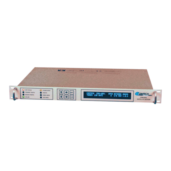
Chapter 1. INTRODUCTION The CDM-600L (Figure 1-1) is an Open Network Satellite Modem, intended for both Intelsat and closed network applications. • It is compliant with IESS-308/309/310/315 specifications, but also adds significant other features in closed network modes. • It offers variable data rates from 2.4 to 20 Mbps, in BPSK, QPSK, Offset QPSK, 8-PSK, 8-QAM and 16-QAM modes. -
Page 24: Standard Features
CDM-600L Satellite Modem Revision 2 Introduction MN/CDM600L.IOM Standard Features The CDM-600L provides a wealth of standard features which go far beyond the basic requirements of the Intelsat specifications. • Low rate variable data rates – 2.4 kbps to 5.0 Mbps •... -
Page 25: Verification
When normal operation is again selected, all of the previous values are restored. 1.1.4 Data Interfaces The CDM-600L includes, as standard, a universal data interface that eliminates the need to exchange interface cards for different applications. The interfaces offered include: • RS-422 (RS-530) DCE (at rates up to 10 Mbps) •... -
Page 26: Fast Options And Hardware Options
MN/CDM600L.IOM FAST Options and Hardware Options The CDM-600L is extremely flexible and powerful, and incorporates a large number of optional features. Some customers may not require all of these features, and therefore, in order to permit a lower initial cost, the modem may be purchased with only the desired features enabled. -
Page 27: Fast Accessible Options
These techniques allow the use of a unique access code to enable configuration of the available hardware. The access code can be purchased at any time from Comtech EF Data. Once obtained, the access code is loaded into the unit through the front panel keyboard or the rear remote port. -
Page 28: Implementation
1.3.4 Hardware Options There are seven hardware options available. There are two Comtech EF Data Turbo Product Codecs, and a combination TPC(Turbo) and Low-Density Parity Check (LDPC) codec, representing a very significant development in the area of FEC. They are plug-in daughter cards (SIMM modules), field upgradeable. -
Page 29: Supporting Hardware And Software
1.3.5 Supporting Hardware and Software The CDM-600L incorporates an FSK serial link that can be activated on the TX-IF port for the purpose of communicating with an FSK capable BUC. In this manner, a user may monitor, configure, and control the BUC using the front panel display and keypad of the modem or the modem’s remote control interface. - Page 30 * A Power-On, Carrier-Off (POCO) feature has been added to the Factory Menu. * When this option is set to OFF, the CDM-600L will power-up with the Tx Carrier in the last known state. (For example, if the Tx Carrier was ON, and then the power is cycled, the Tx Carrier will be turned ON once more.)
-
Page 31: Chapter 2. Installation
Chapter 2. INSTALLATION Unpacking Inspect shipping containers for damage. If shipping containers are damaged, keep them until the contents of the shipment have been carefully inspected and checked for normal operation. The modem and manual are packaged in pre-formed, reusable, cardboard cartons containing foam spacing for maximum shipping protection. -
Page 32: Mounting
MN/CDM600L.IOM Mounting If the CDM-600L is to be mounted in a rack, ensure that there is adequate clearance for ventilation, particularly at the sides. In rack systems where there is high heat dissipation, forced air cooling must be provided by top or bottom mounted fans or blowers. Under no circumstance should the highest internal rack temperature be allowed to exceed 50°C... -
Page 33: Figure 2-1. Installation Of The Optional Mounting Bracket, Kt/6228-2
CDM-600L Satellite Modem Revision 2 Installation MN/CDM600L.IOM Equipment Rack Mounting Rail #10 Socket head screw BRACKET BOLTS Support Bracket Bracket #10 Flat Washer #10 Hex Nut Back of Modem * Note: Components of mounting kit KT/6228-1 Figure 2-1. Installation of the Optional Mounting Bracket, KT/6228-2... -
Page 34: Configuration
–130 + 10log(symbol rate) dBm to -130 + 10log(symbol rate) +50 dBm. The CDM-600L includes an internal programmable 13, 18, or 24V LNB power supply at the receive IF connector, and optionally includes a 24 or 48V BUC power supply at the transmit IF connector. -
Page 35: Chapter 3. Functional Description
Chapter 3. FUNCTIONAL DESCRIPTION The CDM-600L has two fundamentally different types of interface - IF and data. • The data interface is a bi-directional path which connects with the customer’s equipment (assumed to be the DTE) and the modem (assumed to be the DCE). -
Page 36: Figure 3-1. Cdm-600L Modem Block Diagram
DTE equipment. Physically the CDM-600L modem is comprised of two main card assemblies. • The first of these is the baseband framer card, which includes all of the interface circuits, the framer/de-framer, plesiochronous/Doppler buffer, Reed Solomon outer codec, and the main microcontroller. -
Page 37: Chapter 4. Physical Description
DESCRIPTION Introduction The CDM-600L is constructed as a 1U high rack-mounting chassis, which can be free- standing, if desired. Rack handles at the front facilitate removal from and placement into a rack. Figure 4-1 shows the front panel of the modem. -
Page 38: Rear Panel
Modem with AC Input Power Modem with DC Input Power Figure 4-2. CDM-600L Rear Panel External cables are attached to connectors on the rear panel of the CDM-600L. These comprise: • IEC line input connector for AC power, or Corcom PS000DD6D for DC power •... - Page 39 CDM-600L Satellite Modem Revision 2 Physical Description MN/CDM600L.IOM IEC AC line input connector The IEC line input connector contains the ON/OFF switch for the unit. It is also fitted with two fuses - one each for line and neutral connections (or L1, L2, where appropriate).
- Page 40 CDM-600L Satellite Modem Revision 2 Physical Description MN/CDM600L.IOM Overhead connector (P3A) The Overhead connector is a 25-pin ‘D’ type male (DB25-M). It is used for passing components of INTELSAT specified overhead frame structures. These include 64 kbps RS-422 and 1/16 IBS overhead ESC at RS-232. The IDR backward alarm inputs are found on this connector.
- Page 41 CDM-600L Satellite Modem Revision 2 Physical Description MN/CDM600L.IOM Balanced G.703 connector Tx/Rx connector (P7) A 15-pin 'D' type female (DB15-F) for balanced operation at the G.703 data rates of T1 (1.544 Mbps), E1 (2.048 Mbps), or T2 (6.312 Mbps). Unbalanced G.703 Tx/Rx (J10B and J11B) Two female BNC 75Ω...
-
Page 42: Dimensional Envelope
CDM-600L Satellite Modem Revision 2 Physical Description MN/CDM600L.IOM Dimensional Envelope 18.0 1.72 16.53 19.0 Figure 4-3. CDM-600L Dimensional Envelope 4–6... -
Page 43: Chapter 5. Connector Pinouts
Chapter 5. CONNECTOR PINOUTS Connector Overview The rear panel connectors (Figure 5-1) provide all necessary external connections between the modem and other equipment. 5–1... -
Page 44: Table 5-1. Cdm-600L External Connections
CDM-600L Satellite Modem Revision 2 Connector Pinouts MN/CDM600L.IOM Figure 5-1. CDM-600L Rear Panel Table 5-1. CDM-600L External Connections Name Connector Type Function RX IF RF Input TX IF RF Output Aux Serial USB Type B (female) Auxiliary Serial Overhead 25-pin D (male) -
Page 45: Overhead Interface Connector (P3A)
CDM-600L Satellite Modem Revision 2 Connector Pinouts MN/CDM600L.IOM Overhead Interface Connector (P3A) The overhead interface connector is a 25-pin male D interface located on the rear panel of the modem. Refer to Table 5-2 for pin assignments. Table 5-2. Overhead Interface Connector Pin Assignments... -
Page 46: Data Interface Connector (P3B)
CDM-600L Satellite Modem Revision 2 Connector Pinouts MN/CDM600L.IOM Data Interface Connector (P3B) The Data Interface connector, a 25-pin D type female, conducts data input and output signals to and from the modem, and connects to customer’s terrestrial equipment, breakout panel, or protection switch. Refer to Table 5-3 for pin assignments. -
Page 47: Audio Interface Connector (P4A)
CDM-600L Satellite Modem Revision 2 Connector Pinouts MN/CDM600L.IOM Audio Interface Connector (P4A) The Audio interface connection is a 9-pin female D connector located on the rear panel of the modem. Refer to Table 5-4 for pin assignments. Table 5-4. Audio Interface Connector Pin Assignments... -
Page 48: Idr Backward Alarms Connector (P5A)
CDM-600L Satellite Modem Revision 2 Connector Pinouts MN/CDM600L.IOM IDR Backward Alarms Connector (P5A) The IDR Alarm interface connection is a 15-pin female connector located on the rear panel of the modem. Refer to Table 5-6 for pin assignmernts. Table 5-6. IDR Alarm Interface Connector Pin Assignments... -
Page 49: Balanced G.703 Interface Connector (P7)
CDM-600L Satellite Modem Revision 2 Connector Pinouts MN/CDM600L.IOM Balanced G.703 Interface Connector (P7) The Balanced G.703 connection is a 15-pin female connector located on the rear panel of the modem. Refer to Table 5-8 for pin assignments. Table 5-8. Balanced G.703 Interface Connector Pin Assignments... -
Page 50: Unit Alarms (P5B)
CDM-600L Satellite Modem Revision 2 Connector Pinouts MN/CDM600L.IOM 5.10 Unit Alarms (P5B) Unit alarms are provided on a 15-pin male connector located on the rear panel of the modem. Refer to Table 5-10 for pin assignments. Table 5-10. Alarm Interface Connector Pin Assignments... -
Page 51: Dc Power Connector Option
CDM-600L Satellite Modem Revision 2 Connector Pinouts MN/CDM600L.IOM 5.12 DC Power Connector Option A detachable, locking, 2-prong power cord supplies the Direct Current (DC) power to the modem. Observe the following: DC Power Specifications Input Power 250W maximum, 55W typical without BUC power supply. - Page 52 CDM-600L Satellite Modem Revision 2 Connector Pinouts MN/CDM600L.IOM NOTES: 5–10...
-
Page 53: Chapter 6. Front Panel Operation
Description Figure 6-1. Front Panel View The user can fully control and monitor the operation of the CDM-600L from the front panel, using the keypad and display. Nested menus are used, which display all available options, and prompt the user to carry out a required action. -
Page 54: Table 6-1. Front Panel Led Indicators
CDM-600L Satellite Modem Revision 2 Front Panel Operation MN/CDM600L.IOM If the user were to display the same screen for weeks at a time, the display could become ‘burnt’ with this image. To prevent this, the unit has a ‘screen saver’ feature which will activate after 1 hour. -
Page 55: Figure 6-2. Keypad
CDM-600L Satellite Modem Revision 2 Front Panel Operation MN/CDM600L.IOM Figure 6-2. Keypad The function of these keys is as follows: ENTER This key is used to select a displayed function or to execute a modem configuration change. CLEAR This key is used to back out of a selection or to cancel a configuration change which has not been executed using [ENTER]. -
Page 56: Figure 6-3. Cdm-600L Menu Trees
BUC-FSK FSK LINK, TX OUTPUT, LEVELING, ADDRESS BUC-LO BUC-CONFIG PWR, 10MHz, ALARM CIRCUITS, PW R-UP DELAY LNB-CONFIG BUC-LO LO FREQ. MIX LNB-LO LNB-CONFIG VOLTAGE, PW R, 10MHz, ALARM LIMIT LNB-LO LO FREQ. MIX FAST Figure 6-3. CDM-600L Menu Trees 6–4... -
Page 57: Opening Screen
CDM-600L Satellite Modem Revision 2 Front Panel Operation MN/CDM600L.IOM Opening Screen This screen is displayed whenever power is first applied to the unit: COMTECH CDM-600L OPEN NETWORK MODEM TURBO: TPC/LDPC S/W VER 1.3.0 The bottom line displays which Turbo codec (if any) is installed, and the internal software version. -
Page 58: Config
CDM-600L Satellite Modem Revision 2 Front Panel Operation MN/CDM600L.IOM 6.3.1 CONFIG CONFIG: MODE CLOCKS D&I FREQ-REF EDMAC MISC REMOTE MASK STATS The sub-branches available are: Permits the user to completely configure the unit, being prompted, step by step, to make choices, or edit data. This is highly recommended for new users, as it will clearly lead the user through all the configuration parameters. - Page 59 CDM-600L Satellite Modem Revision 2 Front Panel Operation MN/CDM600L.IOM 6.3.1.1 CONFIG: ALL ALL = START (STOP, START) Use the [↑] and [↓] arrow keys to select START or STOP, then press ENTER. The user may then configure the unit, in a step-by-step process by viewing each menu in succession.
- Page 60 CDM-600L Satellite Modem Revision 2 Front Panel Operation MN/CDM600L.IOM The AUDIO choice permits the user to carry 2 x 32 kbps ADPCM audio as the primary data. This interface type forces IBS or EDMAC as the available framing types. The second option is the Framing type.
- Page 61 CDM-600L Satellite Modem Revision 2 Front Panel Operation MN/CDM600L.IOM RTI means RECEIVE/TRANSMIT INHIBIT. When selected, it will prevent the TX carrier from being transmitted, until the demodulator is IMPORTANT locked. To avoid the TX Carrier from being turned off when the demodulator loses lock for a very short period of time, the demodulator must be unlocked continuously for a period of 10 seconds before the transmit carrier is inhibited.
- Page 62 CDM-600L Satellite Modem Revision 2 Front Panel Operation MN/CDM600L.IOM Use the [←] [→] arrow keys to select either TARGET-EbNo/RANGE or ALARM ACTION, then press ENTER If TARGET-EbNo/RANGE is selected, the following menu will be displayed: MINIMUM EbNo OF REMOTE MODEM = 5.0dB...
- Page 63 EDMAC (200/180), closed network • IDR (225/205), open network • IDR (194/178), open network • UNFRAMED (220/200), closed network • LEGACY COMTECH EF DATA (225,205, with V.35 scrambling), closed network CONFIG: TX: MODULATION MODULATION = QPSK (B,Q,OQ,8-PSK,16QAM) FEC RATE = 1/2 (1/2,3/4,7/8) 6–11...
- Page 64 CDM-600L Satellite Modem Revision 2 Front Panel Operation MN/CDM600L.IOM Select one of the parameters using the [←] [→] arrow keys, and then edit using the [↑] [↓] arrow keys. Edit the Modulation type and the FEC rate. The Modulation Type and FEC rate choices are dictated by the Encoder type:...
- Page 65 CDM-600L Satellite Modem Revision 2 Front Panel Operation MN/CDM600L.IOM When Drop Framing or the G.703 interface type is used the [↑] [↓] arrow keys will scroll through the available data rates. If in Drop Mode and the data rate is edited to 1920 kbps, a comment is shown to indicate that E1 fixed channel mode will be implemented.
- Page 66 CDM-600L Satellite Modem Revision 2 Front Panel Operation MN/CDM600L.IOM CONFIG: RX: RX-IF ACQUISITION SWEEP RANGE = +/- 10 kHz RX FREQ=1200.0000MHz SPECTRUM INVERT=OFF Edit the Acquisition Sweep Range of the demodulator. The value of the digit is changed using the [↑] [↓] arrow keys. Press ENTER.
- Page 67 • IDR (194/178), open network • UNFRAMED (220/200), closed network • LEGACY COMTECH EF DATA (225,205, with V.35 scrambling), closed network CONFIG: RX: DEMODULATION DEMODULATION=QPSK(B,Q,OQ,8-PSK,16QAM) FEC RATE = 1/2 (1/2,3/4,7/8) Select one of the parameters using the [←] [→] arrow keys, and then edit using the [↑] [↓] arrow keys.
- Page 68 CDM-600L Satellite Modem Revision 2 Front Panel Operation MN/CDM600L.IOM The Demodulation Type FEC Rate choices are dictated by the Decoder type: No Decoder: BPSK Fixed at 1/1 QPSK, OQPSK Fixed at 1/1 Non-Turbo Decoder: BPSK Fixed at Rate 1/2 TCM 8-PSK...
- Page 69 CDM-600L Satellite Modem Revision 2 Front Panel Operation MN/CDM600L.IOM with certain older equipment). Select either ON or OFF, using the [↑] [↓] arrow keys, then press ENTER. When G.703 is used and the Modem is Hardware Revision 2.0 or higher, three auxiliary rates will also be available (512, 1024 and 2048 kbps) indicated by the word AUX appearing to the right of the decimal place.
- Page 70 CDM-600L Satellite Modem Revision 2 Front Panel Operation MN/CDM600L.IOM 6.3.1.5 CONFIG: CLOCKS CLOCKING: TX-CLOCK RX-BUFFER/CLOCK EXTERNAL-BASEBAND-CLOCK The sub-branches available are CONFIG: CLOCKS: TX CLOCK TRANSMIT CLOCK = INTERNAL(SCT) (INT(SCT),TX-TERR(TT),RX-LOOP,EXT-CLK) Select from the choices shown in the parentheses using the [↑] [↓] arrow keys, then press ENTER.
- Page 71 CDM-600L Satellite Modem Revision 2 Front Panel Operation MN/CDM600L.IOM CONFIG:CLOCKS: RX BUFFER/CLOCK CLK= RX-SAT (RX-SAT,TX-TERR,EXT-CLK,INS) BUFFER-SIZE = 00016bytes(00002ms) CENTER sing the [←] [→] arrow keys keys, select one of the three parameters on the screen to edit. Edit the RX clock options using the [↑] [↓] arrow keys, then press ENTER...
-
Page 72: Chapter 10. Clock Modes And Drop And Insert (D&I)
CDM-600L Satellite Modem Revision 2 Front Panel Operation MN/CDM600L.IOM If CENTER is selected, the following sub-menu is displayed: CONFIG: CLOCKS: RX BUFFER/CLOCK: CENTER PRESS ENTER TO CENTER THE BUFFER OTHERWISE, PRESS CLEAR Follow the instructions on the screen. CONFIG: CLOCKS: EXTERNAL-BASEBAND-CLOCK EXTERNAL-BASEBAND-CLOCK = 02048.000 kHz... - Page 73 CDM-600L Satellite Modem Revision 2 Front Panel Operation MN/CDM600L.IOM To edit the Channel Timeslots (CHAN/TS) for either Drop or Insert, press ENTER and another screen will be shown: CONFIG: DROP & INSERT: DROP CHANNEL TIMESLOTS DRP-CH: 1 TS: 01 Select the Time-slot to edit using the [←] [→]arrow keys and edit the value using the [↓] [↑] arrow keys, then press ENTER.
- Page 74 CDM-600L Satellite Modem Revision 2 Front Panel Operation MN/CDM600L.IOM An EDMAC MASTER is a unit which is local to the M&C computer, and which passes messages, via the overhead, to a distant-end modem. The MASTER address will always end in 0.
- Page 75 CDM-600L Satellite Modem Revision 2 Front Panel Operation MN/CDM600L.IOM This menu permits a user to decide if the 64 kbps channel in the IDR overhead (normally reserved for the two 32 kbps ADPCM audio channels) should carry user data instead. The rear panel Overhead connector provides the appropriate RS-422 interface for this option.
- Page 76 CDM-600L Satellite Modem Revision 2 Front Panel Operation MN/CDM600L.IOM For units with Firmware Version 1.3.0 or greater: ESC++ is available as standard. If enabled, the lower of the Tx or Rx primary data rate limits that maximum ESC baud rate, according to the table below.
- Page 77 CDM-600L Satellite Modem Revision 2 Front Panel Operation MN/CDM600L.IOM CONFIG: REMOTE CONTROL: CHAR FORMAT PARITY:DATA-BITS:STOP-BITS = N81 (N81,E72,O72) Edit the I/O character format using the [↑] [↓] arrow keys. The options are: No parity 8 Data bits 1 Stop bit...
- Page 78 CDM-600L Satellite Modem Revision 2 Front Panel Operation MN/CDM600L.IOM CONFIG: MASK: BUFFER SLIP BUFFER SLIP= ACTIVE (ACTIVE,MASK) Select either ACTIVE or MASKED, using the [↑] [↓] arrow keys, then press ENTER. If the user selects ACTIVE, then a Buffer Slip fault will be generated whenever the receive circuitry senses that the buffer has either underflowed, or overflowed.
- Page 79 CDM-600L Satellite Modem Revision 2 Front Panel Operation MN/CDM600L.IOM CONFIG: MASK: SATELLITE ALARMS: RX PROCESS ALARMS RECEIVED FROM SATELLITE BWA1=N, BWA2=N, BWA3=N, BWA4=N Select which Rx IDR backward alarms are to be monitored. CONFIG: MASK: TERR-ALM TERR-ALM: TX = ACTIVE...
-
Page 80: Test
CDM-600L Satellite Modem Revision 2 Front Panel Operation MN/CDM600L.IOM 6.3.2 TEST MODEM TEST MODE = NORMAL (NORM,TX-CW,TX-1/0,IF↓,RF↓,DIG↓,I/O↓) Select Test Mode or Normal Operation from the parameters shown in the parentheses using the [↑] [↓] arrow keys, then press ENTER. This sub-menu permits the user to select the following test modes:... -
Page 81: Figure 6-4. Loopback Modes
CDM-600L Satellite Modem Revision 2 Front Panel Operation MN/CDM600L.IOM Figure 6-4. Loopback Modes 6–29... -
Page 82: Information
CDM-600L Satellite Modem Revision 2 Front Panel Operation MN/CDM600L.IOM 6.3.3 INFORMATION INFO: ALL ID FORMAT TX RX CLOCKS EDMAC DROP INSERT REMOTE ALARM-MASK MISC Select information to view using the [←][→] arrow keys, then press ENTER. Note: INFO screens display information on the current configuration of the modem without risking inadvertent changes. - Page 83 CDM-600L Satellite Modem Revision 2 Front Panel Operation MN/CDM600L.IOM 6.3.3.4 INFO: TX TX:ON 1200.0000MHz PWR=-10.0 TSI=N VIT+RS:220/220 00604.000 QPSK 1/2 SCRM A sample display of TX Info is shown. The information displayed here is as follows: Top Line: TX carrier...
- Page 84 CDM-600L Satellite Modem Revision 2 Front Panel Operation MN/CDM600L.IOM 6.3.3.6 INFO: CLOCKS CLOCKS:TX=INT(SCT) RX=EXT-CLK REF=INT10 BUFFER-SIZE=00016 CLK=02048U The TX Clock, RX Clock, Reference and Buffer information is displayed. Note: The clock information on the lower line in only shown if RX clock is set to EXT- CLK.
- Page 85 CDM-600L Satellite Modem Revision 2 Front Panel Operation MN/CDM600L.IOM 6.3.3.10 INFO: REMOTE REMOTE-CONTROL= LOCAL ADDRESS= 0000 INTERFACE = RS-232 9600 BAUD N81 This screen shows if the unit is in Local or Remote mode, provides the details of the electrical interface type selected, the unit’s address and the baud rate selected. Pressing ENTER takes the user back to the previous menu.
-
Page 86: Monitor
CDM-600L Satellite Modem Revision 2 Front Panel Operation MN/CDM600L.IOM 6.3.4 MONITOR MONITOR: LIVE-ALARMS STORED-EVENTS STATISTICS RX-PARAMS AUPC-PARAM Select the parameter to Monitor using the [←][→] arrow keys, then press ENTER. 6.3.4.1 MONITOR: LIVE-ALARMS LIVE UNIT= NONE NET= NONE ALARMS RECV=DEMOD LOCK XMT= NONE An example of an Alarm screen is shown. - Page 87 CDM-600L Satellite Modem Revision 2 Front Panel Operation MN/CDM600L.IOM OPEN NETWORK LOSE TxFRM Loss of Tx frame occurs in Drop & Insert operation, when the incoming T1 or E1 frame cannot be found by the modem. BER>10E-3 This error rate monitor is enabled for IBS and IDR framing.
- Page 88 CDM-600L Satellite Modem Revision 2 Front Panel Operation MN/CDM600L.IOM The top line displays the log entry number and event log.The bottom line of the display indicates the time and date of the entry shown in DAY-MONTH-YEAR format. The display shows the statistics data that has been measured and recorded. The statistics logs can store up to 199 log entries.
- Page 89 CDM-600L Satellite Modem Revision 2 Front Panel Operation MN/CDM600L.IOM 6.3.4.4 MONITOR: RX PARAMETERS ∆F=+11.7kHz RX=PARAMETERS: EbNo=11.4dB BER=0.0E-9 BUFFER=51% RX-LEVEL=-43dBm If the demodulator is locked, this screen shows the following: Eb/No This shows the value of Eb/No calculated by the demodulator. The value referred to here is the energy per information bit (Ebi), divided by the noise spectral density (No).
- Page 90 CDM-600L Satellite Modem Revision 2 Front Panel Operation MN/CDM600L.IOM 6.3.4.6 MONITOR: LNB LNB: CURRENT = xxx mA Voltage = xx V The monitor display shows the measured LNB current load and LNB voltage at the receive IF connector. 6.3.4.7 MONITOR:BUC BUC:CURRENT = 0000mA VOLT = 47.9V CLASS = N/A...
-
Page 91: Store/Load
CDM-600L Satellite Modem Revision 2 Front Panel Operation MN/CDM600L.IOM 6.3.5 STORE/LOAD CONFIGURATION: 0 LOAD STORE EDIT 'AVAILABLE' Select LOAD, STORE or EDIT using the [←][→] arrow keys, then press ENTER. The user can store, load up to 10 different modem configurations, or record the date and time of stored configurations in the non-volatile memory of the modem. -
Page 92: Utilities
CDM-600L Satellite Modem Revision 2 Front Panel Operation MN/CDM600L.IOM 6.3.6 UTILITIES UTILITIES: SET-RTC DISPLAY-BRIGHTNESS LAMP 1:1-MANUAL-SWITCH EDIT-CIRCUIT-ID Select the Utilities parameter using the [←][→] arrow keys, then press ENTER 6.3.6.1 UTILITIES: SET-RTC EDIT REAL-TIME CLOCK: TIME: 12:00:00 DATE: 24/04/01 To edit the time and date settings of the REAL-TIME CLOCK, select the digit to be edited using the [←][→] arrow keys, change the value of the digit using the [↑] [↓] arrow keys,... - Page 93 CDM-600L Satellite Modem Revision 2 Front Panel Operation MN/CDM600L.IOM 6.3.6.4 UTILITIES: 1:1 MANUAL SWITCH PRESS ENTER KEY TO FORCE UNIT INTO STANDBY (1:1 ONLY) If the unit is part of a 1:1 redundant pair of modems, and this unit, is currently on-line, pressing ENTER will cause the unit to switch to standby.
-
Page 94: Odu
MN/CDM600L.IOM 6.3.7 The ODU menu allows the user to access an FSK menu that permits the CDM-600L to interface directly with an FSK-capable BUC. The interface is accomplished using a low- speed, half-duplex FSK link on the TX IF port, with a carrier frequency around 650 kHz. - Page 95 CDM-600L Satellite Modem Revision 2 Front Panel Operation MN/CDM600L.IOM 6.3.7.1 ODU: BUC-FSK FSK: LINK =OFF TX–OUTPUT=N/A LEVELING=N/A ADDRESS=N/A Select a parameter to edit using the [←] [→] arrow keys. LINK Turns the FSK communications with the BUC ON and OFF. Use [↑] [↓] arrow keys to select ON and OFF and press ENTER.
- Page 96 CDM-600L Satellite Modem Revision 2 Front Panel Operation MN/CDM600L.IOM ODU: BUC-LO BUC-LO: FREQUENCY = 00000 MHz MIX = HIGH (-) Select a parameter to edit using the [←] [→] arrow keys. FREQUENCY Sets the LO frequency in the BUC for the up conversion. Entering a...
- Page 97 CDM-600L Satellite Modem Revision 2 Front Panel Operation MN/CDM600L.IOM ODU: LNB-LO LNB-LO: FREQUENCY = 00000 MHz MIX = HIGH (-) Select a parameter to edit using the [←] [→] arrow keys. FREQUENCY Sets the LO frequency in the LNB for the downconversion. Entering a...
-
Page 98: Fast
FAST is the way to enable new options in the modem. Obtain the FAST code for the new option from Comtech EF Data. Enter the code carefully. Use the [←][→] arrow keys to move the cursor to each character. Use the [↑] [↓] arrow keys to edit the character, then press ENTER. -
Page 99: Chapter 7. Forward Error Correction Options
Turbo Coding represents a very significant development in the area of FEC, and optionally, the CDM-600L may be fitted with one of three Turbo Product Codecs They are plug-in daughter cards (SIMM modules), both field upgradeable. The Low Rate option provides data rate capability up to 5 Mbps, and code rates limited to Rate 5/16 (BPSK, Rate 21/44 (BPSK) and Rate 3/4 (QPSK, OQPSK, 8-PSK and 16-QAM). -
Page 100: Sequential
Eb/No). This is not true of the Sequential decoding method, as explained in the section below. Note that in BPSK mode, the CDM-600L only permits a coding rate of 1/2. Because the method of convolutional coding used with Viterbi, the encoder does not preserve the original data intact, and is called non-systematic. -
Page 101: Reed-Solomon Outer Codec
Sequential decoder is spread out over a number of interleaving frames, so errors entering the Reed-Solomon decoder do not exceed its capacity to correct those errors. In the case of the CDM-600L, different Reed-Solomon code rates are used, according to the mode of operation: 7–3... -
Page 102: Table 7-3. Concatenated Reed-Solomon Coding Summary
This may be due to the carrier-recovery circuits, or the synchronization threshold of the primary FEC device, or both. In the CDM-600L, and Rate 1/2 operation, this threshold is around 4 dB Eb/No. Below this value, operation is not possible, but above this value, the error performance of the concatenated Reed-Solomon system produces exceptionally low error rates for a very small increase in Eb/No. -
Page 103: Trellis Coding (Fast Option)
– the natural consequences of the higher-order modulation. The CDM-600L fully implements the IESS-310 specification at data rates up to 20 Mbps. In accordance with the specification, the Reed-Solomon outer code can be disabled. -
Page 104: Turbo Product Codec (Hardware Option)
Turbo Codes have been developed, Turbo Convolutional Codes (TCC), and Turbo Product Codes (TPC, a block coding technique). Comtech EF Data has chosen to implement an FEC codec based on TPC. A Turbo Product Code is a 2 or 3 dimensional array of block codes. -
Page 105: Ldpc Versus Tpc
In order to take full advantage of the coding gain increase that LDPC provides, it became necessary to find an alternative to 8-PSK. Comtech EF Data has therefore developed an 8- QAM approach that permits acquisition and tracking at much lower values of Eb/No than 8- PSK. -
Page 106: Table 7-5. Available Tpc And Ldpc Modes
1/2 to 0.95, both an LDPC and a TPC codec need to be offered. In order to meet this requirement, Comtech EF Data has developed a combination LDPC/TPC Codec module that can be added to the CDM-600L Modem, and which provides the following operating modes: Table 7-5. -
Page 107: 7.7.3 End-To-End Processing Delay
Forward Error Correction Options MN/CDM600L.IOM This new LDPC/TPC codec module may be installed in any existing CDM-600L, as a simple field upgrade, or already installed in new modems ordered from the factory. It requires Firmware Version 1.3.0 (or higher) to be installed. - Page 108 * The occupied bandwidth is defined at the width of the transmitted spectrum taken at the –10 dB points on the plot of power spectral density. This equates to 1.19 x symbol rate for the CDM-600L transmit filtering. ** Included for comparative purposes...
-
Page 109: Uncoded Operation (No Fec)
There are occasions where a user may wish to operate a satellite link with no forward error correction of any kind. For this reason, the CDM-600L offers this uncoded mode for three modulation types - BPSK, QPSK, and OQPSK. However, the user should be aware of some of the implications of using this approach. - Page 110 Example 2: A Firmware Version of 1.3.0, or higher is used. There is no limitation on acquisition sweep width. Comtech EF Data cannot be held responsible for incorrect operation if the user does not adhere to these guidelines when using uncoded operation.
-
Page 111: Figure 7-1. Viterbi Decoding
CDM-600L Satellite Modem Revision 2 Forward Error Correction Options MN/CDM600L.IOM Eb/No in dB 1E-1 Uncoded BPSK/QPSK Viterbi Decoding 1E-2 Typical Performance 1E-3 1E-4 1E-5 1E-6 Specification limit, Rate 7/8 1E-7 Coding 1E-8 Specification Specification limit Rate 1/2 limit, Rate 3/4... -
Page 112: Figure 7-2. Sequential Decoding 64 Kbps
CDM-600L Satellite Modem Revision 2 Forward Error Correction Options MN/CDM600L.IOM Eb/No in dB 1E-1 Sequential Uncoded BPSK/QPSK Decoding 64 kbps 1E-2 Typical 1E-3 Performance 1E-4 1E-5 1E-6 Specification 1E-7 limit, Rate 7/8 Coding 1E-8 Specification Specification limit Rate 1/2 limit, Rate 3/4... -
Page 113: Figure 7-3. Sequential Decoding 1024 Kbps
CDM-600L Satellite Modem Revision 2 Forward Error Correction Options MN/CDM600L.IOM Eb/No in dB 1E-1 Sequential Uncoded BPSK/QPSK Decoding 1024 kbps 1E-2 1E-3 Typical Performance 1E-4 1E-5 1E-6 Specification 1E-7 limit, Rate 7/8 Coding 1E-8 Specification limit Rate 1/2 Specification Coding... -
Page 114: Figure 7-4. Sequential Decoding 2048 Kbps
CDM-600L Satellite Modem Revision 2 Forward Error Correction Options MN/CDM600L.IOM Eb/No in dB 1E-1 Sequential Uncoded BPSK/QPSK Decoding 2048 kbps 1E-2 1E-3 1E-4 1E-5 1E-6 Typical performance, Rate 7/8 Coding 1E-7 1E-8 Typical Typical performance, performance, Rate 3/4 Rate 1/2... - Page 115 CDM-600L Satellite Modem Revision 2 Forward Error Correction Options MN/CDM600L.IOM Eb/No in dB 1E-1 Viterbi with Uncoded BPSK/QPSK concatenated RS 220,200 1E-2 Outer Code Sync threshold, Rate 3/4 1E-3 Sync threshold, Rate 7/8 1E-4 Combined sync 1E-5 threshold, demod and Viterbi...
- Page 116 CDM-600L Satellite Modem Revision 2 Forward Error Correction Options MN/CDM600L.IOM Eb/No in dB 1E-1 Sequential Uncoded BPSK/QPSK with concatenated 1E-2 RS 220,200 Outer Code 512 kbps 1E-3 1E-4 Combined sync threshold, demod and Sequential 1E-5 Decoder, Rate 1/2 Sync threshold,...
-
Page 117: Figure 7-7. 8-Psk/Tcm Rate 2/3 With And Without Concatenated Reed-Solomon Outer Code
CDM-600L Satellite Modem Revision 2 Forward Error Correction Options MN/CDM600L.IOM Eb/No in dB 1E-1 8-PSK/TCM Rate 2/3 Uncoded BPSK/QPSK Decoding, with and without 219, 201 RS 1E-2 Outer Code Performance with CDM-600 Firmware Version 1.1.5 (or higher) 1E-3 1E-4 Typical... -
Page 118: Figure 7-8. Comtech Ef Data Turbo Product Codec Rate 3/4 Qpsk/Oqpsk, 8-Psk And 16-Qam
Spec limit Rate 3/4 Uncoded 8-PSK 8-PSK 1E-4 Spec limit Rate 3/4 QPSK/OQPSK 1E-5 1E-6 1E-7 Spec limit Rate 3/4 16-QAM 1E-8 Typical performance 1E-9 Figure 7-8. Comtech EF Data Turbo Product Codec Rate 3/4 QPSK/OQPSK, 8-PSK and 16-QAM 7–20... -
Page 119: Figure 7-9. Comtech Ef Data Turbo Product Codec Rate 7/8 Qpsk/Oqpsk, 8-Psk And 16-Qam
Spec limit Rate 7/8 Spec limit 8-PSK Rate 7/8 Uncoded QPSK/OQPSK 8-PSK 1E-4 1E-5 1E-6 1E-7 Spec limit Rate 7/8 16-QAM 1E-8 Typical performance 1E-9 Figure 7-9. Comtech EF Data Turbo Product Codec Rate 7/8 QPSK/OQPSK, 8-PSK and 16-QAM 7–21... -
Page 120: Figure 7-10. Rate 1/2 Qpsk, Rate 0.95 Qpsk And Rate 0.95 8-Psk
CDM-600L Satellite Modem Revision 2 Forward Error Correction Options MN/CDM600L.IOM Eb/No in dB 1E-1 Comtech Turbo Product Codec Rate 1/2 QPSK/OQPSK Uncoded Rate 0.95 QPSK/OQPSK BPSK/QPSK 1E-2 and 8-PSK Performance with CDM-600 Firmware Version 1.1.5 (or higher) Uncoded 8-PSK 1E-3... -
Page 121: Figure 7-11. Rate 21/44 Bpsk And Rate 5/16 Bpsk Turbo
CDM-600L Satellite Modem Revision 2 Forward Error Correction Options MN/CDM600L.IOM Eb/No in dB 1E-1 Comtech Turbo Product Codec Rate 21/44 BPSK Rate 5/16 BPSK 1E-2 Spec limit Rate 5/16 BPSK 1E-3 Spec limit Rate 21/44 BPSK 1E-4 Uncoded BPSK/QPSK 1E-5... -
Page 122: Figure 7-12. 16-Qam Viterbi, Rate 3/4 And Rate 7/8 With 220,200 Reed-Solomon Outer Code
CDM-600L Satellite Modem Revision 2 Forward Error Correction Options MN/CDM600L.IOM Eb/No in dB 1E-1 16-QAM Viterbi, Rate 3/4 and Rate 7/8 with 220,200 RS Outer Code Uncoded BPSK/QPSK 1E-2 Uncoded 16-QAM 1E-3 1E-4 Specification limit Rate 7/8 Viterbi and 220,200 RS... -
Page 123: Figure 7-13. Differential Encoding - No Fec, No Scrambling
CDM-600L Satellite Modem Revision 2 Forward Error Correction Options MN/CDM600L.IOM Eb/No in dB 1E-1 Differential Encoding - No FEC, no Uncoded BPSK/QPSK 1E-2 scrambling 1E-3 1E-4 1E-5 1E-6 1E-7 1E-8 1E-9 Figure 7-13. Differential Encoding - No FEC, No Scrambling... -
Page 124: Figure 7-14. Ldpc, Rate 1/2, Bpsk, (O)Qpsk
CDM-600L Satellite Modem Revision 2 Forward Error Correction Options MN/CDM600L.IOM Eb/No in dB 1E-1 LDPC, BPSK, QPSK, Uncoded BPSK/QPSK/ (O)QPSK, Rate 1/2 OQPSK 1E-2 1E-3 1E-4 Spec limit Rate 1/2 1E-5 BPSK/QPSK/OQPSK 1E-6 1E-7 Typical limit Rate 1/2 BPSK/QPSK/OQPSK 1E-8 1E-9 Figure 7-14. -
Page 125: Figure 7-15. Ldpc, Rate 2/3, (O)Qpsk/8-Psk/8-Qam
CDM-600L Satellite Modem Revision 2 Forward Error Correction Options MN/CDM600L.IOM Eb/No in dB 1E-1 LDPC Rate 2/3 QPSK/OQPSK/8-PSK/ 8-QAM Uncoded 1E-2 BPSK/QPSK/OQPSK 1E-3 Spec Limit Spec Limit QPSK/OQPSK 8-QAM Rate 2/3 Rate 2/3 Uncoded 1E-4 8-PSK Typical Limit 1E-5 8-QAM... -
Page 126: Figure 7-16. Ldpc, Rate 3/4, (O)Qpsk/8-Qam
CDM-600L Satellite Modem Revision 2 Forward Error Correction Options MN/CDM600L.IOM Eb/No in dB 1E-1 LDPC, Rate 3/4 QPSK/OQPSK/ Uncoded BPSK/QPSK 8-QAM 1E-2 1E-3 Spec limit Spec limit QPSK/OQPSK 8-QAM Uncoded Rate 3/4 Rate 3/4 8-PSK 1E-4 Typical limit 8-QAM Rate 3/4... -
Page 127: Figure 7-17. Ldpc, Rate 3/4, 8-Psk / 8-Qam
CDM-600L Satellite Modem Revision 2 Forward Error Correction Options MN/CDM600L.IOM Eb/No in dB 1E-1 LDPC Rate 3/4 8-PSK/16-QAM 1E-2 Uncoded 16-QAM Uncoded 8-PSK 1E-3 Spec limit 8-PSK Rate 3/4 1E-4 Spec limit 16-QAM Rate 3/4 1E-5 Tyical limit 8-PSK Rate 3/4... - Page 128 CDM-600L Satellite Modem Revision 2 Forward Error Correction Options MN/CDM600L.IOM NOTES: 7–30...
-
Page 129: Chapter 8. Offset Qpsk Operation
Chapter 8. OFFSET QPSK OPERATION Offset QPSK modulation is a variation of normal QPSK, which is offered in the CDM- 600L. Normal, bandlimited, QPSK produces an RF signal envelope that necessarily goes through a point of zero amplitude when the modulator transitions through non-adjacent phase states. - Page 130 CDM-600L Satellite Modem Revision 2 Offset QPSK Operation MN/CDM600L.IOM The two consequences of this are: 1. Acquisition may be longer, especially at low data rates. 2. The acquisition threshold is higher than for normal QPSK, although the demodulator will maintain lock down to its normal levels. The acquisition...
-
Page 131: Chapter 9. Open Network Operations
Chapter 9. OPEN NETWORK OPERATIONS Introduction This section summarizes the functionality and specifications of the various Open Network operating modes (IDR, IBS and D&I). Primary Data Rates Supported G.703 1544, 2048, 6321, 8448 kbps SD, RD RS-422, V.35, LVDS N x 64 kbps SD, RD (up to 8448 kbps) ADPCM Audio 64 kbps only, full duplex (2 Channels) -
Page 132: Ibs Clock/Data Recovery And De-Jitter
CDM-600L Satellite Modem Revision 2 Open Network Operations MN/CDM600L.IOM 9.2.1 IBS Clock/data recovery and De-jitter Performs clock and data recovery on the G.703 format. Clock de-jitter and data encoding/decoding is done as with the IDR configuration. 9.2.2 IBS Framing Multiplexes/demultiplexes the primary data in compliance with the standard IESS-309 overhead ratio of 1/15 (4 overhead bytes per 60 data bytes) and provides the rate exchanged transmit clock to the modulator portion of the base modem. -
Page 133: D&I Primary Data Interfaces
CDM-600L Satellite Modem Revision 2 Open Network Operations MN/CDM600L.IOM Asynchronous Engineering Service Channel ESC Data Interface Type RS-232, Asynchronous ESC Data Rate 1/2000 of primary data rate ESC Data Circuits Supported SD, RD, DSR Synchronous Engineering Service Channel ESC Data Interface Type... -
Page 134: Idr
CDM-600L Satellite Modem Revision 2 Open Network Operations MN/CDM600L.IOM Primary Data Rates Supported G.703 1544 kbps SD, RD RS-422 (Replaces 8K Overhead) 2048 kbps SD, RD V.35 (Replaces 8K Overhead) 6312 kbps SD, RD 8448 kbps SD, RD Engineering Service Channel... -
Page 135: Idr Primary Data Interfaces
CDM-600L Satellite Modem Revision 2 Open Network Operations MN/CDM600L.IOM 9.4.1 IDR Primary Data Interfaces When configured for IDR operation, the board performs these functions: • Receives and performs clock and data recovery on incoming G.703 T1 and E1 pseudo-ternary data. - Page 136 CDM-600L Satellite Modem Revision 2 Open Network Operations MN/CDM600L.IOM NOTES: 9–6...
-
Page 137: Transmit Clocking
It is optional whether the DTE also returns the clock (Terminal Timing, or TT) - the modem can accept it if it is present, but uses ST if it is not. At rates above 2 Mbps, Comtech EF Data highly recommends that the user returns TT to ensure the correct clock/data relationship. -
Page 138: Tx Terrestrial Clock
10.1.4 RX Loop-Timed, RX<>TX (Asymmetric Loop Timing) The CDM-600L incorporates circuitry which permits loop timing when the TX and RX data rates are not the same. In this case the clock frequency appearing at ST will be whatever the TX data rate is programmed to, but phase-locked to the demodulator’s receive symbol clock. -
Page 139: External Reference
External Reference is also enabled, the ST clock will be locked to the external reference. 10.2 Receive Clocking There are three receive clocking modes in the CDM-600L, plus an additional setting used for Drop and Insert only – see later section. 10.2.1... -
Page 140: Figure 10-1 Tx Clock Modes
CDM-600L Satellite Modem Revision 2 Clock Modes and Drop and Insert (D&I) MN/CDM600L.IOM Figure 10-1 Tx Clock Modes 10–4... -
Page 141: Figure 10-2 Rx Clock Modes
CDM-600L Satellite Modem Revision 2 Clock Modes and Drop and Insert (D&I) MN/CDM600L.IOM Figure 10-2 Rx Clock Modes 10–5... -
Page 142: Drop And Insert
CDM-600L Satellite Modem Revision 2 Clock Modes and Drop and Insert (D&I) MN/CDM600L.IOM 10.4 Drop and Insert The Drop and Insert multiplexer works in conjunction with the G.703 interfaces to enable the modem to transmit or receive fractional parts of a T1 or E1 data stream. -
Page 143: Time Slot Selection
CDM-600L Satellite Modem Revision 2 Clock Modes and Drop and Insert (D&I) MN/CDM600L.IOM 10.6 Time Slot Selection Selection of the transmit and receive data rates may be made in certain 64 kbps increments and may be independent of each other. The actual satellite rates for open network D&I are 16/15 of the transmit or receive data rate to include IBS overhead per... -
Page 144: Drop And Insert Clocking
10.7 Drop and Insert Clocking The general arrangement for Drop and Insert clocking in the CDM-600L is shown below: Figure 10-4 Drop and Insert Clocking Note that are two inputs and two outputs shown for Drop and Insert Operation. These are: •... -
Page 145: Rx Buffer Clock = Insert (D&I Only)
CDM-600L Satellite Modem Revision 2 Clock Modes and Drop and Insert (D&I) MN/CDM600L.IOM 10.8 Rx Buffer Clock = Insert (D&I only) The E1 or T1 clock recovery from the IDI G.703 port serves as the Rx Buffer reference. In addition, the recovered data is the E1/T1 input to the Insert Mux. If the Rx G.703 recovery circuit detects no activity at IDI input, or cannot detect the expected frame format, Buffer Clock = Rx Satellite will be chosen as a fall-back. -
Page 146: Figure 10-5. Single-Source Multiple Modems (Looming)
CDM-600L Satellite Modem Revision 2 Clock Modes and Drop and Insert (D&I) MN/CDM600L.IOM - - - - - - - - - - Receive BIT ERROR TEST ___________ Transmit Figure 10-5. Single-Source Multiple Modems (Looming) MODEM MODEM MODEM Multiple Modem Drop & Insert Application: This application shows how the loop is extended to one or more additional modems. -
Page 147: Chapter 11. Edmac Channel
Chapter 11. EDMAC CHANNEL 11.1 Theory Of Operation As explained earlier, EDMAC is an acronym for Embedded Distant-end Monitor And Control. This is a feature which permits the user to access the M&C features of modems which are at the distant-end of a satellite link. This is accomplished by adding extra information to the user’s data, but in a manner which is completely transparent to the user. -
Page 148: M&C Connection
CDM-600L Satellite Modem Revision 2 EDMAC Channel MN/CDM600L.IOM known state. In the receiver, having synchronised to the frame, the de-scrambler can begin its processing at exactly the right time. This method does not multiply errors, and therefore has a clear advantage over V.35 scrambling. This is fortunate, as there is a penalty to be paid for adding the framing. -
Page 149: Setup Summary
CDM-600L Satellite Modem Revision 2 EDMAC Channel MN/CDM600L.IOM Apart from the round-trip satellite delay, the M&C Computer does not see any difference between local and distant-end units - it sends out a packet, addressed to a particular unit, and gets back a response. It can be seen that the EDMAC Master simply acts as forwarding service, in a manner which is completely transparent. -
Page 150: Drop & Insert
CDM-600L Satellite Modem Revision 2 EDMAC Channel MN/CDM600L.IOM 11.4 Drop & Insert ++ A new variation of EDMAC is available with D&I++ framing. With this, each frame contains 2944 bits, with 64 overhead bits and 2880 user data bits. The portion of the overhead used for the EDMAC link performs identically to that of the EDMAC frame, but because D&I++ uses a smaller overhead, the two modes are not compatible with each... -
Page 151: Chapter 12. Automatic Uplink Power Control
Chapter 12. AUTOMATIC UPLINK POWER CONTROL 12.1 Introduction Automatic Uplink Power Control (AUPC) is a feature whereby a local modem is permitted to adjust its own output power level in order to attempt to maintain the Eb/No at the remote modem. The user SHALL obtain permission from the Satellite Operator to use this feature. -
Page 152: Setting Aupc Parameters
CDM-600L Satellite Modem Revision 2 Automatic Uplink Power Control (AUPC) MN/CDM600L.IOM 12.2 Setting AUPC Parameters 1. The user, under the menu (CONFIG, MODE) first ensures that the framing type is EDMAC, D&I++ or ESC++. (EDMAC may be configured as IDLE, or the unit may be defined as an EDMAC Master or Slave.) -
Page 153: Alarm, Aupc
CDM-600L Satellite Modem Revision 2 Automatic Uplink Power Control (AUPC) MN/CDM600L.IOM 12.2.3 Alarm, AUPC This parameter defines how the user wants the modem to act if, under AUPC control, the maximum power limit is reached. The two choices are: •... -
Page 154: Monitoring
AUPC is disabled, this will indicate 0.0 dB. This value is also available via the remote control interface. Comtech EF Data strongly cautions against the use of large values of permitted power level increase under AUPC control. Users should... -
Page 155: Chapter 13. Esc
20 Mbps may be used with ESC++. In all cases, if the Reed-Solomon outer codec is used, the 126/112 ratio is employed with ESC++. The new frame structure may be used with any FEC codec type available with the CDM-600L. 13–1... -
Page 156: Available Baud Rates
CDM-600L Satellite Modem Revision 2 ESC++ MN/CDM600L.IOM 13.3 Available Baud Rates At the lowest data rates, the 11.76% overhead may not allow all baud rates. The following table shows available rates: Data rate Baud rates available 64 to 127.999 kbps 1200, 2400, 4800 128 to 191.999 kbps... -
Page 157: Chapter 14. Flash Upgrading
3-wires between 9 pin ‘D’ type female connectors. This is shown in Appendix A. Comtech EF Data will distribute a free software utility, that is designed to run under Windows 95/98 or Windows NT. This utility program is called 600Flash.exe, and should be copied to the user’s computer hard disk. - Page 158 MN/CDM600L.IOM Full on-line help is provided with 600Flash.exe, but if users experience a problem, or have a question, they should contact Comtech EF Data Customer Support. The Remote Control port RS-232 lines used for Flash upgrading are also connected to the Primary 25-pin data connector (P3B), and are used when 1:N Redundancy Switch is connected.
-
Page 159: Chapter 15. Summary Of Specifications
Chapter 15. SUMMARY OF SPECIFICATIONS 15.1 Modulator Modulation BPSK, QPSK, OQPSK, 8-PSK, 8-QAM and 16-QAM Symbol rate range 4.8 ksps to 10.0 Msps Data rate range See Section 15.5 Operating modes Open Network, per Intelsat IESS-308/309/310/314 (IDR, IBS/SMS) E1/T1 Drop and Insert Transparent, Closed Network, IESS-315 (VSAT Turbo) Proprietary EDMAC framed mode: * 5% overhead - all modes except BPSK Turbo, Rate 1/2 OQPSK Turbo, and data rates <... - Page 160 CDM-600L Satellite Modem Revision 2 Summary of Specifications MN/CDM600L.IOM Transmit filtering Per INTELSAT IESS-308 (FIR digital filter implementation) Scrambling IDR Mode, no R-S, - per ITU V.35 (Intelsat variant) IBS mode, no R-S - per IESS-309, externally frame synchronized Transparent Closed Network mode, no R-S or Turbo coding - per ITU V.35 (Intelsat variant)
- Page 161 CDM-600L Satellite Modem Revision 2 Summary of Specifications MN/CDM600L.IOM BUC Reference (10 On center conductor of L-Band output connector; 10.0 MHz ± 0.02 ppm (Optional 1ppm) MHz): 0.0 dBm, ± 3 dBm; programmable ON/OFF Source: 1. Internal Modem Reference 2. External Reference (10 MHz)
-
Page 162: Demodulator
CDM-600L Satellite Modem Revision 2 Summary of Specifications MN/CDM600L.IOM 0.00 0.10 0.20 0.30 0.40 0.50 0.60 0.70 0.80 0.90 1.00 1.10 1.20 1.30 1.40 1.50 Symbol Rate, R Comtech EF Data CDM-600L Transmit Power Spectral Density, referred to symbol rate... - Page 163 CDM-600L Satellite Modem Revision 2 Summary of Specifications MN/CDM600L.IOM Viterbi: 3 bit soft decision Sequential: 2 bit soft decision Trellis: Per IESS-310 Reed-Solomon(Open Network): Per IESS-308/-309/-310 Reed-Solomon(Closed Network): Proprietary Turbo Product Codec: 6 bit soft decision, proprietary LDPC: 5 bit soft decision, proprietary Acquisition range ±...
- Page 164 CDM-600L Satellite Modem Revision 2 Summary of Specifications MN/CDM600L.IOM SEQUENTIAL Rate 1/2 (B, Q, OQ) Rate 3/4 (Q, OQ) Rate 7/8 (Q, OQ) @ 64 kbps BER GuaranteedEb/No: Guaranteed Eb/No: Guaranteed Eb/No: (met in the presence (typical value in (typical value in...
- Page 165 CDM-600L Satellite Modem Revision 2 Summary of Specifications MN/CDM600L.IOM TURBO PRODUCT Rate 1/2 (Q, OQ) Rate 21/44 (B) Rate 5/16 (B) CODEC BER Guaranteed Eb/No: Guaranteed Eb/No: Guaranteed Eb/No: Rate 1/2 QPSK (typical value in (typical value in (typical value in...
- Page 166 CDM-600L Satellite Modem Revision 2 Summary of Specifications MN/CDM600L.IOM LDPC CODEC BER 8-PSK Rate 2/3 LDPC 8-PSK Rate 3/4 Rate 2/3 8-PSK Guaranteed Eb/No: LDPC Rate 3/4 8-PSK (typical value in Guaranteed Eb/No: (With two adjacent For: parentheses) (typical value in...
-
Page 167: Automatic Uplink Power Control
CDM-600L Satellite Modem Revision 2 Summary of Specifications MN/CDM600L.IOM 15.3 Automatic Uplink Power Control Operating Mode Requires Closed Network Framed mode (EDMAC, D&I++, or ESC++) for transport of Eb/No information from remote modem Target Eb/No range 0 to 9.9 dB at remote demod (default is 4.0 dB) -
Page 168: Data Rate Ranges
CDM-600L Satellite Modem Revision 2 Summary of Specifications MN/CDM600L.IOM 15.5 Data Rate Ranges Code Rate/Modulation FEC Type Data Rate Range Uncoded BPSK None 4.8 kbps to 10.0 Mbps Uncoded QPSK/OQPSK None 9.6 kbps to 20 Mbps Rate 1/2 BPSK Viterbi 2.4 kbps to 5.0 Mbps... -
Page 169: Framing Summary
CDM-600L Satellite Modem Revision 2 Summary of Specifications MN/CDM600L.IOM 15.6 Framing Summary Transparent EDMAC D&I D&I++ ESC++ Overhead None To 2 Mbps: Fixed 96 kHz 1/15 of front 1/15 of front 1/45 of front Variable: added 1.5% panel data rate... -
Page 170: Approvals
CDM-600L Satellite Modem Revision 2 Summary of Specifications MN/CDM600L.IOM 15.8 Approvals EN 61000-3-2 EN 61000-4-6 “CE” as follows: EN 55022 Class B EN 61000-3-3 EN 61000-4-8 (Emissions) EN 61000-4-2 EN 61000-4-9 EN 50082-1 (Immunity) EN 61000-4-4 EN 61000-4-11 EN 60950 (Safety) -
Page 171: Chapter 16. Remote Control
Introduction This section describes the protocol and message command set for remote monitor and control of the CDM-600L Modem. The electrical interface is either an RS-485 multi-drop bus (for the control of many devices) or an RS-232 connection (for the control of a single device), and data is transmitted in asynchronous serial form, using ASCII characters. -
Page 172: Rs-232
CDM-600L Satellite Modem Revision 2 Remote Control MN/CDM600L.IOM Each target has a unique address, and each time the controller transmits, in a framed ‘packet’ of data, the address of the intended recipient target is included. All of the targets receive the packet, but only one (the intended) will reply. The target enables its output line driver, and transmits its return data packet back to the controller, in the other direction, on the physically separate pair. -
Page 173: Packet Structure
CDM-600L Satellite Modem Revision 2 Remote Control MN/CDM600L.IOM 16.5 Packet Structure Controller-to-target: Start of Packet Target Address Address Instruction Code Optional End of Packet De-limiter Code Qualifier Arguments < = or ? Carriage Return ASCII code 60 ASCII code 47... -
Page 174: Instruction Code
CDM-600L Satellite Modem Revision 2 Remote Control MN/CDM600L.IOM 16.5.3 Instruction Code This is a three-character alphabetic sequence which identifies the subject of the message. Wherever possible, the instruction codes have been chosen to have some significance. For example: TFQ for transmit frequency, RMD for receive modulation type, etc. This aids in the readability of the message, should it be displayed in its raw ASCII form. -
Page 175: Message Arguments
CDM-600L Satellite Modem Revision 2 Remote Control MN/CDM600L.IOM Second, if the controller sends an instruction to set a parameter to a particular value, then, providing the value sent in the argument is valid, the target will acknowledge the message by replying with TFQ= (with no message arguments). -
Page 176: Remote Commands
CDM-600L Satellite Modem Revision 2 Remote Control MN/CDM600L.IOM 16.6 Remote Commands The following remote commands are arranged in the following order: • Transmit (TX) Commands • Receive (RX) Commands • Unit Commands • Query Commands • Bulk Commands • BUC Commands •... -
Page 177: Tx Remote Commands
CDM-600L Satellite Modem Revision 2 Remote Control MN/CDM600L.IOM 16.6.1 TX Remote Commands Command Arguments Query Parameter (Instruction for Command Response to (Instruction Description of Arguments Response to Query Type Code and or Response Command Code and Qualifier) to Query Qualifier) - Page 178 CDM-600L Satellite Modem Revision 2 Remote Control MN/CDM600L.IOM Command Arguments Query (Instruction for Command (Instruction Parameter Response to Description of Arguments Response to Query Type Code and or Response Command Code and Qualifier) to Query Qualifier) Tx FEC Type TFT= 1 byte, value Command or Query.
- Page 179 CDM-600L Satellite Modem Revision 2 Remote Control MN/CDM600L.IOM Command Arguments Query (Instruction for Command (Instruction Parameter Response to Description of Arguments Response to Query Type Code and or Response Command Code and Qualifier) to Query Qualifier) Tx FEC Code TCR=...
- Page 180 CDM-600L Satellite Modem Revision 2 Remote Control MN/CDM600L.IOM Command Arguments Query (Instruction for Command (Instruction Parameter Response to Description of Arguments Response to Query Type Code and or Response Command Code and Qualifier) to Query Qualifier) Tx Spectrum TSI= 1 byte, value Command or Query.
- Page 181 CDM-600L Satellite Modem Revision 2 Remote Control MN/CDM600L.IOM Command Arguments Query (Instruction for Command (Instruction Parameter Response to Description of Arguments Response to Query Type Code and or Response Command Code and Qualifier) to Query Qualifier) Tx Clock TCK= 1 byte, value 0 Command or Query.
- Page 182 CDM-600L Satellite Modem Revision 2 Remote Control MN/CDM600L.IOM Command Arguments Query (Instruction for Command (Instruction Parameter Response to Description of Arguments Response to Query Type Code and or Response Command Code and Qualifier) to Query Qualifier) Transmit ESC TET= 1 byte, value Command or Query.
-
Page 183: Rx Remote Commands
CDM-600L Satellite Modem Revision 2 Remote Control MN/CDM600L.IOM 16.6.2 RX Remote Commands Command Arguments Query Parameter (Instruction for Command Response to (Instruction Description of Arguments Response to Query Type Code and or Response Command Code and Qualifier) to Query Qualifier) - Page 184 CDM-600L Satellite Modem Revision 2 Remote Control MN/CDM600L.IOM Command Arguments Query (Instruction for Command (Instruction Parameter Response to Description of Arguments Response to Query Type Code and or Response Command Code and Qualifier) to Query Qualifier) Rx FEC Type RFT= 1 byte, value Command or Query.
- Page 185 CDM-600L Satellite Modem Revision 2 Remote Control MN/CDM600L.IOM Command Arguments Query (Instruction for Command (Instruction Parameter Response to Description of Arguments Response to Query Type Code and or Response Command Code and Qualifier) to Query Qualifier) Rx FEC Code RCR= 1 byte, value Command or Query.
- Page 186 CDM-600L Satellite Modem Revision 2 Remote Control MN/CDM600L.IOM Command Arguments Query (Instruction for Command (Instruction Parameter Response to Description of Arguments Response to Query Type Code and or Response Command Code and Qualifier) to Query Qualifier) Rx Reed- RRS= 1 byte, value Command or Query.
- Page 187 CDM-600L Satellite Modem Revision 2 Remote Control MN/CDM600L.IOM Command Arguments Query (Instruction for Command (Instruction Parameter Response to Description of Arguments Response to Query Type Code and or Response Command Code and Qualifier) to Query Qualifier) Rx Clock RCK= 1 byte, value Command or Query.
- Page 188 CDM-600L Satellite Modem Revision 2 Remote Control MN/CDM600L.IOM Command Arguments Query (Instruction for Command (Instruction Parameter Response to Description of Arguments Response to Query Type Code and or Response Command Code and Qualifier) to Query Qualifier) Rx Ternary RTC= 1 byte, value Command or Query.
- Page 189 CDM-600L Satellite Modem Revision 2 Remote Control MN/CDM600L.IOM Command Arguments Query (Instruction for Command (Instruction Parameter Response to Description of Arguments Response to Query Type Code and or Response Command Code and Qualifier) to Query Qualifier) RX LO RLO= 6 bytes Command or Query.
-
Page 190: Unit Remote Commands
CDM-600L Satellite Modem Revision 2 Remote Control MN/CDM600L.IOM 16.6.3 Unit Remote Commands Command Arguments Query Parameter (Instruction for Command Response to (Instruction Description of Arguments Response to Query Type Code and or Response Command Code and Qualifier) to Query Qualifier) - Page 191 CDM-600L Satellite Modem Revision 2 Remote Control MN/CDM600L.IOM Command Arguments Query (Instruction for Command (Instruction Parameter Response to Description of Arguments Response to Query Type Code and or Response Command Code and Qualifier) to Query Qualifier) Engineering ESC= 1 byte, 0 or 1 Command or query.
- Page 192 Unit Test TST= 1 byte, value Command or Query. TST= TST? TST=x Mode of 0 thru 6 CDM-600L Test Mode, where: TST? (see description of 0= Normal Mode (no test) TST* arguments) 1=Tx CW TST# 2=Tx Alternating 1,0 Pattern 3=IF Loopback...
- Page 193 CDM-600L Satellite Modem Revision 2 Remote Control MN/CDM600L.IOM Command Arguments Query (Instruction for Command (Instruction Parameter Response to Description of Arguments Response to Query Type Code and or Response Command Code and Qualifier) to Query Qualifier) AUPC APP= 6 bytes Command or Query.
- Page 194 CDM-600L Satellite Modem Revision 2 Remote Control MN/CDM600L.IOM Command Arguments Query (Instruction for Command (Instruction Parameter Response to Description of Arguments Response to Query Type Code and or Response Command Code and Qualifier) to Query Qualifier) ReCenter RCB= None Command only (takes no arguments).
- Page 195 CDM-600L Satellite Modem Revision 2 Remote Control MN/CDM600L.IOM Command Arguments Query (Instruction for Command (Instruction Parameter Response to Description of Arguments Response to Query Type Code and or Response Command Code and Qualifier) to Query Qualifier) Retrieve next 5 80 bytes Query only.
- Page 196 CDM-600L Satellite Modem Revision 2 Remote Control MN/CDM600L.IOM Command Arguments Query (Instruction for Command (Instruction Parameter Response to Description of Arguments Response to Query Type Code and or Response Command Code and Qualifier) to Query Qualifier) Statistics SSI= 1 byte, Command or Query.
-
Page 197: Query Commands
4=TPC/LDPC codec and FAST option to 10Mbps, 5=TPC/LDPC codec and FAST option to 20Mbps. bbb=modem model number: 600 is the CDM-600 601 is the CDM-600L (this case) 602 is the CLM-9600L c=Data Rate Option: 0=Base (to 5 Mbps), 1=to 10 Mbps, 2=to 20 Mbps. - Page 198 CDM-600L Satellite Modem Revision 2 Remote Control MN/CDM600L.IOM Command Arguments Query (Instruction for Command (Instruction Parameter Response to Description of Arguments Response to Query Type Code and or Response Command Code and Qualifier) to Query Qualifier) Faults and 6 bytes Query only.
- Page 199 CDM-600L Satellite Modem Revision 2 Remote Control MN/CDM600L.IOM Command Arguments Query (Instruction for Command (Instruction Parameter Response to Description of Arguments Response to Query Type Code and or Response Command Code and Qualifier) to Query Qualifier) Rx Eb/No 4 bytes Query only.
- Page 200 CDM-600L Satellite Modem Revision 2 Remote Control MN/CDM600L.IOM Command Arguments Query (Instruction for Command (Instruction Parameter Response to Description of Arguments Response to Query Type Code and or Response Command Code and Qualifier) to Query Qualifier) Redundancy 1 byte, value Query only.
- Page 201 CDM-600L Satellite Modem Revision 2 Remote Control MN/CDM600L.IOM Command Arguments Query (Instruction for Command (Instruction Parameter Response to Description of Arguments Response to Query Type Code and or Response Command Code and Qualifier) to Query Qualifier) Remote Eb/No 4 bytes Query only.
- Page 202 CDM-600L Satellite Modem Revision 2 Remote Control MN/CDM600L.IOM Command Arguments Query (Instruction for Command (Instruction Parameter Response to Description of Arguments Response to Query Type Code and or Response Command Code and Qualifier) to Query Qualifier) Offline Unit 6 bytes Query only.
-
Page 203: Bulk Commands
CDM-600L Satellite Modem Revision 2 Remote Control MN/CDM600L.IOM 16.6.5 Bulk Commands Command Arguments Query Parameter (Instruction for Command Response to (Instruction Description of Arguments Response to Query Type Code and or Response Command Code and Qualifier) to Query Qualifier) Drop & Insert... - Page 204 CDM-600L Satellite Modem Revision 2 Remote Control MN/CDM600L.IOM Command Arguments Query (Instruction for Command (Instruction Parameter Response to Description of Arguments Response to Query Type Code and or Response Command Code and Qualifier) to Query Qualifier) Global MGC= 118 bytes, with Command or Query.Global Configuration of CDM600L, in the form:...
- Page 205 Qualifier) to Query Qualifier) OGC Outdoor OGC= 50 Bytes Command or Query OGC= OGC? OGC=aabcdemm:ssggggh Unit Global ODU Global Configuration of CDM-600L in the form: OGC? hhhpp.pijklllnnnFFFFFSff Copy aabcdemm:ssgggghhhhpp.pijklllnnnFFFFFSfffffsxxxxxx, where: OGC* fffsxxxxxx OGC# (see description of arguments) aa=BUC Address same as OAD...
-
Page 206: Buc Commands
CDM-600L Satellite Modem Revision 2 Remote Control MN/CDM600L.IOM 16.6.6 BUC Commands Command Arguments Query Parameter (Instruction for Command Response to (Instruction Description of Arguments Response to Query Type Code and or Response Command Code and Qualifier) to Query Qualifier) BUC Power... - Page 207 OTP? OTP=xx.x Power Target level for leveling control of output power (negative sign is OTP? (see description of assumed). Command is only used between CDM-600L units in a OTP* arguments) 1:1 system. OTP# Format: xx.x Range: 0 to -40 dBm...
- Page 208 CDM-600L Satellite Modem Revision 2 Remote Control MN/CDM600L.IOM Command Arguments Query (Instruction for Command (Instruction Parameter Response to Description of Arguments Response to Query Type Code and or Response Command Code and Qualifier) to Query Qualifier) BUC Phase 1 byte, value Query only.
-
Page 209: Lnb Commands
CDM-600L Satellite Modem Revision 2 Remote Control MN/CDM600L.IOM 16.6.7 LNB Commands Command Arguments Query Parameter (Instruction for Command Response to (Instruction Description of Arguments Response to Query Type Code and or Response Command Code and Qualifier) to Query Qualifier) LNB Power... - Page 210 CDM-600L Satellite Modem Revision 2 Remote Control MN/CDM600L.IOM NOTES: 16–40...
-
Page 211: Chapter 17. Buc Fsk Communications
Chapter 17. BUC FSK COMMUNICATIONS 17.1 Introduction The modulator includes capability to communicate with a Block Up Converter (BUC) using an FSK signal multiplexed onto the IF output connector along with the Tx IF signal, 10 MHz reference, and DC power to the BUC. The M&C implements commands to control BUC functions and to query the BUC for configuration or status information. -
Page 212: Transmission Interface
Commands are only executed if the checksum coincides, but a status response is sent if the address is correct and the command number is within the valid range. 17.2 Message Structure 17.2.1 Command Message Structure (CDM-600L to BUC) Byte Name Description Value... -
Page 213: Response Message Structure (Buc To Cdm-600L)
CDM-600L Satellite Modem Revision 2 BUC FSK Communications MN/CDM600L.IOM 17.2.2 Response Message Structure (BUC to CDM-600L) Byte Name Description Value Address Address of BUC shifted left by 4 0x10 to 0xf0 Level Byte 1 MSbyte of TX output power Level Byte 2... -
Page 214: Buc Output Power Leveling
BUC output level at a target tracking value. This process is enabled when the FSK LEVELING is turned ON. When LEVELING changes from OFF to ON, the CDM-600L M&C reads the output power level reported by the BUC, and establishes that current output level as the target tracking level. - Page 215 CDM-600L Satellite Modem Revision 2 BUC FSK Communications MN/CDM600L.IOM Turning both BUC FSK and output power leveling ON inhibits capability to manually change the modem transmit output carrier level since the leveling loop has control of the modem output. When leveling is turned ON, (ADJ) appears in the front panel display after the transmit power level in the CONFIGURATION- TX-POWER menu.
- Page 216 CDM-600L Satellite Modem Revision 2 BUC FSK Communications MN/CDM600L.IOM NOTES: 17–6...
-
Page 217: Chapter 18. Dst Setup
Chapter 18. DST SETUP This chapter describes the general setup of the modem in a Digital Satellite Terminal (DST) using the front panel keys. Detail operation of the modem is the same as specified in Chapters 1 through 16 of this manual. 18.1 Initial Operation Careful setup is necessary to prevent damage to electronic components. -
Page 218: Initial Power Up - Modem Only
CDM-600L Satellite Modem Revision 2 DST Setup MN/CDM600L.IOM 18.1.2 Initial Power Up – Modem Only Initially, the modem is set up and checked out and not connected to the IFL cables: Note: Refer to Chapter 6 for programming information. Set the modem for a known operating configuration. This includes some of the steps that follow. -
Page 219: Lo, Mix And Spectrum (Inversion) Settings
♦ MIX = “+” when LO < Satellite Operating Frequency ♦ MIX = “-” when LO > Satellite Operating Frequency Whenever MIX = - the spectrum of the carrier is inverted. The CDM-600L easily corrects for this with the Invert ON/OFF selection located under the Configuration:TX:TX-IF and Configuration:RX:RX-IF menus. -
Page 220: Applying Power To The Buc
CAUTION 2. If the ODU voltage is not correct, DO NOT connect the TX-IF Cable to the modem or damage may result. Contact Comtech EF Data Customer Service department. 3. Ensure TX and RX L-Band cables are not connected. After the modem is checked out, then configure to operate with the ODU. -
Page 221: Initial Operation Of The Modem With The Buc And Lnb
CDM-600L Satellite Modem Revision 2 DST Setup MN/CDM600L.IOM TX Side Setup: Step Selection / Programming Menu Location Disconnect BUC. Determine the voltage required by the BUC and record for reference Turn the BUC Power = ON and Verify the BUC Voltage is correct. The voltage sent to the BUC is verified two ways per the next step. - Page 222 CDM-600L Satellite Modem Revision 2 DST Setup MN/CDM600L.IOM RX Side Setup: Step Selection / Programming Menu Location Disconnect LNB. Set the RX Terminal LO (MHz) and MIX (+ or -). The LO frequency is the BUC LNB: MORE local oscillator frequency and the MIX is.
-
Page 223: Appendix A. Cable Drawings
Appendix A. CABLE DRAWINGS The RS-530 standard pinout (provided on the CDM-600L) is becoming more popular in many applications. However, there are still many occasions when, especially for existing RS-422/449 and V.35 users, a conversion must be made. For these situations, the following two cable drawings show RS-530 to RS-422/449 DCE conversion, and RS-530 to V.35 DCE conversion. - Page 224 CDM-600L Satellite Modem Revision 2 Cable Drawings MN/CDM600L.IOM A–2...
- Page 225 CDM-600L Satellite Modem Revision 2 Cable Drawings MN/CDM600L.IOM A–3...
- Page 226 CDM-600L Satellite Modem Revision 2 Cable Drawings MN/CDM600L.IOM A–4...
-
Page 227: Appendix B. Eb/No Measurement
Appendix B. Eb/No MEASUREMENT Although the CDM-600L calculates and displays the value of receive Eb/No on the front panel of the unit, it is sometimes useful to measure the value using a spectrum analyzer, if one is available. B–1... - Page 228 CDM-600L Satellite Modem Revision 2 Eb/No Measurement MN/CDM600L.IOM The idea is to accurately measure the value of (Co+No)/No, (Carrier density + Noise density/Noise density). This is accomplished by tuning the center frequency of the Spectrum analyzer to the signal of interest, and measuring the difference between the peak spectral density of the signal (the flat part of the spectrum shown) and the noise density.
- Page 229 CDM-600L Satellite Modem Revision 2 Eb/No Measurement MN/CDM600L.IOM B–3...
- Page 230 CDM-600L Satellite Modem Revision 2 Eb/No Measurement MN/CDM600L.IOM NOTES: B–4...
-
Page 231: Appendix C. Fast Activation Procedure
These techniques allow the use of a unique access code to enable configuration of the available hardware. The access code can be purchased at any time from Comtech EF Data. Once obtained, the access code is loaded into the unit through the front panel keyboard. -
Page 232: View Currently Installed Features
Scroll through the Modem Options and note which are ‘Installed’ or ‘Not Installed’. Any that are ‘Not Installed’ may be purchased as a FAST upgrade. Contact a Comtech EF Data sales representative to order features. You will be asked to provide the Modem Serial Number. Comtech EF Data Customer Support personnel will verify the order and provide an invoice and instructions, including a 20-character configuration code. -
Page 233: Index
Index Data Interfaces, 1-3 Demod Unlock, 12-3 Demodulator, 15-9, 16-28 Activation Procedure, 1-6 Dimensional Envelope, 4-6 Address, 6-24, 6-32, 16-2, 16-3, 16-20, Drop & Insert ++, 11-4 16-34 Drop and Insert, 1-1, 1-4, 6-20, 9-1, 9-2, Alarm, 6-2, 6-17, 6-26, 6-34, 9-1, 9-3, 9-4, 10-1, 10-3, 10-6, 10-8, 15-1, 15-9, 16-27, 12-3, 16-12, 16-17, 16-18, 16-22, 16-28, 16-33... - Page 234 CDM-600L Satellite Modem Revision 2 Index MN/CDM600L.IOM IBS Clock/data recovery and De-jitter, 9-2 Rear Panel, 4-2 IBS Engineering Service Channel, 9-2 Receive Clocking, 10-3 IBS Framing, 9-2 Remote Control, 4-2, 4-5, 6-6, 15-9, A-1 IBS Scrambling, 9-2 Rx Buffer Clock = Insert (D&I only), 10-9...
- Page 235 Revision 2 Addendum A October 13, 2005 Special Instructions: This document contains changes and new information for the CDM-600L Open Network Satellite Modem manual, part number MN/CDM600L.IOM Rev. 2 dated March 9, 2005. Comtech EF Data is an ISO 9001 Registered Company Copyright ©...
- Page 236 • Changes to Drop and Insert Since Version 2 of the CDM-600L Manual was published, there has been engineering development to modify the E1 Drop and Insert feature to add high-rate ESC (Engineering Service Channel) and AUPC (Automatic Uplink Power Control).
- Page 237 6.1.1 Description of D&I with ESC and AUPC The Drop and Insert (D&I) framing has been extended with the release of firmware version 1.4.0 to include the capability of adding high-rate ESC (Engineering Service Channel) and AUPC (Automatic Uplink Power Control). Currently this is available for E1 operation only.
- Page 238 MN/CDM600L.AA2 Command Arguments Query Parameter (Instruction for Command Response to (Instruction Description of Arguments Response to Query Type Code and or Response Command Code and Qualifier) to Query Qualifier) Tx Symbol 9 bytes, Query only. TSR? TSR? TSR=ddddd.ddd Rate numeric This command allows remote access to the Tx symbol rate.
- Page 239 External 20 dB Step Attenuator Kit Part Number: KT/11202-1 Addendum A January 10, 2005 Comtech EF Data is an ISO 9001 Registered Company Copyright © Comtech EF Data Corporation, 2005. All rights reserved. Printed in the USA. Comtech EF Data Corporation, 2114 W. 7...
- Page 240 CDM-600L Field Installation Instructions KT/11202-1 External 20 dB Step Attenuator Kit This page is intentionally left blank.
-
Page 241: Installation Instructions
KT/11202-1 External 20 dB Step Attenuator Kit Introduction Installation Instructions External 20dB step attenuator kit, KT/11202-1, for the CDM-600L modem provides capability of extending the programmable output power range down to –60dBm (-65dBm uncalibrated) from the standard –40dBm (-45dBm uncalibrated). The following sections identify installation instructions, relevant front panel operations and remote control commands for the KT/11202-1 External 20 dB Step Attenuator Kit for the CDM-600L. -
Page 242: Front Panel Operation
CDM-600L Field Installation Instructions KT/11202-1 External 20 dB Step Attenuator Kit CA/WR11178-1 mates with the 4-pin connector J7 on the modem top board PL/9662-1. This jumper plug loops a 5V control signal to the output connector center conductor via the path normally used for BUC power supply output. - Page 243 CDM-600L Field Installation Instructions KT/11202-1 External 20 dB Step Attenuator Kit For manual modes, select each digit of the Tx Power Level using the [←] [→] arrow keys. Edit the value of the digit using the [↑] [↓] arrow keys. When editing is complete, press ENTER.
-
Page 244: Remote Control
CDM-600L Field Installation Instructions KT/11202-1 External 20 dB Step Attenuator Kit REMOTE CONTROL New/Modified Remote Control Commands The changes to the Remote Control commands are indicated in bold on the following pages. - Page 245 CDM-600L Field Installation Instructions KT/11202-1 External 20 dB Step Attenuator Kit Command Arguments Query Parameter (Instruction for Command Response to (Instruction Description of Arguments Response to Query Type Code and or Response Command Code and Qualifier) to Query Qualifier) AUPC...
- Page 246 (Note: D&I FAST option provides access to both Open Network D&I and Closed Network D&I++) g=Special Options: 0=None, 1=Opt1, 2=Opt2, 3=Opt 1 and 2. h=External 20dB Attenuator: 0=None 1=Attenuator attached Example: EID=2601213301 indicates CDM-600L, Turbo 2 codec installed, 8-PSK/IDR/IBS, D&I, Audio, data rate to 20 Mbps, external attenuator installed.
-
Page 247: Metric Conversions
METRIC CONVERSIONS Units of Length Unit Centimeter Inch Foot Yard Mile Meter Kilometer Millimeter 1 centimeter — 0.3937 0.03281 0.01094 6.214 x 10 0.01 — — 1 inch 2.540 — 0.08333 0.2778 1.578 x 10 0.254 — 25.4 1 foot 30.480 12.0 —... - Page 248 2114 85281 WEST TH STREET TEMPE ARIZONA 480 • 333 • 2200 PHONE 480 • 333 • 2161...
Need help?
Do you have a question about the CDM-600L and is the answer not in the manual?
Questions and answers