Sun Microsystems Sun Fire V490 Parts Installation And Removal Manual
Hide thumbs
Also See for Sun Fire V490:
- Administration manual (276 pages) ,
- Setup and rackmounting manual (64 pages) ,
- Setup and rackmounting manual (62 pages)
Table of Contents
Advertisement
Quick Links
Download this manual
See also:
Administration Manual
Advertisement
Table of Contents

Related Manuals for Sun Microsystems Sun Fire V490


Summary of Contents for Sun Microsystems Sun Fire V490
- Page 1 Sun Fire V490 Server ™ Parts Installation and Removal Guide Sun Microsystems, Inc. www.sun.com Part No. 817-3952-11 October 2005 Submit comments about this document at: http://www.sun.com/hwdocs/feedback...
- Page 2 Copyright 2004 Sun Microsystems, Inc., 4150 Network Circle, Santa Clara, California 95054, Etats-Unis. Tous droits réservés. Sun Microsystems, Inc. a les droits de propriété intellectuels relatants à la technologie qui est décrit dans ce document. En particulier, et sans la limitation, ces droits de propriété...
-
Page 3: Table Of Contents
Contents Declaration of Conformity Regulatory Compliance Statements 5 Preface 9 Identifying Front and Back Panel Features 1 Locating Front Panel Features 2 Front Panel LEDs 3 System Status LEDs 3 Fan Tray Fault LEDs 5 Disk Drive Status LEDs 6 Power Supply LEDs 7 Power Button 8 System Control Switch 8... - Page 4 How to Slide the System Out of a Fully Populated Cabinet 29 Before You Begin 29 What to Do 29 What Next 31 How to Slide the System Into the Cabinet 31 Before You Begin 31 Sun Fire V490 Server Parts Installation and Removal Guide • October 2005...
- Page 5 What to Do 32 What Next 33 How to Remove the System From the Cabinet 33 Before You Begin 33 What to Do 34 What Next 36 How to Install the System Into the Cabinet 36 Before You Begin 37 What to Do 37 What Next 40 How to Avoid Electrostatic Discharge 41...
- Page 6 Before You Begin 66 What to Do 67 What Next 68 How to Install Fan Tray 0 69 Before You Begin 69 What to Do 69 What Next 71 Sun Fire V490 Server Parts Installation and Removal Guide • October 2005...
- Page 7 Servicing the CPU/Memory Board and Related Components 73 How to Remove the CPU Access Panel 74 Before You Begin 74 What to Do 74 What Next 75 How to Install the CPU Access Panel 76 Before You Begin 76 What to Do 76 What Next 77 How to Remove a CPU/Memory Board 78 Before You Begin 78...
- Page 8 Before You Begin 109 What to Do 110 What Next 111 How to Remove a PCI Card 112 Before You Begin 112 What to Do 112 What Next 114 viii Sun Fire V490 Server Parts Installation and Removal Guide • October 2005...
- Page 9 How to Install a PCI Card 115 Before You Begin 115 What to Do 115 What Next 118 How to Install a Sun StorEdge PCI Dual Fibre-Channel Host Adapter Card 118 Before You Begin 118 What to Do 119 What Next 122 How to Remove the PCI Riser Board 123 Before You Begin 123 What to Do 124...
- Page 10 What Next 143 How to Remove the Centerplane 144 Before You Begin 144 What to Do 145 What Next 146 How to Install the Centerplane 147 Before You Begin 147 Sun Fire V490 Server Parts Installation and Removal Guide • October 2005...
- Page 11 What to Do 147 What Next 149 How to Remove the Power Distribution Board 150 Before You Begin 150 What to Do 151 What Next 153 How to Install the Power Distribution Board 153 Before You Begin 153 What to Do 154 What Next 156 How to Remove the Media Door Assembly 156 Before You Begin 156...
- Page 12 What to Do 178 What Next 179 How to Remove the Back Panel LED Flex Circuit 180 Before You Begin 180 What to Do 180 What Next 181 Sun Fire V490 Server Parts Installation and Removal Guide • October 2005...
- Page 13 How to Install the Back Panel LED Flex Circuit 182 Before You Begin 182 What to Do 182 What Next 183 How to Remove the Fan Tray 0 Cable 183 Before You Begin 183 What to Do 184 What Next 185 How to Install the Fan Tray 0 Cable 185 Before You Begin 185 What to Do 185...
- Page 14 HSSDC Connector Diagram 205 HSSDC Connector Signals 205 System Specifications 207 Physical Specifications 207 Electrical Specifications 208 Environmental Specifications 209 Agency Compliance Specifications 210 Clearance and Service Access Specifications 211 Sun Fire V490 Server Parts Installation and Removal Guide • October 2005...
- Page 15 Board Connector Locations 213 PCI Riser Board Connectors 214 FC-AL Backplane Connectors 215 Centerplane Connectors 216 PCI Riser Board-Side Connectors 216 CPU/Memory Board-Side Connectors 217 SC Card Connectors 218 Illustrated Parts Breakdown 219 Chassis Doors and Access Panels 220 CPU-Side Components 221 PCI-Side Components 223 Front Panel Components 224 Miscellaneous Components 225...
- Page 16 Sun Fire V490 Server Parts Installation and Removal Guide • October 2005...
- Page 17 Tables System Status LEDs 4 TABLE 1-1 Fan Tray Fault LEDs 5 TABLE 1-2 Disk Drive LEDs 6 TABLE 1-3 Power Supply LEDs 7 TABLE 1-4 System Control Switch Settings 9 TABLE 1-5 Ethernet Connection LEDs 11 TABLE 1-6 Back Panel External Ports 14 TABLE 1-7 SC External Ports 15 TABLE 1-8...
- Page 18 TABLE E-1 CPU-Side Components 221 TABLE E-2 PCI-Side Components 223 TABLE E-3 Front Panel Components 224 TABLE E-4 Miscellaneous Components 225 TABLE E-5 System Cables 226 TABLE E-6 Sun Fire V490 Server Parts Installation and Removal Guide • October 2005...
-
Page 19: Declaration Of Conformity
Declaration of Conformity Compliance Model Number: Product Family Name: Sun Fire V490 European Union This equipment complies with the following requirements of the EMC Directive 89/336/EEC: As Telecommunication Network Equipment (TNE) in both Telecom Centers and Other Than Telecom Centers per (as applicable): EN300-386 V.1.3.1 (09-2001) Required Limits:... - Page 20 Sun Fire V490 Server Parts Installation and Removal Guide • October 2005...
-
Page 21: Regulatory Compliance Statements
FCC radio frequency emission limits. Networking connections can be made using unshielded twisted-pair (UTP) cables. Modifications: Any modifications made to this device that are not approved by Sun Microsystems, Inc. may void the authority granted to the user by the FCC to operate this equipment. - Page 22 ICES-003 Class B Notice - Avis NMB-003, Classe B This Class B digital apparatus complies with Canadian ICES-003. Cet appareil numérique de la classe B est conforme à la norme NMB-003 du Canada. Sun Fire V490 Server Parts Installation and Removal Guide • October 2005...
-
Page 23: Bsmi Class A Notice
BSMI Class A Notice The following statement is applicable to products shipped to Taiwan and marked as Class A on the product compliance label. Regulatory Compliance Statements... - Page 24 Sun Fire V490 Server Parts Installation and Removal Guide • October 2005...
-
Page 25: Preface
Preface The Sun Fire V490 Server Parts Installation and Removal Guide, which includes detailed service procedures for the Sun Fire V490 server, is intended to be used by technicians, system administrators, qualified Sun service providers, and advanced computer system end users who have experience removing and installing server hardware. -
Page 26: How This Book Is Organized
D contains safety information. Appendix D is a reference for board connectors. Appendix E contains an illustrated parts breakdown, as well as a reference for field-replaceable unit (FRU) numbers. 10 Sun Fire V490 Server Parts Installation and Removal Guide • October 2005... -
Page 27: Typographic Conventions
Using UNIX Commands ® This document might not contain information on basic UNIX commands and procedures such as shutting down the system, booting the system, and configuring devices. Refer to the following for this information: Software documentation that you received with your system Solaris™... -
Page 28: Related Documentation
(RSC) software 2.2.2 User’s Guide Late-breaking information 817-4193 PDF, HTML Sun Fire V490 Server Product Notes Sun Remote System Control (RSC) 816-3995 PDF, HTML 2.2.2 Release Notes 12 Sun Fire V490 Server Parts Installation and Removal Guide • October 2005... -
Page 29: Contacting Sun Technical Support
Sun is interested in improving its documentation and welcomes your comments and suggestions. You can submit your comments by going to: http://www.sun.com/hwdocs/feedback Please include the title and part number of your document with your feedback: Sun Fire V490 Server Parts Installation and Removal Guide, part number 817-3952-11 Preface... - Page 30 14 Sun Fire V490 Server Parts Installation and Removal Guide • October 2005...
-
Page 31: Identifying Front And Back Panel Features
“Locating Back Panel Features” on page 10 For background information about the Sun Fire V490 server and detailed instructions for installing, configuring, and administering the server and for diagnosing problems with the server, refer to your Sun Fire V490 Server Administration Guide. -
Page 32: Locating Front Panel Features
The standard system is configured with two power supplies, which are accessible from the front of the system. See “Front Panel LEDs” on page 3 for additional details. Sun Fire V490 Server Parts Installation and Removal Guide • October 2005... -
Page 33: Front Panel Leds
Front Panel LEDs Several front panel LEDs provide general system status, alert you to system problems, and help you to determine the location of system faults. During system startup, LEDs are individually toggled on and off to verify that each one is working correctly, and may blink during some phases of the firmware system test and initialization process. - Page 34 This white LED is lit by Sun Management Center (Sun MC) or Sun Remote System Control (RSC) software, or by Solaris command, to locate a system. Refer to the Sun Fire V490 Server Administration Guide for information about turning on the Locator LED.
-
Page 35: Fan Tray Fault Leds
Fan Tray Fault LEDs Each fan tray has a corresponding Fault LED, located below the system control switch. Fan tray Fault LEDs Listed from left to right, the fan tray fault LEDs operate as described in the following table. Fan Tray Fault LEDs TABLE 1-2 Icon Name... -
Page 36: Disk Drive Status Leds
Activity This green LED is lit when the system is on and a disk drive is present, and flashes when the disk drive is reading or writing data. Sun Fire V490 Server Parts Installation and Removal Guide • October 2005... -
Page 37: Power Supply Leds
Power Supply LEDs Each power supply has its own status LEDs. Power Supply 0 status LEDs Power Supply 1 status LEDs Power Supply 1 Power Supply 0 Each power supply LED has a corresponding LED on the back panel. Listed from top to bottom, the power supply LEDs operate as described in the following table. -
Page 38: Power Button
In the following illustration, the system control switch is in the Locked position. System control switch Power button Sun Fire V490 Server Parts Installation and Removal Guide • October 2005... -
Page 39: System Control Switch Settings
The following table describes the function of each system control switch setting. System Control Switch Settings TABLE 1-5 Icon Position Description Normal This setting enables the system Power button to power the system on or off. Locked This setting disables the system Power button to prevent unauthorized users from locally powering the system on or off. -
Page 40: Locating Back Panel Features
The back panel system status LEDs consist of the Power/OK LED, the system Fault LED, and the Locator LED. These LEDs are located in the top-left corner of the back panel, and operate as described in TABLE 1-1 Sun Fire V490 Server Parts Installation and Removal Guide • October 2005... -
Page 41: Ethernet Connection Leds
System status LEDs Ethernet Connection LEDs A set of Ethernet connection LEDs is located near each Ethernet port. The Ethernet connection LEDs operate as described in the following table. Ethernet Connection LEDs TABLE 1-6 Name Description Link Up This green LED is lit when an Ethernet connection is present. Activity This amber LED flashes when an Ethernet connection is active, that is, transmitting or receiving data. -
Page 42: Power Supply Leds
Note – Power Supply 1 LEDs are located on the left, and Power Supply 0 LEDs are on the right. This is opposite to the arrangement of the power supply status LEDs on the front panel. Sun Fire V490 Server Parts Installation and Removal Guide • October 2005... -
Page 43: Back Panel Slots And Ports
Back Panel Slots and Ports PCI Slots The Sun Fire V490 server has four 33-MHz PCI slots and two 66-MHz slots; these are labeled on the back panel. The system controller (SC) card is located between the low-speed and high-speed slots. -
Page 44: External Ports
External Ports The Sun Fire V490 server has six external data ports on the back panel. USB ports (2) Ethernet ports Serial port FC-AL port These external ports are described in TABLE 1-7 Back Panel External Ports TABLE 1-7 Icon Description Universal Serial Bus (USB) ports. -
Page 45: System Controller (Sc) Card Ports
System Controller (SC) Card Ports The system controller (SC) card has two connectors. SC card The system controller card connectors are described in TABLE 1-8 SC External Ports TABLE 1-8 Icon Description Serial (RJ-45) port SERIAL Ethernet port Chapter 1 Identifying Front and Back Panel Features... - Page 46 Sun Fire V490 Server Parts Installation and Removal Guide • October 2005...
-
Page 47: Preparing To Service The System
C H A P T E R Preparing to Service the System This chapter describes service procedures. It contains the following sections: “Tools Required for Installation and Service” on page 18 “How to Power On the System” on page 18 “How to Power Off the System”... -
Page 48: Tools Required For Installation And Service
Always power off the system before moving it. Caution – Before you power on the system, make sure that all access panels are properly installed. Sun Fire V490 Server Parts Installation and Removal Guide • October 2005... -
Page 49: What To Do
What to Do 1. Turn on power to any peripherals and external storage devices. Read the documentation supplied with the device for specific instructions. 2. Turn on power to the ASCII terminal or local graphics terminal, if present. 3. Open the media door. Use the system key to unlock the media door. - Page 50 Full OpenBoot Diagnostics run at initial power-on. For more information about these enhancements, the new and redefined configuration variables, and the new standard (default) configuration, refer to OpenBoot PROM Enhancements for Diagnostic Operation. Sun Fire V490 Server Parts Installation and Removal Guide • October 2005...
-
Page 51: What Next
6. Turn the system control switch to the Locked position. This prevents anyone from accidentally powering off the system. Locked position 7. Remove the system key from the system control switch and keep it in a secure place. What Next To power off the system, complete this task: “How to Power Off the System”... -
Page 52: How To Power Off The System
The Forced Off position is the only system control switch position that prevents an SC console from power on the system. 7. Remove the system key from the system control switch and keep it in a secure place. Sun Fire V490 Server Parts Installation and Removal Guide • October 2005... -
Page 53: What Next
You need a system ASCII terminal, local graphics terminal, or a tip connection to the Sun Fire V490 server in order to issue software commands. Refer to your Sun Fire V490 Server Administration Guide. What to Do 1. - Page 54 Hold down the Stop (or L1) key and press A on your keyboard. Press the Break key on the terminal keyboard. Type ~# in a tip window. The system should return to the ok prompt. Sun Fire V490 Server Parts Installation and Removal Guide • October 2005...
-
Page 55: What Next
Note – If the system does not return to the ok prompt, it means you did not abort quickly enough. If this occurs, wait for the system to reboot, force the system to return to the ok prompt, and repeat Step 9. -
Page 56: Before You Begin
Use a Phillips No. 2 screwdriver to remove the screws, which are in recessed access holes in the decorative panels affixed to the system’s front panel. Sun Fire V490 Server Parts Installation and Removal Guide • October 2005... - Page 57 Note – The screws also secure the decorative panels to the chassis. Chapter 2 Preparing to Service the System...
-
Page 58: What Next
“How to Remove the System From the Cabinet” on page What Next To slide the system into the cabinet, see: “How to Slide the System Into the Cabinet” on page 31 Sun Fire V490 Server Parts Installation and Removal Guide • October 2005... -
Page 59: How To Slide The System Out Of A Fully Populated Cabinet
How to Slide the System Out of a Fully Populated Cabinet This procedure describes placing the system in position for service by sliding it out of a fully populated cabinet without removing it from the rack. All service procedures except removing and replacing the centerplane and power distribution board can be performed while the system is still attached to the cabinet. - Page 60 Note – If you need to remove the server completely from the cabinet, see Step 6 through Step 10 “How to Remove the System From the Cabinet” on page Sun Fire V490 Server Parts Installation and Removal Guide • October 2005...
-
Page 61: What Next
What Next Before sliding the system back into the cabinet, you must install the power supply access panel. See: “How to Install the Power Supply Access Panel” on page 48 To slide the system into the cabinet, see: “How to Slide the System Into the Cabinet” on page 31 How to Slide the System Into the Cabinet Before You Begin If you have been working inside the system, replace all access panels. -
Page 62: What To Do
3. Connect all external cables that were attached to the back panel of the system. Examine each disconnected cable for information indicating the cable’s origin and its terminating connection. 4. Replace, close, and lock the cabinet doors, as appropriate. Sun Fire V490 Server Parts Installation and Removal Guide • October 2005... -
Page 63: What Next
What Next To power on the system, see: “How to Power On the System” on page 18 How to Remove the System From the Cabinet Sun recommends that you remove the system from the cabinet when doing the following: Removing and installing the centerplane Removing and installing the power distribution board Removing and installing the system control switch/power button cable You can perform all other procedures while the system is still attached to the rails... -
Page 64: What To Do
Also agree on a route to follow, and visually inspect it for potential safety hazards (for example, cables on the floor, other people working in the vicinity, and so on). Sun Fire V490 Server Parts Installation and Removal Guide • October 2005... - Page 65 6. Locate the flat spring catch shown in the following figure. Each person should visually locate one of the two flat spring catches that release the system from the rack glide. One catch is attached to each inner glide, as shown in the following figure.
-
Page 66: What Next
V490 Server Setup and Rackmounting Guide. Caution – The chassis is heavy. Two persons are required to place the system into the rack slide assembly in the following procedure. Sun Fire V490 Server Parts Installation and Removal Guide • October 2005... -
Page 67: Before You Begin
Before You Begin Complete these tasks: Identify a helper to assist you in installing the system. Review the steps in the next section with your helper beforehand and discuss how to coordinate your efforts to ensure your mutual safety. Assemble the correct tools for the procedure. See “Tools Required for Installation and Service”... - Page 68 5. Lift the system and carry it to the front of the cabinet. Each person should place both hands beneath the chassis and support half the weight of the system. Sun Fire V490 Server Parts Installation and Removal Guide • October 2005...
- Page 69 6. Insert the inner glides attached to the system chassis into the inner slides on the rack assembly. 7. Slide the system smoothly into the rack glides until it is stopped inside the cabinet. 8. Connect the cable management arm to the inner glide attached to the system chassis.
-
Page 70: What Next
Complete this task: “How to Install the Power Supply Access Panel” on page 48 To power on the system, see: “How to Power On the System” on page 18 Sun Fire V490 Server Parts Installation and Removal Guide • October 2005... -
Page 71: How To Avoid Electrostatic Discharge
How to Avoid Electrostatic Discharge Use the following procedure to prevent static damage whenever you are accessing any of the internal components of the system. Before You Begin Complete these tasks: “How to Power Off the System” on page 22 “How to Slide the System Out of the Cabinet”... - Page 72 Sun Fire V490 Server Parts Installation and Removal Guide • October 2005...
-
Page 73: What Next
4. Detach both ends of the strap after you have completed the installation or service procedure. What Next To reassemble and power on the system, complete the appropriate tasks: “How to Install the Power Supply Access Panel” on page 48 “How to Install the CPU Access Panel”... - Page 74 Sun Fire V490 Server Parts Installation and Removal Guide • October 2005...
- Page 75 C H A P T E R Servicing the Front Panel Components This chapter contains the following sections: “About Hot-Swappable and Hot-Pluggable Components” on page 46 “How to Remove the Power Supply Access Panel” on page 46 “How to Install the Power Supply Access Panel” on page 48 “How to Remove a Power Supply”...
-
Page 76: Before You Begin
What to Do 1. Use the system key to unlock the media door. The security lock secures the media door, power supply access panel, and Fan Tray 0. Sun Fire V490 Server Parts Installation and Removal Guide • October 2005... -
Page 77: Servicing The Front Panel Components
2. Using a Phillips No. 2 screwdriver, loosen the two captive screws securing the power supply access panel to the chassis. 3. Pull out the power supply access panel and set it aside. What Next Complete this task: “How to Install the Power Supply Access Panel” on page 48 Chapter 3 Servicing the Front Panel Components... -
Page 78: How To Remove The Power Supply Access Panel
1. Use the system key to unlock the media door. The security lock secures the media door, power supply access panel, and Fan Tray 0. 2. Insert the power supply access panel into the bay. Sun Fire V490 Server Parts Installation and Removal Guide • October 2005... -
Page 79: Before You Begin
Power supplies are hot-swappable. It is not necessary to power off the system if you are removing a faulty power supply. For more information, see “About the Power Supplies” in your Sun Fire V490 Server Administration Guide. When both power supplies are functioning normally, both power supplies’... -
Page 80: What To Do
Complete these tasks: “How to Avoid Electrostatic Discharge” on page 41 “How to Remove the Power Supply Access Panel” on page 46 Note – Use only Sun Fire V490 200-240 VAC power supplies in the Sun Fire V490 system. What to Do Note –... - Page 81 2. Loosen the two Phillips No. 2 captive screws securing the power supply to the chassis. Power Supply 0 mounting screws Power Supply 1 mounting screws 3. Pull out the power supply in a smooth motion until it is free of the bay. Support the power supply from underneath as you pull the unit out of the bay.
-
Page 82: What Next
“How to Remove the Power Supply Access Panel” on page 46 “How to Remove a Power Supply” on page 49 Note – Use only Sun Fire V490 200-240 VAC power supplies in the Sun Fire V490 system. Sun Fire V490 Server Parts Installation and Removal Guide • October 2005... -
Page 83: What To Do
What to Do 1. Align the new power supply with its bay. Note – If you are hot-swapping a power supply, wait until the system displays a console message confirming removal of the old power supply. Refer to your Sun Fire V490 Server Administration Guide for more information. -
Page 84: What Next
“Power Supply LEDs” on page After confirming that the new power supply is operational, complete this task: “How to Install the Power Supply Access Panel” on page 48 Sun Fire V490 Server Parts Installation and Removal Guide • October 2005... -
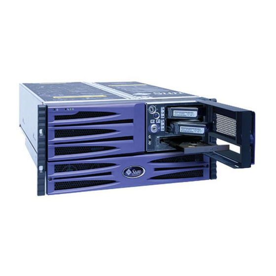
Page 85: How To Remove A Disk Drive
If a disk drive fails, the system Fault LED and the disk drive Fault LED will light. Disk drive Fault LED System Fault LED For additional information about the disk drives, see your Sun Fire V490 Server Administration Guide. You must follow antistatic precautions when handling a disk drive. Complete this task: “How to Avoid Electrostatic Discharge”... -
Page 86: What To Do
3. Pinch the disk drive latch sideways to release the disk drive handle. 4. Pull the handle away from the disk drive until you feel the disk drive connector disengage from the backplane connector. Disk drive latch Disk drive handle Sun Fire V490 Server Parts Installation and Removal Guide • October 2005... -
Page 87: How To Install A Disk Drive
Hot-Plug Operation” on page Before You Begin For additional information about internal disk drives and configuring disk drive arrays, see your Sun Fire V490 Server Administration Guide. You must follow antistatic precautions when handling a disk drive. Complete this task: “How to Avoid Electrostatic Discharge”... -
Page 88: What To Do
5. Firmly press the center of the disk drive handle toward the disk drive until the latch closes, securing the disk drive in place. What Next Complete this task: Sun Fire V490 Server Parts Installation and Removal Guide • October 2005... -
Page 89: How To Remove A Disk Drive Using The Hot-Plug Operation
Use the luxadm software tool to remove a Sun Fire V490 server’s internal disk drive using the hot-plug operation. The following procedure describes the general steps involved, but your specific device names may be different. -
Page 90: Before You Begin
You must follow antistatic precautions when handling a disk drive. Complete this task: “How to Avoid Electrostatic Discharge” on page 41 What to Do 1. Become superuser or the root user: % su Password: Sun Fire V490 Server Parts Installation and Removal Guide • October 2005... - Page 91 2. Type the following luxadm command: Where c1t1d0s2 is the logical device name for the disk drive. The system dialog follows the command. # luxadm remove_device /dev/rdsk/c1t1d0s2 WARNING!!! Please ensure that no file systems are mounted on these device(s). All data on these devices should have been backed up. The list of devices which will be removed is: 1: Device name: /dev/rdsk/c1t1d0s2 Node WWN: 20000020371b1f31...
-
Page 92: What Next
What Next If you need to install a drive using the hot-plug operation, complete this task: “How to Install a Disk Drive Using the Hot-Plug Operation” on page 63 Sun Fire V490 Server Parts Installation and Removal Guide • October 2005... -
Page 93: How To Install A Disk Drive Using The Hot-Plug Operation
Finally you configure your application (if necessary) to operate with this new drive. Use the luxadm software tool to install a Sun Fire V490 server’s internal disk drives using the hot-plug operation. The following procedure describes the general steps involved, but your specific device names may be different. -
Page 94: What To Do
1. c1t1d0 <SUN9.0G cyl 4924 alt 2 hd 27 sec 133> /pci@ 8,600000/ SUNW, qlc@ 4/ fp@ 0,0/ ssd@ w21000020371b1f31,0 Specify disk (enter its number): 1 selecting c1t1d0 [disk formatted] Sun Fire V490 Server Parts Installation and Removal Guide • October 2005... -
Page 95: What Next
4. Repeat Step 2 through Step 3 to hot-plug the other disk drive. For more information, refer to Platform Notes: Using luxadm Software, which is provided on the Solaris Software Supplement CD for the Solaris release you are running. Refer also to the luxadm(1M), devfsadm(1M), and format(1M) man pages. 5. -
Page 96: What To Do
“How to Remove the Power Supply Access Panel” on page 46 What to Do 1. Loosen the two Phillips No. 2 captive screws securing Fan Tray 0 to the front of the chassis. Fan Tray 0 mounting screws Sun Fire V490 Server Parts Installation and Removal Guide • October 2005... -
Page 97: What Next
2. Push up on the fan tray and tip it forward. Cradle the fan tray in your hand. Two mounting tabs secure Fan Tray 0 to the chassis. Fan tray mounting tabs Caution – Do not drop the fan tray. The fan tray cable is still connected to the chassis, and can be damaged if the fan tray is pulled too far away from the chassis. -
Page 98: How To Install Fan Tray 0
Insert the cable end until it clicks into place. Caution – Do not drop the fan tray. The fan tray cable can be damaged if the fan tray is pulled too far away from the chassis. Sun Fire V490 Server Parts Installation and Removal Guide • October 2005... - Page 99 3. Insert the two tabs on the fan tray frame into their corresponding slots on the front of the chassis. Chassis slots Fan tray tabs a. Be sure that the cable on the fan tray is tucked in between the fan units and the fan tray frame.
-
Page 100: What Next
Fan Tray 0 mounting screws What Next Complete these tasks: “How to Install the Power Supply Access Panel” on page 48 “How to Power On the System” on page 18 Sun Fire V490 Server Parts Installation and Removal Guide • October 2005... -
Page 101: Servicing The Cpu/Memory Board And Related Components
C H A P T E R Servicing the CPU/Memory Board and Related Components This chapter contains the following sections: “How to Remove the CPU Access Panel” on page 74 “How to Install the CPU Access Panel” on page 76 “How to Remove a CPU/Memory Board”... -
Page 102: How To Remove The Cpu Access Panel
What to Do 1. Rotate the top panel lock to the Unlocked position. The top panel lock secures both the CPU access panel and the PCI access panel. Sun Fire V490 Server Parts Installation and Removal Guide • October 2005... -
Page 103: What Next
2. Loosen the five Phillips No. 2 captive screws securing the access panel to the chassis. 3. Pull the panel straight up and off the chassis. What Next Complete this task: “How to Install the CPU Access Panel” on page 76 Chapter 4 Servicing the CPU/Memory Board and Related Components... -
Page 104: How To Install The Cpu Access Panel
2. Position the CPU access panel into its place on the chassis. Insert the four tabs along the inside edge of the CPU access panel into their corresponding slots in the chassis lip. Sun Fire V490 Server Parts Installation and Removal Guide • October 2005... -
Page 105: What Next
3. Tighten the five captive Phillips No. 2 screws that secure the access panel to the chassis. 4. Secure the top panel lock. The top panel lock secures both the CPU access panel and the PCI access panel. What Next Complete these tasks: “How to Slide the System Into the Cabinet”... -
Page 106: How To Remove A Cpu/Memory Board
“How to Remove the CPU Access Panel” on page 74 “How to Avoid Electrostatic Discharge” on page 41 Note – Use only Sun Fire V490 CPU/Memory boards in the Sun Fire V490 system. What to Do 1. Identify the CPU/Memory board to be removed. - Page 107 2. Loosen the two Phillips No. 2 captive screws securing the CPU/Memory board to the chassis. 3. Rotate the CPU/Memory board ejector levers outward so that the CPU/Memory board connectors disengage from the centerplane. 4. Pull the CPU/Memory board from the chassis and place it on an antistatic mat. Chapter 4 Servicing the CPU/Memory Board and Related Components...
-
Page 108: What Next
CPU/Memory board connectors. See “Centerplane Connectors” on page 215 for the connector location. What Next Complete this task: “How to Install a CPU/Memory Board” on page 81 Sun Fire V490 Server Parts Installation and Removal Guide • October 2005... -
Page 109: How To Install A Cpu/Memory Board
“How to Remove a Memory Module” on page 87 “How to Install a Memory Module” on page 91 Note – Use only Sun Fire V490 CPU/Memory boards in the Sun Fire V490 system. What to Do 1. Locate the CPU/Memory board slot into which you want to install the CPU/Memory board. - Page 110 5. Push in the two ejector levers until they are completely pressed into their slots. 6. Hand-tighten the two captive screws on the CPU/Memory board. Sun Fire V490 Server Parts Installation and Removal Guide • October 2005...
-
Page 111: What Next
7. Using a Phillips No. 2 screwdriver, tighten the right-side captive screw (close to the front of the system). 8. Using a Phillips No. 2 screwdriver, tighten the left-side captive screw (close to the back of the system). What Next Complete these tasks: “How to Install the CPU Access Panel”... -
Page 112: About Memory Modules
About Memory Modules The Sun Fire V490 server uses 3.3V, high-capacity dual inline memory modules (DIMMs). The DIMMs are built with synchronous dynamic random access memory (SDRAM) chips that operate at a 75-MHz clock frequency. Each CPU/Memory board contains slots for 16 DIMMs. Within each CPU/Memory board, the 16 DIMM slots are organized into groups of four. - Page 113 The figure below shows the DIMM slots and DIMM groups on a CPU/Memory board. Every fourth slot belongs to the same DIMM group. The four groups are designated A0, A1, B0, and B1. Follow these configuration rules when installing memory: DIMMs must be added four at a time within the same group of DIMM slots;...
-
Page 114: Dimm Installation Guidelines
For additional information about DIMMs, refer to your Sun Fire V490 Server Administration Guide. Sun Fire V490 Server Parts Installation and Removal Guide • October 2005... -
Page 115: How To Remove A Memory Module
How to Remove a Memory Module Before You Begin Read the section: “About Memory Modules” on page 84 Complete these tasks: “How to Power Off the System” on page 22 “How to Slide the System Out of the Cabinet” on page 25 “How to Remove the CPU Access Panel”... - Page 116 2. Identify the memory module to be removed. 3. Push down on the ejector levers on each end of the memory module until it pops out of its connector. Apply even pressure on both levers. Sun Fire V490 Server Parts Installation and Removal Guide • October 2005...
- Page 117 4. Grasp the top corners of the memory module and pull it up and out of its connector. 5. Place the memory module on an antistatic mat. 6. Repeat Step 2 through Step 5 for all the DIMMs to be removed. Chapter 4 Servicing the CPU/Memory Board and Related Components...
-
Page 118: What Next
To fully engage the tabs on the access panel, push them in until you hear a click. What Next To replace a memory module, complete this task: “How to Install a Memory Module” on page 91 Sun Fire V490 Server Parts Installation and Removal Guide • October 2005... -
Page 119: How To Install A Memory Module
How to Install a Memory Module Before You Begin Read the section: “About Memory Modules” on page 84 Complete these tasks: “How to Power Off the System” on page 22 “How to Slide the System Out of the Cabinet” on page 25 “How to Remove the CPU Access Panel”... - Page 120 Push both tabs inward until you can lift the access panel free of the CPU/Memory board shroud. 2. Locate the slot into which you will install the memory module. 3. Rotate out the memory module ejector levers for that slot. Sun Fire V490 Server Parts Installation and Removal Guide • October 2005...
- Page 121 4. Holding the bottom edge of the module parallel to its slot, carefully align the module so that each of its contacts is centered on a connector pin. Be sure the DIMM is correctly oriented. A notch along the bottom of the DIMM corresponds to a tab on the connector.
-
Page 122: What Next
“How to Install the CPU Access Panel” on page 76 “How to Slide the System Into the Cabinet” on page 31 “How to Power On the System” on page 18 Sun Fire V490 Server Parts Installation and Removal Guide • October 2005... -
Page 123: Servicing The Pci Riser Board And Related Components
C H A P T E R Servicing the PCI Riser Board and Related Components This chapter contains the following sections: “How to Remove the PCI Access Panel” on page 100 “How to Install the PCI Access Panel” on page 102 “How to Remove Fan Tray 1”... -
Page 124: How To Remove The Pci Access Panel
What to Do 1. Rotate the top panel lock to the Unlocked position. The top panel lock secures both the CPU access panel and the PCI access panel. Sun Fire V490 Server Parts Installation and Removal Guide • October 2005... -
Page 125: What Next
2. Loosen the three Phillips No. 2 captive screws securing the access panel to the chassis. 3. Pull the panel up and off the chassis. Pull the access panel up from the left-side edge. What Next Complete this task: “How to Install the PCI Access Panel” on page 102 Chapter 5 Servicing the PCI Riser Board and Related Components... -
Page 126: How To Install The Pci Access Panel
Align the lip on the right side of the access panel with the corresponding ridge on the chassis. 3. Tighten the three Phillips No. 2 captive screws that secure the access panel to the chassis. Sun Fire V490 Server Parts Installation and Removal Guide • October 2005... -
Page 127: What Next
4. Secure the top panel lock. The top panel lock secures both the CPU access panel and the PCI access panel. What Next Complete these tasks: “How to Slide the System Into the Cabinet” on page 31 “How to Power On the System” on page 18 How to Remove Fan Tray 1 Caution –... -
Page 128: What To Do
What to Do Caution – Fan Tray 1 does not include fan guards. Serious injury can result if you attempt to remove it while the system is running. Sun Fire V490 Server Parts Installation and Removal Guide • October 2005... -
Page 129: What Next
Pull the fan tray straight up and out of its bracket on the PCI riser board, and set it aside. What Next Complete this task: “How to Install Fan Tray 1” on page 105 How to Install Fan Tray 1 Caution –... -
Page 130: What To Do
“How to Install the PCI Access Panel” on page 102 “How to Slide the System Into the Cabinet” on page 31 “How to Power On the System” on page 18 Sun Fire V490 Server Parts Installation and Removal Guide • October 2005... -
Page 131: How To Remove The System Controller (Sc) Card
How to Remove the System Controller (SC) Card Before You Begin Complete these tasks: “How to Power Off the System” on page 22 “How to Slide the System Out of the Cabinet” on page 25 “How to Remove the PCI Access Panel” on page 100 “How to Avoid Electrostatic Discharge”... - Page 132 3. Disconnect any external cables attached to the faceplate of the SC card. Note and label cable connector locations. 4. Using a Phillips No. 1 screwdriver, remove the screw securing the card to the chassis back panel. Sun Fire V490 Server Parts Installation and Removal Guide • October 2005...
-
Page 133: What Next
Caution – Be sure that the AC power cords are disconnected from the system before removing the SC card. 5. Pull the SC card from its slot on the PCI riser board. Caution – Do not apply excessive force to one end or one side of the card. Doing so could damage the card. -
Page 134: What To Do
2. Insert the SC card into its slot on the PCI riser board. a. Insert the faceplate end of the card into the appropriate opening in the back panel. Sun Fire V490 Server Parts Installation and Removal Guide • October 2005... -
Page 135: What Next
b. Insert the opposite end of the card into the appropriate card guide so that the card is aligned evenly with the connectors on the PCI riser board. c. Push the card into the connectors on the PCI riser board. Apply even pressure along the edge of the card. -
Page 136: How To Remove A Pci Card
What to Do 1. Disconnect any external cables attached to the faceplate of the PCI card. 2. Disconnect any cables connected to the internal connectors on the PCI card. Sun Fire V490 Server Parts Installation and Removal Guide • October 2005... - Page 137 3. Using a Phillips No. 1 screwdriver, remove the screw securing the card to the chassis back panel. 4. Pull the PCI card from its slot. Caution – Do not apply excessive force to one end or one side of the card. Doing so could damage the card.
-
Page 138: What Next
“How to Slide the System Into the Cabinet” on page 31 “How to Power On the System” on page 18 “How to Initiate a Reconfiguration Boot” on page 23 Sun Fire V490 Server Parts Installation and Removal Guide • October 2005... -
Page 139: How To Install A Pci Card
How to Install a PCI Card Before You Begin Complete these tasks: “How to Power Off the System” on page 22 “How to Slide the System Out of the Cabinet” on page 25 “How to Remove the PCI Access Panel” on page 100 “How to Avoid Electrostatic Discharge”... - Page 140 Insert the faceplate end of the card into the appropriate opening in the back panel. If you are installing a PCI long card, guide the opposite end of the PCI card into the corresponding card runner on the PCI riser board. Sun Fire V490 Server Parts Installation and Removal Guide • October 2005...
- Page 141 b. Push the card into the corresponding connector on the PCI riser board. Caution – Do not apply excessive force to one end or one side of the card. Doing so could damage the card. Apply even pressure along the edge of the card. 4.
-
Page 142: What Next
“How to Avoid Electrostatic Discharge” on page 41 Read the documentation supplied with the Sun StorEdge PCI Dual Fibre-Channel Host Adapter for information about jumper settings, PCI slot requirements, and cable connections. Sun Fire V490 Server Parts Installation and Removal Guide • October 2005... -
Page 143: What To Do
What to Do 1. Locate an unused 66-MHz PCI slot, either slot 0 or slot 1. 66-MHz PCI slots 2. If you are installing the Sun StorEdge PCI Dual Fibre-Channel Host Adapter into an unused slot, remove the corresponding filler panel from the chassis back panel. Otherwise go to Step a. - Page 144 Apply even pressure along the edge of the card. 4. Using a Phillips No. 1 screwdriver, secure the card faceplate to the back panel. Sun Fire V490 Server Parts Installation and Removal Guide • October 2005...
-
Page 145: Cable Connections And Routing
Channel Host Adapter’s internal connectors and the FC-AL backplane. The Loop B cable assembly is purchased separately from the Sun StorEdge PCI Dual Fibre-Channel Host Adapter, and is unique to the Sun Fire V490 server. See “System Cables” on page 226 for the correct part number. -
Page 146: What Next
“How to Slide the System Into the Cabinet” on page 31 “How to Power On the System” on page 18 “How to Initiate a Reconfiguration Boot” on page 23 Sun Fire V490 Server Parts Installation and Removal Guide • October 2005... -
Page 147: How To Remove The Pci Riser Board
How to Remove the PCI Riser Board Before You Begin Depopulate the PCI riser board by completing the following tasks: “How to Power Off the System” on page 22 “How to Slide the System Out of the Cabinet” on page 25 “How to Remove the PCI Access Panel”... -
Page 148: What To Do
Press the tab to release the cable end from its connector. c. Disconnect the removable media assembly (RMA) data cable from J1001. Pull up the ejector levers until the cable end comes off the connector. Sun Fire V490 Server Parts Installation and Removal Guide • October 2005... -
Page 149: What Next
d. Disconnect the Fan Tray 0 power cable from J2302. Press the tab to release the cable end from its connector. 4. Remove the two Phillips No. 2 screws securing the PCI riser board to its mounting bracket. 5. Rotate the mounting levers outward to release the PCI riser board from the chassis. -
Page 150: How To Install The Pci Riser Board
Note – Be sure to keep all the cables clear of the left side of the PCI riser board as you insert it into the system. Sun Fire V490 Server Parts Installation and Removal Guide • October 2005... - Page 151 2. Push the mounting levers inward to seat the PCI riser board connectors into their corresponding connectors on the centerplane. 3. Using a Phillips No. 2 screwdriver, replace the two screws that secure the PCI riser board to the chassis. 4.
-
Page 152: What Next
“How to Power On the System” on page 18 Caution – Do not reconnect the AC power cords to the back of the system until after you have installed the SC card. Sun Fire V490 Server Parts Installation and Removal Guide • October 2005... -
Page 153: How To Remove The Idprom Module
How to Remove the IDPROM Module This section explains how to remove a functioning ID programable read-only memory (IDPROM) module so that you can install it on a new PCI riser board, thereby preserving the system’s host ID information. If you are replacing a defective IDPROM module and want to retain the same host ID, consult your authorized Sun sales representative or service provider for assistance with programming the new IDPROM module with the existing host ID and Ethernet address. -
Page 154: How To Install The Idprom Module
IDPROM module in order to preserve your system’s host ID and Ethernet address. Before You Begin Complete this task: “How to Remove the IDPROM Module” on page 129 Sun Fire V490 Server Parts Installation and Removal Guide • October 2005... -
Page 155: What Next
What to Do 1. Insert the IDPROM module into its socket on the PCI riser board. Make sure that the notch on the IDPROM module is on the same side as the notch on the connector on the PCI riser board. IDPROM module Matching... - Page 156 Sun Fire V490 Server Parts Installation and Removal Guide • October 2005...
-
Page 157: Servicing Miscellaneous Components
C H A P T E R Servicing Miscellaneous Components This chapter contains the following sections: “How to Remove the FC-AL Backplane” on page 134 “How to Install the FC-AL Backplane” on page 136 “How to Remove the Removable Media Assembly” on page 137 “How to Install the Removable Media Assembly”... -
Page 158: How To Remove The Fc-Al Backplane
2. Disconnect the FC-AL data cable from J0200 on the FC-AL backplane. Push the ejector levers apart to eject the cable from its connector. 3. Loosen the two Phillips No. 1 captive screws on the FC-AL backplane mounting bracket. Sun Fire V490 Server Parts Installation and Removal Guide • October 2005... -
Page 159: What Next
4. Pull the FC-AL backplane straight up, off its mounting tabs. 5. Set the FC-AL backplane aside on an antistatic mat. What Next Complete this task: “How to Install the FC-AL Backplane” on page 136 Chapter 6 Servicing Miscellaneous Components... -
Page 160: How To Install The Fc-Al Backplane
Push the FC-AL backplane straight down until it locks into place. Make sure that the slot in the FC-AL backplane and mounting bracket mate with the corresponding tabs on the chassis drive bay. Sun Fire V490 Server Parts Installation and Removal Guide • October 2005... -
Page 161: What Next
2. Tighten the two Phillips No. 1 captive screws on the mounting bracket. 3. Connect the FC-AL power cable to the FC-AL backplane at J0201. Push in the cable until it snaps into place. 4. Connect the FC-AL data cable to the FC-AL backplane at J0200. Push in the cable until the ejector levers snap into place. -
Page 162: What Next
DVD-ROM drive from the RMA bracket. What Next If you are replacing a failed DVD-ROM drive or failed RMA cable, see: “How to Remove the Removable Media Assembly Cable” on page 173 Sun Fire V490 Server Parts Installation and Removal Guide • October 2005... -
Page 163: How To Install The Removable Media Assembly
Complete this task: “How to Install the Removable Media Assembly” on page 139 How to Install the Removable Media Assembly Before You Begin Complete this task: “How to Remove the Removable Media Assembly” on page 137 What to Do 1. Thread the removable media assembly (RMA) cable through the RMA bay. Chapter 6 Servicing Miscellaneous Components... -
Page 164: What Next
“How to Install the PCI Access Panel” on page 102 “How to Slide the System Into the Cabinet” on page 31 “How to Power On the System” on page 18 Sun Fire V490 Server Parts Installation and Removal Guide • October 2005... -
Page 165: How To Remove The Dvd-Rom Drive
How to Remove the DVD-ROM Drive Before You Begin Complete these tasks: “How to Power Off the System” on page 22 “How to Slide the System Out of the Cabinet” on page 25 “How to Remove the PCI Access Panel” on page 100 “How to Avoid Electrostatic Discharge”... -
Page 166: What Next
1. Slide the DVD-ROM drive onto the removable media assembly (RMA) bracket. 2. Using a Phillips No. 1 screwdriver, attach the DVD-ROM drive to the RMA bracket. The DVD-ROM drive is secured with four mounting screws. Sun Fire V490 Server Parts Installation and Removal Guide • October 2005... -
Page 167: What Next
What Next Complete these tasks: “How to Install the Removable Media Assembly Cable” on page 174 “How to Install the Removable Media Assembly” on page 139 “How to Install Fan Tray 1” on page 105 “How to Install the PCI Access Panel” on page 102 “How to Slide the System Into the Cabinet”... -
Page 168: How To Remove The Centerplane
Caution – If you are using an antistatic wrist strap to protect against electrostatic discharge, connect it to a properly grounded surface, such as a nearby equipment rack, or a nearby system that is connected to a power source. Sun Fire V490 Server Parts Installation and Removal Guide • October 2005... -
Page 169: What To Do
What to Do Caution – If you are using an antistatic wrist strap to protect against electrostatic discharge, connect it to a properly grounded surface, such as a nearby equipment rack, or a nearby system that is connected to a power source. 1. -
Page 170: What Next
Be careful not to damage the connectors securing the centerplane to the power distribution board. What Next Complete this task: “How to Install the Centerplane” on page 147 Sun Fire V490 Server Parts Installation and Removal Guide • October 2005... -
Page 171: How To Install The Centerplane
How to Install the Centerplane It is mechanically feasible to service the centerplane with the system installed in the cabinet. However, it is easier to remove the system from the cabinet and perform this procedure on a workbench. To remove the system from the cabinet, see “How to Remove the System From the Cabinet”... - Page 172 5. Using a Phillips No. 2 screwdriver, install the screw that secures the centerplane top stiffener to the front of the system. Sun Fire V490 Server Parts Installation and Removal Guide • October 2005...
-
Page 173: What Next
6. Using a Phillips No. 2 screwdriver, install the external connector faceplate on the back panel. The faceplate is fastened with seven Phillips screws. 7. Connect the AC power cords to the back of the system. What Next Complete these tasks: “How to Install a CPU/Memory Board”... -
Page 174: How To Remove The Power Distribution Board
Note – If your system is equipped with two CPU/Memory boards, you must remove both of them from the system. Note – Use only the Sun Fire V490 200-240 VAC power distribution board in the Sun Fire V490 system. Sun Fire V490 Server Parts Installation and Removal Guide • October 2005... -
Page 175: What To Do
Caution – If you are using an antistatic wrist strap to protect against electrostatic discharge, connect it to a properly grounded surface, such as a nearby equipment rack, or a nearby system that is connected to a power source. What to Do Caution –... - Page 176 Caution – Be careful not to damage the light pipes mounted to the rear of the power distribution board. 5. Place the power distribution board on an antistatic mat. Sun Fire V490 Server Parts Installation and Removal Guide • October 2005...
-
Page 177: What Next
Complete this task: “How to Remove the Power Distribution Board” on page 150 Note – Use only the Sun Fire V490 200-240 VAC power distribution board in the Sun Fire V490 system. Caution – If you are using an antistatic wrist strap to protect against electrostatic discharge, connect it to a properly grounded surface, such as a nearby equipment rack, or a nearby system that is connected to a power source. -
Page 178: What To Do
Caution – Be careful not to damage the light pipes mounted to the rear of the power distribution board. 2. Slide the power distribution board back under the two rear corner screws. Sun Fire V490 Server Parts Installation and Removal Guide • October 2005... - Page 179 3. Using a long-stem Phillips No. 2 screwdriver, replace the first four screws that secure the power distribution board to the chassis. Replace the left-front screw first, then replace the remaining screws. 4. Tighten the remaining two screws. Chapter 6 Servicing Miscellaneous Components...
-
Page 180: What Next
“How to Remove Fan Tray 1” on page 103 “How to Remove the FC-AL Backplane” on page 134 “How to Remove the Removable Media Assembly” on page 137 Sun Fire V490 Server Parts Installation and Removal Guide • October 2005... -
Page 181: What To Do
What to Do 1. Disconnect the system control switch/power button cable from J1401 on the PCI riser board. Pull the system control switch/power button cable end out from behind the centerplane-side Fan Tray 1 mounting bracket. 2. Disconnect the Fan Tray 0 power cable from J2302 on the PCI riser board. Pull the cable out from behind the centerplane-side Fan Tray 1 mounting bracket. - Page 182 Caution – Do not drop the media door assembly. The system control switch/power button cable is attached to the media door assembly, and it can be damaged if the media door assembly is pulled too far away from the chassis. Sun Fire V490 Server Parts Installation and Removal Guide • October 2005...
-
Page 183: What Next
6. Remove the system control switch/power button cable mounting plate from the media door assembly. The mounting plate is secured with two Phillips No. 2 screws. What Next Complete this task: “How to Install the Media Door Assembly” on page 160 Chapter 6 Servicing Miscellaneous Components... -
Page 184: How To Install The Media Door Assembly
2. With your other hand, attach the system control switch/power button cable mounting plate to the media door assembly. Secure the mounting plate with two Phillips No. 2 screws. Sun Fire V490 Server Parts Installation and Removal Guide • October 2005... - Page 185 Caution – Do not drop the media door assembly. The system control switch/power button cable can be damaged if the media door assembly is pulled too far away from the chassis. Chapter 6 Servicing Miscellaneous Components...
- Page 186 Be sure that the system control switch/power button cable is routed cleanly back through the chassis, beside the drive bay. 4. Replace the two Phillips No. 1 screws that secure the media door assembly to the chassis. Mounting screws Sun Fire V490 Server Parts Installation and Removal Guide • October 2005...
-
Page 187: What Next
5. Route the Fan Tray 0 cable behind the faceplate, and connect it to J2302 on the PCI riser board. Press the cable end into its socket until it snaps into place. 6. Route the system control switch/power button cable behind the centerplane-side Fan Tray 1 bracket, and connect it to J1401 on the PCI riser board. - Page 188 Sun Fire V490 Server Parts Installation and Removal Guide • October 2005...
-
Page 189: Servicing Cables
C H A P T E R Servicing Cables This chapter contains the following sections: “Cable Connections and Routing” on page 166 “How to Remove the FC-AL Power Cable” on page 168 “How to Install the FC-AL Power Cable” on page 169 “How to Remove the FC-AL Data Cable”... -
Page 190: Cable Connections And Routing
Connect the P2 cable end (RMA) cable (P1) first; route under the drive bay; tuck any excess cable (F375-3053) length under the PCI riser board before installing the RMA. Sun Fire V490 Server Parts Installation and Removal Guide • October 2005... - Page 191 Cable Connections and Routing (Continued) TABLE 7-1 Cable Name and Part Number Routed From Routed To Cable Management Notes System control PCI riser board at J1401 Media door Route between the drive switch/power button cable (P1) bay and the centerplane; (F540-5063) attach the P2 cable end (using the system control...
-
Page 192: How To Remove The Fc-Al Power Cable
1. Disconnect the FC-AL power cable end at J0201 on the FC-AL backplane. Press the locking tab on the cable end and pull it off its connector. FC-AL power cable Sun Fire V490 Server Parts Installation and Removal Guide • October 2005... -
Page 193: What Next
2. Disconnect the FC-AL power cable end at J1901 on the PCI riser board. Press the locking tab on the cable end and pull it off its connector. What Next Complete this task: “How to Install the FC-AL Power Cable” on page 169 How to Install the FC-AL Power Cable Before You Begin Complete this task:... -
Page 194: How To Remove The Fc-Al Data Cable
“How to Slide the System Into the Cabinet” on page 31 “How to Power On the System” on page 18 How to Remove the FC-AL Data Cable Before You Begin Complete these tasks: Sun Fire V490 Server Parts Installation and Removal Guide • October 2005... -
Page 195: What Next
“How to Power Off the System” on page 22 “How to Slide the System Out of the Cabinet” on page 25 “How to Avoid Electrostatic Discharge” on page 41 “How to Remove the PCI Access Panel” on page 100 What to Do 1. -
Page 196: How To Install The Fc-Al Data Cable
Push the cable end into its connector until the ejector levers snap into place. FC-AL data cable 3. Connect the P2 cable end to J6502 on the centerplane. Sun Fire V490 Server Parts Installation and Removal Guide • October 2005... -
Page 197: What Next
What Next Complete these tasks: “How to Install the PCI Access Panel” on page 102 “How to Slide the System Into the Cabinet” on page 31 “How to Power On the System” on page 18 How to Remove the Removable Media Assembly Cable Before You Begin Complete these tasks:... -
Page 198: What To Do
“How to Install the Removable Media Assembly Cable” on page 174 How to Install the Removable Media Assembly Cable Before You Begin Complete this task: “How to Remove the Removable Media Assembly Cable” on page 173 Sun Fire V490 Server Parts Installation and Removal Guide • October 2005... -
Page 199: What To Do
What to Do 1. Connect the removable media assembly (RMA) cable end to its corresponding connector on the DVD-ROM drive. 2. Using a Phillips No. 1 screwdriver, attach the three screws that secure the RMA cable to the DVD-ROM drive. What Next Complete these tasks: “How to Install the Removable Media Assembly”... -
Page 200: How To Remove The System Control Switch/Power Button Cable
1. Disconnect the P3 cable end from the back panel flex-circuit cable. Press the tab to unlock the cable end. Unhook the cable from its clips on the chassis. Sun Fire V490 Server Parts Installation and Removal Guide • October 2005... -
Page 201: How To Install The System Control Switch/Power Button Cable
2. Remove the cable from the cable tie on the side of the drive bay. 3. Pull the cable up and out of the chassis. What Next Complete this task: “How to Install the System Control Switch/Power Button Cable” on page 177 How to Install the System Control Switch/Power Button Cable Before You Begin... -
Page 202: What Next
“How to Install the Power Supply Access Panel” on page 48 “How to Install the System Into the Cabinet” on page 36 “How to Power On the System” on page 18 Sun Fire V490 Server Parts Installation and Removal Guide • October 2005... -
Page 203: How To Remove The Back Panel Led Flex Circuit
How to Remove the Back Panel LED Flex Circuit Before You Begin Note – If you remove the back panel LED flex circuit, you must replace it with a new one. Complete these tasks: “How to Power Off the System” on page 22 “How to Slide the System Out of the Cabinet”... -
Page 204: What Next
3. Peel off the back panel LED flex circuit from the back panel. Back panel LED flex circuit What Next “How to Install the Back Panel LED Flex Circuit” on page 181 Sun Fire V490 Server Parts Installation and Removal Guide • October 2005... -
Page 205: How To Install The Back Panel Led Flex Circuit
How to Install the Back Panel LED Flex Circuit Before You Begin Complete this task: “How to Remove the Back Panel LED Flex Circuit” on page 179 What to Do 1. Peel off the backing paper from the new back panel LED flex circuit. 2. -
Page 206: What Next
How to Remove the Fan Tray 0 Cable Before You Begin Complete these tasks: “How to Power Off the System” on page 22 “How to Slide the System Out of the Cabinet” on page 25 Sun Fire V490 Server Parts Installation and Removal Guide • October 2005... -
Page 207: What To Do
“How to Avoid Electrostatic Discharge” on page 41 “How to Remove the Power Supply Access Panel” on page 46 “How to Remove Fan Tray 0” on page 65 “How to Remove the PCI Access Panel” on page 100 “How to Remove Fan Tray 1” on page 103 What to Do 1. -
Page 208: How To Install The Fan Tray 0 Cable
3. Connect the P1 cable end to J2302 on the PCI riser board. 4. Using a Phillips No. 2 screwdriver, attach the Fan Tray 0 cable mounting bracket to the front of the chassis. Sun Fire V490 Server Parts Installation and Removal Guide • October 2005... -
Page 209: What Next
What Next Complete these tasks: “How to Install Fan Tray 1” on page 105 “How to Install the PCI Access Panel” on page 102 “How to Install Fan Tray 0” on page 68 “How to Install the Power Supply Access Panel” on page 48 “How to Slide the System Into the Cabinet”... - Page 210 Sun Fire V490 Server Parts Installation and Removal Guide • October 2005...
-
Page 211: 2-Post Rack Service Requirements
A P P E N D I X 2-Post Rack Service Requirements This appendix describes service requirements for systems installed in a 2-post rack. It contains the following sections: “Servicing a System Installed in a 2-Post Rack” on page 188 “How to Remove the System From an Empty 2-Post Rack”... -
Page 212: Servicing A System Installed In A 2-Post Rack
Miscellaneous components—See Chapter FC-AL backplane Removable media assembly (RMA) Centerplane Power distribution board Cables—See Chapter FC-AL power cable FC-AL data cable RMA data cable System control switch/power button cable Sun Fire V490 Server Parts Installation and Removal Guide • October 2005... -
Page 213: How To Remove The System From An Empty 2-Post Rack
How to Remove the System From an Empty 2-Post Rack Before You Begin Complete this task: “How to Power Off the System” on page 22 Caution – The chassis is heavy. Two persons are required to remove the system from the rack in the following procedure. What to Do 1. -
Page 214: What Next
5. Pull the server out of the rack. What Next Complete this task: “How to Install the System Into an Empty 2-Post Rack” on page 191 Sun Fire V490 Server Parts Installation and Removal Guide • October 2005... -
Page 215: How To Install The System Into An Empty 2-Post Rack
How to Install the System Into an Empty 2-Post Rack Before You Begin Complete the following task: “How to Remove the System From an Empty 2-Post Rack” on page 189 Caution – The chassis is heavy. Two persons are required to install the system into the rack in the following procedure. - Page 216 4. Connect all external cables that were attached to the back panel of the system. Examine each disconnected cable for information indicating the cable’s origin and its terminating connection. Sun Fire V490 Server Parts Installation and Removal Guide • October 2005...
-
Page 217: What Next
What Next Complete this task: “How to Power On the System” on page 18 If you have added or removed a PCI card, CPU/Memory board, or DIMMs, complete this task: “How to Initiate a Reconfiguration Boot” on page 23 How to Remove the System From a Populated 2-Post Rack Before You Begin Complete the following task:... -
Page 218: What To Do
Caution – When removing the server from a populated 2-post rack, be sure to support the weight of the server, so you do not damage the component installed below it in the rack. Sun Fire V490 Server Parts Installation and Removal Guide • October 2005... -
Page 219: What Next
3. Slide the server out of the rack. What Next Complete this task: “How to Install the System Into a Populated 2-Post Rack” on page 196 Appendix A 2-Post Rack Service Requirements... -
Page 220: How To Install The System Into A Populated 2-Post Rack
Caution – The chassis is heavy. Two persons are required to install the system into the rack in the following procedure. What to Do 1. Slide the server into the open position in the rack. Sun Fire V490 Server Parts Installation and Removal Guide • October 2005... - Page 221 2. Using a Phillips No. 2 screwdriver, secure the top and bottom screws to the left and the right vertical mounting rails. Use M5 screws for a Metric rack and 10-32 screws for an English rack. Appendix A 2-Post Rack Service Requirements...
- Page 222 “How to Power On the System” on page 18 If you have added or removed a PCI card, CPU/Memory board, or DIMMs, complete this task: “How to Initiate a Reconfiguration Boot” on page 23 Sun Fire V490 Server Parts Installation and Removal Guide • October 2005...
-
Page 223: Connector Pinouts
A P P E N D I X Connector Pinouts This appendix gives you reference information about the system’s back panel ports and pin assignments. Topics covered in this appendix include: “Serial Port Connector” on page 200 “USB Connector” on page 201 “Twisted-Pair Ethernet Connector”... -
Page 224: Serial Port Connector Signals
Serial Port Connector Signals TABLE B-1 Signal Description Signal Description Request To Send Ground Data Terminal Ready Receive Data Transmit Data Data Set Ready Ground Clear To Send Sun Fire V490 Server Parts Installation and Removal Guide • October 2005... -
Page 225: Usb Connector Signals
USB Connector Two Universal Serial Bus (USB) connectors are located on the centerplane and can be accessed from the back panel. USB Connector Diagram USB Connector Signals USB Connector Signals TABLE B-2 Signal Description Signal Description +5 VDC +5 VDC Port Data0 –... -
Page 226: Tpe Connector Signals
Signal Description Signal Description Transmit/Receive Data0 + Transmit/Receive Data2 – Transmit/Receive Data0 – Transmit/Receive Data1 – Transmit/Receive Data1 + Transmit/Receive Data3 + Transmit/Receive Data2 + Transmit/Receive Data3 – Sun Fire V490 Server Parts Installation and Removal Guide • October 2005... -
Page 227: Sc Ethernet Connector Signals
SC Ethernet Connector The system controller (SC) Ethernet connector is an RJ-45 connector located on the SC card and can be accessed from the back panel. SC Ethernet Connector Diagram SC Ethernet Connector Signals SC Ethernet Connector Signals TABLE B-4 Signal Description Signal Description Transmit/Receive Data0 +... -
Page 228: Sc Serial Connector Signals
SC Serial Connector Signals TABLE B-5 Signal Description Signal Description Request To Send Ground Data Terminal Ready Receive Data Transmit Data Data Set Ready Ground Clear To Send Sun Fire V490 Server Parts Installation and Removal Guide • October 2005... -
Page 229: Hssdc Connector Signals
FC-AL Port HSSDC Connector The Fibre Channel-Arbitrated Loop port high-speed serial data connector (HSSDC) is located on the centerplane and can be accessed from the back panel. HSSDC Connector Diagram HSSDC Connector Signals HSSDC Connector Signals TABLE B-6 Signal Description Signal Description Differential Data Output + Optical Output Disable... - Page 230 Sun Fire V490 Server Parts Installation and Removal Guide • October 2005...
-
Page 231: Physical Specifications
A P P E N D I X System Specifications This appendix provides the following specifications for the Sun Fire V490 server: “Physical Specifications” on page 207 “Electrical Specifications” on page 208 “Environmental Specifications” on page 209 “Agency Compliance Specifications” on page 210 “Clearance and Service Access Specifications”... -
Page 232: Electrical Specifications
50 or 60 Hz Nominal Voltage Range Auto ranging 200–240 VAC Maximum Current AC RMS 8A @ 200-240 VAC Maximum AC Power Consumption 1600 W Maximum Heat Dissipation 5459 BTU/hr Sun Fire V490 Server Parts Installation and Removal Guide • October 2005... -
Page 233: Environmental Specifications
Environmental Specifications The operating and non-operating environmental specifications for the system are described in TABLE C-3 Environmental Specifications TABLE C-3 Parameter Value Operating Temperature 5˚C to 35˚C (41˚F to 95˚F)—IEC 60068-2-1&2 Humidity 20% to 80% RH noncondensing; 27˚C (81˚F) wet bulb— IEC 60068-2-3&56 Altitude 0 to 3000 meters (0 to 10,000 feet)—IEC 60068-2-13... -
Page 234: Agency Compliance Specifications
47 CFR 15B Class A EN55022 Class A VCCI Class A ICES-003 AS/NZ 3548 CNS 13438 Immunity EN55024 IEC 61000-4-2 IEC 61000-4-3 IEC 61000-4-4 IEC 61000-4-5 IEC 61000-4-6 IEC 61000-4-8 IEC 61000-4-11 Sun Fire V490 Server Parts Installation and Removal Guide • October 2005... -
Page 235: Clearance And Service Access Specifications
Clearance and Service Access Specifications Minimum clearances needed for servicing the system are described in TABLE C-5 Clearance and Service Access Specifications TABLE C-5 Blockage Required Clearance Front Blockage Only 36 in (92 cm) Rear Blockage Only 36 in (92 cm) Front and Rear Blockage 36 in (92 cm) Front Clearance... - Page 236 Sun Fire V490 Server Parts Installation and Removal Guide • October 2005...
- Page 237 A P P E N D I X Board Connector Locations This appendix illustrates the connector locations on the system boards. It contains the following sections: “PCI Riser Board Connectors” on page 214 “FC-AL Backplane Connectors” on page 214 “Centerplane Connectors” on page 215 “SC Card Connectors”...
-
Page 238: Pci Riser Board Connectors
(FC-AL Loop B cable, to Sun StorEdge PCI Dual Fibre-Channel Host Adapter) J0203 (FC-AL Loop B cable, from Sun StorEdge PCI Dual Fibre-Channel Host Adapter) J0201 J0200 (FC-AL data cable) (FC-AL power cable) Sun Fire V490 Server Parts Installation and Removal Guide • October 2005... -
Page 239: Centerplane Connectors
Centerplane Connectors PCI Riser Board-Side Connectors J6502 (FC-AL data connector) USB ports Ethernet ports PCI riser board connector Serial port FC-AL port Appendix D Board Connector Locations... -
Page 240: Cpu/Memory Board-Side Connectors
CPU/Memory Board-Side Connectors CPU/Memory board A connector CPU/Memory board B connector Sun Fire V490 Server Parts Installation and Removal Guide • October 2005... -
Page 241: Sc Card Connectors
SC Card Connectors Serial connector Ethernet connector Appendix D Board Connector Locations... - Page 242 Sun Fire V490 Server Parts Installation and Removal Guide • October 2005...
-
Page 243: Cpu-Side Components
A P P E N D I X Illustrated Parts Breakdown This appendix consists of a sequence of illustrations that show how the various pieces of the system fit together. Use the accompanying tables as a reference for ordering field-replaceable units (FRUs). The part numbers listed in the following tables are correct as of the manual publication date but are subject to change without notice. -
Page 244: Table E-1 Chassis Doors And Access Panels
PCI access panel 540-4714 (Not a FRU) PCI riser board access panel 540-4712 (Not a FRU) Media door 540-4907 (Not a FRU) Power supply access panel 540-4765 (Not a FRU) Sun Fire V490 Server Parts Installation and Removal Guide • October 2005... -
Page 245: Cpu-Side Components
CPU-Side Components CPU-Side Components TABLE E-2 Reference Number Part Part Number CPU access panel 540-4713 (Not a FRU) 1.05-GHz CPU/Memory board F501-6809 1.35-GHz CPU/Memory board F501-6962 (not shown) 1.5-GHz CPU/Memory board F501-7058 (not shown) DIMM access panel (Shipped with CPU/Memory boards) 512 MB DIMM F501-5030 1 GB DIMM (not shown) - Page 246 Sun Fire V490 Server Parts Installation and Removal Guide • October 2005...
-
Page 247: Pci-Side Components
PCI-Side Components PCI-Side Components TABLE E-3 Reference Number Part Part Number PCI access panel 540-4714 (Not a FRU) System controller (SC) card F501-6767 IDPROM (Shipped with F501-5820) PCI riser board access panel 540-4712 (Not a FRU) PCI riser board F501-5820 FC-AL backplane F501-5822 Fan Tray 1... -
Page 248: Front Panel Components
540-4907 (Not a FRU) RMA bezel (Not a FRU) Power supply access panel 540-4765 (Not a FRU) Power supply F300-1632 Decorative panel 330-3277 (Not a FRU) Fan Tray 0 F540-4715 Sun Fire V490 Server Parts Installation and Removal Guide • October 2005... -
Page 249: Miscellaneous Components
Miscellaneous Components Miscellaneous Components TABLE E-5 Reference Number Part Part Number Centerplane top stiffener 540-4791 (Not a FRU) Centerplane F501-5819 Power distribution board F375-3168 External connector faceplate 540-4835 (Not a FRU) Back panel status LED assembly F370-4388 Appendix E Illustrated Parts Breakdown... -
Page 250: System Cables
Fan Tray 0 cable F540-5064 Back panel LED flex circuit F370-4388 FC-AL Loop B cable (ordered separately) F530-3018 Note – See for cable connections and routing. TABLE 7-1 Sun Fire V490 Server Parts Installation and Removal Guide • October 2005... - Page 251 A P P E N D I X Safety Precautions Read this section before beginning any procedure. The following text provides safety precautions to follow when installing a Sun Microsystems product. Safety Precautions For your protection, observe the following safety precautions when setting up your equipment: Follow all cautions and instructions marked on the equipment.
-
Page 252: Placement Of A Sun Product
Standby – The On/Standby switch is in the standby position. Modifications to Equipment Do not make mechanical or electrical modifications to the equipment. Sun Microsystems is not responsible for regulatory compliance of a modified Sun product. Placement of a Sun Product Caution –... -
Page 253: Power Cord Connection
Lithium Battery Caution – The Sun Fire V490 system PCI riser board and SC card contain lithium batteries. Batteries are not customer replaceable parts. They may explode if mishandled. Do not dispose of the battery in fire. -
Page 254: Laser Compliance Notice
System Unit Access Panels You must remove the access panels of your Sun Fire V490 to add cards or memory. Be sure to replace and secure the access panels before powering on your system. Caution – Do not operate your system while the access panels are removed. - Page 255 Wartezustand (Stand-by-Position) - Der Ein- /Wartezustand-Schalter steht auf Wartezustand. Änderungen an Sun-Geräten. Nehmen Sie keine mechanischen oder elektrischen Änderungen an den Geräten vor. Sun Microsystems, übernimmt bei einem Sun-Produkt, das geändert wurde, keine Verantwortung für die Einhaltung behördlicher Vorschriften Appendix F...
- Page 256 Stromschlags zu reduzieren, schließen Sie das Kabel nur an eine fachgerecht verlegte, geerdete Steckdose an. Achtung – Bei Produkten mit mehreren Kabeln müssen zur vollständigen Unterbrechung der Stromversorgung alle Kabel abgezogen werden. Sun Fire V490 Server Parts Installation and Removal Guide • October 2005...
- Page 257 Die folgende Warnung gilt nur für Geräte mit Wartezustand-Netzschalter: Achtung – Der Ein/Aus-Schalter dieses Geräts schaltet nur auf Wartezustand (Stand- By-Modus). Um die Stromzufuhr zum Gerät vollständig zu unterbrechen, müssen Sie das Netzkabel von der Steckdose abziehen. Schließen Sie den Stecker des Netzkabels an eine in der Nähe befindliche, frei zugängliche, geerdete Netzsteckdose an.
- Page 258 Strahlungen zur Folge haben. Conformité aux normes de sécurité Ce texte traite des mesures de sécurité qu’il convient de prendre pour l’installation d’un produit Sun Microsystems. Mesures de sécurité Pour votre protection, veuillez prendre les précautions suivantes pendant l’installation du matériel : Suivre tous les avertissements et toutes les instructions inscrites sur le matériel.
- Page 259 Marche/Veilleuse est en position « Veilleuse ». Modification du matériel Ne pas apporter de modification mécanique ou électrique au matériel. Sun Microsystems n’est pas responsable de la conformité réglementaire d’un produit Sun qui a été modifié. Positionnement d’un produit Sun Attention: –...
- Page 260 Veillez donc à installer le produit à proximité d’une prise murale facilement accessible. Ne connectez pas la prise d’alimentation lorsque le châssis du système n’est plus alimenté. Sun Fire V490 Server Parts Installation and Removal Guide • October 2005...
-
Page 261: Batterie Au Lithium
Batterie au lithium Attention: – sur les cartes CPU Sun, une batterie au lithium (référence MK48T59Y, MK48TXXB-XX, MK48T18-XXXPCZ, M48T59W-XXXPCZ, ou MK48T08.) a été moulée dans l’horloge temps réel SGS. Les batteries ne sont pas des pièces remplaçables par le client. Elles risquent d’exploser en cas de mauvais traitement. -
Page 262: Normativas De Seguridad
Encendido – Aplica la alimentación de CA al sistema. Apagado - Elimina la alimentación de CA del sistema. En espera – El interruptor de Encendido/En espera se ha colocado en la posición de En espera. Sun Fire V490 Server Parts Installation and Removal Guide • October 2005... -
Page 263: Cumplimiento De La Normativa Selv
Modificaciones en el equipo No realice modificaciones de tipo mecánico o eléctrico en el equipo. Sun Microsystems no se hace responsable del cumplimiento de las normativas de seguridad en los equipos Sun modificados. Ubicación de un producto Sun Precaución – Para asegurar la fiabilidad de... -
Page 264: Tapa De La Unidad Del Sistema
Precaución –Es peligroso hacer funcionar los productos Sun sin la tapa superior colocada. El hecho de no tener en cuenta esta precaución puede ocasionar daños personales o perjudicar el funcionamiento del equipo. Sun Fire V490 Server Parts Installation and Removal Guide • October 2005... - Page 265 Aviso de cumplimiento con requisitos de láser Los productos Sun que utilizan la tecnología de láser cumplen con los requisitos de láser de Clase 1. Class 1 Laser Product Luokan 1 Laserlaite Klasse 1 Laser Apparat Laser KLasse 1 CD-ROM Precaución –...
-
Page 266: Nordic Lithium Battery Cautions
Levér det brugte batteri tilbage til leverandøren. Suomi VAROITUS – Paristo voi räjähtää, jos se on virheellisesti asennettu. Vaihda paristo ainoastaan laitevalmistajan suosittelemaan tyyppiin. Hävitä käytetty paristo valmistajan ohjeiden mukaisesti. Sun Fire V490 Server Parts Installation and Removal Guide • October 2005...
Need help?
Do you have a question about the Sun Fire V490 and is the answer not in the manual?
Questions and answers