Sun Microsystems Sun Fire V40z User Manual
Hide thumbs
Also See for Sun Fire V40z:
- Management manual (318 pages) ,
- User manual (218 pages) ,
- Installation manual (40 pages)
Table of Contents
Advertisement
Quick Links
Download this manual
See also:
Installation Manual
Advertisement
Table of Contents

Related Manuals for Sun Microsystems Sun Fire V40z


Summary of Contents for Sun Microsystems Sun Fire V40z
-
Page 1: User Guide
Sun Fire V20z and ™ Sun Fire V40z Servers User Guide Sun Microsystems, Inc. www.sun.com Part No. 817-5248-21 March 2008, Revision A Submit comments about this document at: http://www.sun.com/hwdocs/feedback... - Page 2 Copyright 2004-2007 Sun Microsystems, Inc., 4150 Network Circle, Santa Clara, California 95054, États-Unis. Tous droits réservés. Sun Microsystems, Inc. a les droits de propriété intellectuelle relatants à la technologie qui est décrite dans ce document. En particulier, et sans la limitation, ces droits de propriété...
-
Page 3: Table Of Contents
Sun Fire V40z Server Hardware System Orientation 1–9 1.4.3.1 Sun Fire V40z Front and Back Panels 1–9 1.4.3.2 Sun Fire V40z System Components 1–11 Shared Features of the Sun Fire V20z and Sun Fire V40z Servers 1–12 1.5.1 Server Management 1–12 1.5.1.1 Service Processor 1–12... - Page 4 1.5.1.2 Operator Panel 1–12 1.5.1.3 Front and Back Panel LEDs 1–18 Additional Options and Customer-Replaceable Components 1–19 Field-Replacement Units 1–22 Powering On and Configuring BIOS Settings 2–1 Powering On the Server 2–1 Powering Off the Server 2–3 Escape Sequences for Remote Console Terminal 2–4 BIOS Setup Utility 2–5 2.4.1 Main Menu 2–6...
- Page 5 2.6.6 Console Output After Successful Update on a Sun Fire V20z Server 2–36 2.6.7 Console Output After Successful Update on a Sun Fire V40z Server 2–37 Maintaining the Sun Fire V20z Server 3–1 Tools and Supplies Needed 3–2 Powering Off the Server and Removing the Cover 3–3 3.2.1...
- Page 6 3.4.1.1 Important Information About the Sun Fire V20z Server 3–8 Super FRU Chassis PN 380-0979 3–8 Super FRU Chassis PN 380-1168 3–8 Super FRU Chassis PN 380-1194 3–9 3.4.1.2 Solaris 9 OS Install-Time Update for a Super FRU Replacement 3–9 3.4.2 No Mixing of CPU Stepping Versions 3–10 3.4.2.1...
- Page 7 Maintaining the Sun Fire V40z Server 4–1 Tools and Supplies Needed 4–2 Powering Off the Server and Removing the Cover 4–3 4.2.1 Installing the Sun Fire V40z System Cover 4–4 4.2.1.1 System Cover Installation Notes 4–4 4.2.1.2 Installing the System Cover 4–5 Locations of Sun Fire V40z Components 4–5...
- Page 8 Supported PCI Cards 4–16 4.5.1.2 PCI Card Installation Notes 4–16 4.5.1.3 Sun Fire V40z Server PCI Card Slot Locations 4–17 4.5.1.4 Installing a Vertical PCI Card in a Vertical Slot 4–17 4.5.1.5 Installing a Horizontal PCI Card and Riser 4–19 4.5.1.6...
- Page 9 4.5.9.2 Replacing a Power-Supply Cage Assembly 4–44 4.5.10 Memory Voltage-Regulator Modules 4–46 4.5.10.1 Replacing a Memory VRM on the Motherboard 4–46 4.5.10.2 Replacing a Memory VRM on the CPU Card 4–47 4.5.11 CPU Voltage-Regulator Modules 4–49 4.5.11.1 CPU VRM Installation Notes 4–49 4.5.11.2 Replacing a CPU VRM on the Motherboard 4–49 4.5.11.3...
- Page 10 For All Components–Center Air Baffle 4–85 4.5.16 Super FRU 4–86 4.5.16.1 Procedure for Resolving a Failure to Boot Due to PCI ID Mismatch 4–88 Sun Fire V40z Indicators, Switches, and Jumpers 4–89 4.6.1 Sun Fire V40z Motherboard and CPU Card 4–89 4.6.2 Clear-CMOS Jumper 4–91 A.
- Page 11 C. SCSI BIOS Configuration Utility C–1 Starting the SCSI BIOS Configuration Utility C–1 Using the Configuration Utility C–2 C.2.1 User Input C–2 C.2.2 Main Menu C–3 C.2.3 Boot Adapter List C–5 C.2.4 Global Properties C–6 C.2.5 Adapter Properties C–7 C.2.6 Device Properties C–9 C.2.7 RAID Properties C–10...
- Page 12 Undefined BookTitleFooter • March 2008...
-
Page 13: Preface
Fusion-MPT PCI SCSI BIOS Configuration Utility. Appendix D contains supplemental information about RAID configuration hardware. Appendix E contains part numbers and descriptions for memory options and customer replaceable units (CRUs) for the Sun Fire V20z and Sun Fire V40z servers. xiii... -
Page 14: Typographic Conventions
Using UNIX Commands ® This document might not contain information about basic UNIX commands and procedures such as shutting down the system, booting the system and configuring devices. See the following documents for this information: Software documentation that you received with your system ■... -
Page 15: Index
Part Number Safety information Important Safety Information for Sun Hardware 816-7190 Systems Safety notices and Sun Fire V20z and Sun Fire V40z Servers— 817-5251 international compliance Safety and Compliance Guide certification statements Hardware and system Sun Fire V20z and Sun Fire V40z Servers—... -
Page 16: Contacting Sun Technical Support
You can submit your comments by going to: http://www.sun.com/hwdocs/feedback Please include the title and part number of your document with your feedback: Sun Fire V20z and Sun Fire V40z Servers—User Guide, part number 817-5248-20 Book Title without trademarks, or an abbreviated book title • January 2007... - Page 17 Preface xvii...
- Page 18 xviii Book Title without trademarks, or an abbreviated book title • January 2007...
-
Page 19: Introduction To The Sun Fire V20Z And Sun Fire V40Z Servers
Section 1.7, “Field-Replacement Units” on page 1-22 ■ Safety Guidelines You can safely connect the Sun Fire V20z and Sun Fire V40z servers to an IT Power System. The use of the black-on-yellow “exclamation-point-in-a-triangle” symbol on the product indicates a reference to the following... -
Page 20: User Documentation
Note – A document explaining the differences among the released versions of the Sun Fire V20z and Sun Fire V40z servers is also available at this web site. Refer to part number (PN) 817-7185. -
Page 21: Applications
Embedded SVGA video, keyboard, and mouse connectors Management service PowerPC processor running embedded Linux and SSL encryption for processor secure management, and two dedicated 10/100-Mbps Ethernet ports Chapter 1 Introduction to the Sun Fire V20z and Sun Fire V40z Servers... -
Page 22: Sun Fire V20Z Server Hardware System Orientation
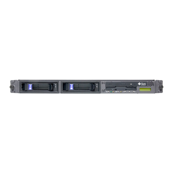
1.3.3 Sun Fire V20z Server Hardware System Orientation Before performing any service procedures, become familiar with the physical orientation and features of your Sun Fire V20z server. 1.3.3.1 Sun Fire V20z Front and Back Panels shows the front panel of the Sun Fire V20z server. FIGURE 1-1 Front Panel of the Sun Fire V20z Server FIGURE 1-1... - Page 23 ■ screen label “Slot 2 133MHz.” The slot on the motherboard that corresponds to PCI 1 is identified by the silk- ■ screen label “Slot 1 66MHz.” Chapter 1 Introduction to the Sun Fire V20z and Sun Fire V40z Servers...
-
Page 24: Sun Fire V20Z System Components
1.3.3.2 Sun Fire V20z System Components shows the locations of the components inside the Sun Fire V20z chassis. FIGURE 1-3 Location of System Components in the Sun Fire V20z Server FIGURE 1-3 Book Title without trademarks, or an abbreviated book title • January 2007... -
Page 25: Overview Of The Sun Fire V40Z Server
Overview of the Sun Fire V40z Server The Sun Fire V40z server is an AMD Opteron processor-based enterprise-class server. It is a 3 rack unit (3U) 4-processor (4P) system. The Sun Fire V40z server provides performance and value to an enterprise environment, offering significantly better performance than current solutions. -
Page 26: Sun Fire V40Z Features
1.4.2 Sun Fire V40z Features lists the main features of the Sun Fire V40z server. TABLE 1-2 Note – Visit the product web site for the most up-to-date information about the product features: http://www.sun.com/servers/entry/v40z. Sun Fire V40z Server Features TABLE 1-2... -
Page 27: Sun Fire V40Z Server Hardware System Orientation
USB connector Platform Power Locate button button and LED and LED System-fault Refer to Section 1.5.1.2, “Operator Panel” on page 1-12 for more information about the operator panel. Chapter 1 Introduction to the Sun Fire V20z and Sun Fire V40z Servers... - Page 28 Sun Fire V40z server. FIGURE 1-5 Back Panel of the Sun Fire V40z Server FIGURE 1-5 AC power connectors Vertical PCI card slots (6) (two power supplies shown) Horizontal PCI card slot Keyboard Mouse...
-
Page 29: Sun Fire V40Z System Components
1.4.3.2 Sun Fire V40z System Components shows the locations of the components inside the Sun Fire V40z chassis. FIGURE 1-6 Sun Fire V40z System Components FIGURE 1-6 Vertical PCI slots (6) (Horizontal PCI slot under power-supply cage not shown) Power-supply cage... -
Page 30: Shared Features Of The Sun Fire V20Z And Sun Fire V40Z Servers
Sun Fire V20z front panel. ■ FIGURE 1-1 shows the operator-panel location on the Sun Fire V40z front panel. FIGURE 1-4 ■ 1-12 Book Title without trademarks, or an abbreviated book title • January 2007... - Page 31 If a menu or data-entry screen displays for more than 30 seconds with no action taken, the menu or data entry is cancelled and the display returns to the idle/background state. Chapter 1 Introduction to the Sun Fire V20z and Sun Fire V40z Servers 1-13...
- Page 32 Clear DIMM Errs Clears memory-module errors. (For more information, refer to the chapter on “DIMM Faults” in the Sun Fire V20z and Sun Fire V40z Servers— Troubleshooting Techniques and Diagnostics Guide, 817-7184.) Display Port 80 Displays the last ten port 80 codes (in hex, 5 per line). Press any button to clear the display.
- Page 33 • The Select button displays the sensor readings in alphabetical order by unique ID. • For LEDs, the Select button toggles the state of the LED on or off. Chapter 1 Introduction to the Sun Fire V20z and Sun Fire V40z Servers 1-15...
- Page 34 Operator-Panel Menu Options (Continued) TABLE 1-4 Menu Menu Options Description Display HW Inv To use this option: • The Left and Right arrow buttons display inventory items. • The Select button displays the fields that are available for each item. •...
- Page 35 Use SP Hostname option, the host name displays in the top line. If you specify neither the Name for LCD nor the Use SP Hostname options, the numeric IP address is displayed. Chapter 1 Introduction to the Sun Fire V20z and Sun Fire V40z Servers 1-17...
-
Page 36: Front And Back Panel Leds
This LED blinks when a severe system fault, such as an over-voltage condition or an upper temperature limit, is detected. Refer to “System-Fault Events” in the Sun Fire V20z and Sun Fire V40z Servers— Troubleshooting Techniques and Diagnostics Guide, 817-7184. -
Page 37: Additional Options And Customer-Replaceable Components
Sun offers additional options as well as customer-replaceable components (CRUs) for the servers. The components for both the Sun Fire V20z and Sun Fire V40z servers are shown in TABLE 1-7 Caution – For important information about the components that can be used in the different releases of the servers, see Section 3.4.1, “Versions of the Sun Fire V20z... - Page 38 Additional Options and Customer-Replaceable Components for the Sun Fire V20z and TABLE 1-7 Sun Fire V40z Servers (Continued) Sun Fire Sun Fire Additional Customer-Replaceable V20z V40z Component Options Components • Opteron 248, 2.2 GHz, E Stepping 594-0661-xx F370-7711-xx • Opteron 250, 2.4 GHz, E Stepping...
- Page 39 DVD-ROM/Diskette combo unit 595-7348-xx F370-6656-xx DVD-ROM/Diskette combo unit 596-7485-xx F370-6906-xx Power Supplies Power supply F370-6636-xx Power supply (2nd power supply) 595-7500-xx F370-6916-xx Power-supply cage assembly F370-6921-xx Chapter 1 Introduction to the Sun Fire V20z and Sun Fire V40z Servers 1-21...
-
Page 40: Field-Replacement Units
Additional Options and Customer-Replaceable Components for the Sun Fire V20z and TABLE 1-7 Sun Fire V40z Servers (Continued) Sun Fire Sun Fire Additional Customer-Replaceable V20z V40z Component Options Components Cooling Fans Cooling fan (individual) F370-6639-xx Cooling fan (individual) F370-6922-xx Fan-cage assembly, front (holds four fans) - Page 41 The FRUs available for the Sun Fire V20z and Sun Fire V40z servers are shown in TABLE 1-8 To order these parts, contact your local Sun sales representative. You might have a part that is replaceable under warranty. For specific details regarding your warranty, refer to: http://www.sun.com/service/support/warranty/index.html...
- Page 42 1-24 Book Title without trademarks, or an abbreviated book title • January 2007...
-
Page 43: Powering On And Configuring Bios Settings
Before powering on the server for the first time, follow the instructions in the Sun Fire V20z and Sun Fire V40z Servers—Installation Guide to set up your server. This chapter contains the following sections: Section 2.1, “Powering On the Server”... - Page 44 Caution – Before you power on a Sun Fire V40z server for the first time, you must remove the packaging inserts from the server’s PCI card slots and CPU card slot to ensure proper airflow and cooling. You can discard these packaging inserts, which serve as protection during shipping.
-
Page 45: Powering Off The Server
If you have a Sun Fire V20z server, turn off the AC Power switch on the server ■ back panel to remove AC power. If you have a Sun Fire V40z server, disconnect all power cords from all power ■ supplies to remove AC power. -
Page 46: Escape Sequences For Remote Console Terminal
Escape Sequences for Remote Console Terminal If you are accessing your server using a remote console terminal, you might need to use the escape sequences shown in . If a regular function key is not working TABLE 2-1 properly, use the escape sequence listed next to it in the table. You will most likely need to use the escape sequences if you are using a Linux or Solaris OS. -
Page 47: Bios Setup Utility
During system boot, you can also press the F12 key to boot the network. To access the BIOS Setup utility remotely, you can log in by means of an SSH client. Refer to the Sun Fire V20z and Sun Fire V40z Servers—Server Management Guide, for more information about managing the server remotely. -
Page 48: Main Menu
2.4.1 Main Menu shows the options that are available from the BIOS Main menu. TABLE 2-2 BIOS Main Menu TABLE 2-2 Menu Option Description Default System Time Type the system time (hours:minutes:seconds) in the Current time specified fields and press Enter to save the data. Use the Tab key to move to the next field and use Shift+Tab to move to the previous field. - Page 49 BIOS Main Menu (Continued) TABLE 2-2 Menu Option Description Default Primary Sets the parameters of the IDE Primary Master/Subordinate Master and IDE Secondary Master slots. Press Enter to activate the (default: None) submenu screen to configure each of these settings. The submenu options include: Primary •...
-
Page 50: Advanced Menu
2.4.2 Advanced Menu shows the options that are available from the Advanced menu. TABLE 2-3 BIOS Advanced Menu TABLE 2-3 Menu Option Description Default Reset Clears the Extended System Configuration Data (ECSD). Configuration Options include: Yes and No. Data Multiprocessor Configures the MP Specification revision level. - Page 51 BIOS Advanced Menu (Continued) TABLE 2-3 Menu Option Description Default Chipset Options for advanced chipset features. Options include: Configuration • SRAT Table: Enables the ACPI 2.0 Static Resource Affinity Enabled Caution: Do not Table for OSs that support an SRAT and will disable node change the interleaving.
- Page 52 BIOS Advanced Menu (Continued) TABLE 2-3 Menu Option Description Default I/O Device Options for Peripheral menu. Options include: Configuration • PS/2 Mouse: Disabled prevents any installed PS/2 mouse Enabled from functioning, but frees up IRQ 12. Enabled forces the PS/2 mouse port to be enabled regardless of whether a mouse is present.
- Page 53 BIOS Advanced Menu (Continued) TABLE 2-3 Menu Option Description Default Setup items for configuring the specific PCI device slots: Configuration • Option ROM Scan: When disabled, the device is not Enabled Note: The Sun bootable but is still usable under the OS. When enabled, Fire V20z server initializes the device expansion ROM;...
- Page 54 BIOS Advanced Menu (Continued) TABLE 2-3 Menu Option Description Default Console Additional setup to configure console. Options include: Redirection • COM port address: If enabled, the console uses a port on On-board the motherboard. Options include: Disabled, On-board COM A COM A, On-board COM B.
-
Page 55: Security Menu
2.4.3 Security Menu shows the options that are available from the BIOS Security menu. TABLE 2-4 BIOS Security Menu TABLE 2-4 Menu Option Description Default Supervisor Displays whether a supervisor password has Clear Password Is: been entered for the system. Clear means such a password has not been used and Set means a supervisor password has been entered for the system. -
Page 56: Power Menu
2.4.4 Power Menu shows the options that are available from the BIOS Power menu. TABLE 2-5 BIOS Power Menu TABLE 2-5 Menu Option Description Default Resume on Time Wakes the system up at the specified time. Options are On or Off. Resume Time If turned on, specifies the time you want the system to 00.00.00... -
Page 57: Exit Menu
2.4.6 Exit Menu shows the options that are available from the BIOS Exit menu. TABLE 2-7 BIOS Exit Menu TABLE 2-7 Menu Item Description Exit Saving Changes Exits System Setup and saves changes to CMOS. Exit Discarding Exits System Setup without saving changes. Changes Load Setup Defaults Loads defaults for all setup items. -
Page 58: Booting From A Usb Diskette Device
Booting From a USB Diskette Device Only one diskette device is bootable on these servers. By default, the internal diskette device is the only device from which you can boot. To change the assignment of the diskette devices, so that the server boots from a USB diskette device rather than the internal diskette device, perform the following steps: 1. -
Page 59: Updating The Bios And Sp Firmware
Updating the BIOS and SP Firmware This section contains instructions on how to update the BIOS and SP firmware in the Sun Fire V20z and Sun Fire V40z servers. 2.6.1 Overview of the Update Procedure To update the BIOS and SP firmware, you must perform these steps: 1. -
Page 60: Powering On The Service Processor
If no DHCP service is available on the SP network, use the arrow buttons to ■ manually enter the network-information settings: IP address, netmask and default gateway or router. For more information, refer to the Sun Fire V20z and Sun Fire V40z Servers—Installation Guide (817-5246). 2.6.2.3 Resetting the Service Processor Note –... -
Page 61: Connecting Your Local Client To The Network
1. Press any of the three operator-panel buttons next to the front-panel LCD screen. The LCD displays the option Server Menu. 2. Press the Forward (right) button until the option “SP menu” is displayed. 3. Press the Select (center) button to confirm. 4. -
Page 62: Verify Bios And Firmware Versions
The SP is now set up and ready to be used to perform the server update. 2.6.3 Verify BIOS and Firmware Versions Ensure that you record the current SP settings and firmware revisions. The following steps explain how to verify the version of the BIOS and firmware currently installed on the server. -
Page 63: Performing The Server Update From A Solaris-Based Client
Open a new terminal window on your local Solaris machine. Create a New Directory This directory will serve as the central repository from which your Sun Fire V20z and Sun Fire V40z servers will download the new firmware during the update process. ●... -
Page 64: Mount The Nsv Share On The Service Processor
For a Sun Fire V20z server: ■ Download the following files into the directory /export/home/v20z on your local Solaris machine. nsv_V2_4_0_6.zip nsv-v20z-bios-fw_V2_4_0_6.zip For a Sun Fire V40z server: ■ Download the following files into the directory /export/home/v40z on your local Solaris machine. nsv_V2_4_0_6.zip nsv-v40z-bios-fw_V2_4_0_6.zip Unzip the NSV Package Files ●... -
Page 65: Perform The Sp Update
<SP_username> is your user name for logging in to the SP and <SP_IP> represents the SP IP address that is displayed on the front-panel LCD display of the Sun Fire V20z or Sun Fire V40z server. 5. At the ssh prompt, enter one of the following commands: For a Sun Fire V20z server, enter: ■... - Page 66 For a Sun Fire V20z server, enter: ■ java -jar /export/home/v20z/update_server/V2.2.0.6/updateServer.jar - /export/home/v20z/sw_images/sp/spbase/V2.3.0.15/install.ima ge -p 50000 For a Sun Fire V40z server, enter: ■ java -jar /export/home/v40z/update_server/V2.2.0.6/updateServer.jar - /export/home/v40z/sw_images/sp/spbase/V2.3.0.15/install.ima ge -p 50000 The following message appears in the terminal window: The SP update process will take several minutes to complete during which the SP will be rebooted.
- Page 67 Step 2–Start the Update Process From the Service Processor Return to the terminal window with the SSH connection to the SP. ● Launch the update process with the following command: sp update flash all -i <ip_address_solaris_machine> -p 50000 The SP executes the command and reboots itself. The reboot process takes a few minutes.
-
Page 68: Perform The Bios Update
For a Sun Fire V20z server, enter: ■ platform set os state update-bios /mnt/sw_images/platform/firmware/bios/V1.33.7.2/bios.sp For a Sun Fire V40z server, enter: ■ platform set os state update-bios /mnt/sw_images/platform/firmware/bios/V2.33.7.2/bios.sp This update process might take several minutes before any output is returned. The output in your terminal window should look similar to the following: This command may take several minutes. -
Page 69: Verify The Updates
For the beginning section of this message, see “Console Output After Successful Update on a Sun Fire V20z Server” on page 2-36 “Console Output After Successful Update on a Sun Fire V40z Server” on page 2-37. 2.6.4.6 Housecleaning Tasks The update procedure is now complete. Please note: If the local client from which you performed the update procedure will remain at ■... -
Page 70: Performing The Server Update From A Linux-Based Client
Open a new terminal window on your local Linux machine. Create a New Directory This directory will serve as the central repository from which your Sun Fire V20z and Sun Fire V40z servers will download the new firmware during the update process. ●... -
Page 71: Mount The Nsv Share On The Service Processor
For a Sun Fire V20z server: ■ Download the following files into the directory /export/home/v20z on your local Linux machine. nsv_V2_4_0_6.zip nsv-v20z-bios-fw_V2_4_0_6.zip For a Sun Fire V40z server: ■ Download the following files into the directory /export/home/v40z on your local Linux machine. nsv_V2_4_0_6.zip nsv-v40z-bios-fw_V2_4_0_6.zip Unzip the NSV Package Files ●... - Page 72 5. Restart the NFS service using one of the following methods, depending on what type of Linux you are using: For SUSE Linux, use these commands: ■ a. Restart the NFS service: /etc/init.d/nfsserver stop /etc/init.d/nfsserver start b. Use the command below to verify that /export/home/v20z or /export/home/v40z is listed: showmount -e localhost 2-30...
-
Page 73: Perform The Sp Update
<SP_username> is your user name for logging in to the SP and <SP_IP> represents the SP IP address that is displayed on the front-panel LCD display of the Sun Fire V20z or Sun Fire V40z server. 9. At the ssh prompt, enter one of the following commands: For a Sun Fire V20z server, enter: ■... - Page 74 Enter one of the following commands in a terminal window on your local Linux machine: Sun Fire V20z server: java -jar /export/home/v20z/update_server/V2.2.0.6/updateServer.jar -f /export/home/v20z/sw_images/sp/spbase/V2.3.0.15/install.image -p 50000 Sun Fire V40z server: java -jar /export/home/v40z/update_server/V2.2.0.6/updateServer.jar -f /export/home/v40z/sw_images/sp/spbase/V2.3.0.15/install.image -p 50000 2-32 Book Title without trademarks, or an abbreviated book title • January 2007...
- Page 75 Note – Enter the command on one continuous line at the prompt. The following message appears in the terminal window: The SP update process will take several minutes to complete during which the SP will be rebooted. You may now execute the "sp update flash all"...
-
Page 76: Perform The Bios Update
For a Sun Fire V20z server, enter: ■ platform set os state update-bios /mnt/sw_images/platform/firmware/bios/V1.33.7.2/bios.sp For a Sun Fire V40z server, enter: ■ platform set os state update-bios /mnt/sw_images/platform/firmware/bios/V2.33.7.2/bios.sp This update process might take several minutes before any output is returned. The output in your terminal window should look similar to the following: This command may take several minutes. -
Page 77: Verify The Updates
For the beginning section of this message, see “Console Output After Successful Update on a Sun Fire V20z Server” on page 2-36 “Console Output After Successful Update on a Sun Fire V40z Server” on page 2-37. 2.6.5.6 Housecleaning Tasks The update procedure is now complete. Please note: If the local client from which you performed the update procedure will remain at ■... -
Page 78: Console Output After Successful Update On A Sun Fire V20Z Server
Copyright 1985-2002 Phoenix Technologies Ltd. All Rights Reserved Production RELEASE: System BIOS Revision = V1.34.4.2 SP Interface (PRS) Revision = 97 SP - BIOS Interface Active xxxxxxxxxxxxxxxxxxxxxxxxxx Sun Microsystems 2-36 Book Title without trademarks, or an abbreviated book title • January 2007... -
Page 79: Console Output After Successful Update On A Sun Fire V40Z Server
Sun Fire V20z xxxxxxxxxxxxxxxxxxxxxxxxxx CPU0 = AMD Opteron(tm) Processor 250 CPU1 = AMD Opteron(tm) Processor 250 2 Processors Detected, CG - CG PCIX - Slot0: PCIX-66 Slot1: PCIX-133 4031M System RAM Passed 1024K Cache SRAM Passed ATAPI CD-ROM: CD-224E Mouse initialized <...continued>... - Page 80 Sun Microsystems Sun Fire V40z xxxxxxxxxxxxxxxxxxxxxxxxxx CPU0 = AMD Opteron(tm) Processor 848 CPU1 = AMD Opteron(tm) Processor 848 CPU2 = AMD Opteron(tm) Processor 848 CPU3 = AMD Opteron(tm) Processor 848 4 Processors Detected, CG - CG - CG - CG...
-
Page 81: Maintaining The Sun Fire V20Z Server
C H A P T E R Maintaining the Sun Fire V20z Server This chapter describes how to add, replace, and configure components in the Sun Fire V20z server after it has been set up. For instructions on maintaining the Sun Fire V40z server, see Chapter Caution –... -
Page 82: Tools And Supplies Needed
Tools and Supplies Needed #2 crosshead screwdriver ■ Antistatic wrist strap ■ Alcohol pads (for CPU replacement only) ■ Book Title without trademarks, or an abbreviated book title • January 2007... -
Page 83: Powering Off The Server And Removing The Cover
Powering Off the Server and Removing the Cover Perform this procedure to observe safety guidelines when you are powering off the system and removing the cover for a maintenance procedure in this chapter: 1. If the system OS is running, perform a shutdown of the OS, then press and release the platform Power button on the front panel. -
Page 84: Installing The Sun Fire V20Z System Cover
Removing the Cover From the Sun Fire V20z Server FIGURE 3-1 3.2.1 Installing the Sun Fire V20z System Cover Follow the procedure in this section to install the system cover onto the Sun Fire V20z server. 3.2.1.1 System Cover Installation Notes Before installing the Sun Fire V20z system cover, follow these guidelines: Remove all peripheral cables from PCI cards before installing the cover. -
Page 85: Installing The System Cover
3.2.1.2 Installing the System Cover Follow this procedure to install the system cover: 1. Guide the sides of the cover into the grooves on either side of the chassis. 2. Lower the front end of the cover and ensure that the sides engage fully down into the grooves. -
Page 86: Scsi Id Assignments
3.3.1 SCSI ID Assignments The ID assignments for the SCSI hard disk drive (HDD) connectors on the SCSI backplane are shown in , when viewing the HDDs from the front of the FIGURE 3-3 server. SCSI slot 0 is the left drive bay. ■... -
Page 87: Versions Of The Sun Fire V20Z Server
3.4.1 Versions of the Sun Fire V20z Server A number of different versions of the Sun Fire V20z server have been released. Due to changes on the motherboard as well as in the BIOS and firmware, a number of components—such as memory VRMs and CPU VRMs—are not interchangeable among the various releases. -
Page 88: Super Fru Chassis Pn 380-1194
Solaris OS Install-Time Update (ITU) from the web site. This ITU is required during OS installation. If you want to install the Solaris 9 OS on an updated release of the Sun Fire V40z server, you must also download this Solaris OS ITU from the web site. This ITU is required during OS installation. -
Page 89: No Mixing Of Cpu Stepping Versions
The Solaris OS ITU is available from the product web site: http://www.sun.com/servers/entry/v20z/downloads.html 3.4.2 No Mixing of CPU Stepping Versions A number of different versions of the Sun Fire V20z server have been released with CPUs of different stepping versions. If you order a CPU option to add or replace a CPU in your server, do not mix CPUs of different stepping versions. - Page 90 All Rights Reserved Production RELEASE: System BIOS Revision = V1.33.5.2 SP Interface (PRS) Revision = 92 SP - BIOS Interface Active xxxxxxxxxxxxxxxxxxxxxxxxxx Sun Microsystems Sun Fire V20z xxxxxxxxxxxxxxxxxxxxxxxxxx CPU = AMD Opteron(tm) Processor 250 2 Processors Detected, CG - CG...
- Page 91 For more information, refer to the “Serial Over LAN” section in Chapter 4 of the Sun Fire V20z and Sun Fire V40z Servers—Server Management Guide (817-5249). 2. Launch the SOL session from an SP command-line interface (CLI) to connect to the platform console remotely.
- Page 92 9. In the SP SOL session that you launched in Step 1, you now see the output of the BIOS CPU step screen. For a sample of this output, see Step 1 in the previous procedure in “Verifying the Stepping Version in a Local Server” on page 3-10.
-
Page 93: Customer-Replaceable Unit Replacement Procedures
10. During the server’s memory self-test, terminate the remote session in order to pause the screen: a. Press Control-e. b. Press the ‘c’ key. c. Press the period key (.). 11. Verify the stepping version of the CPUs in the line similar to the following examples: 2 Processors Detected, CG - CG 2 Processors Detected, E4 - E4... -
Page 94: I/O Board
CPU voltage-regulator modules (see Section 3.5.10, “CPU Voltage-Regulator ■ Modules” on page 3-33) Memory (see Section 3.5.11, “Memory Modules” on page 3-35) ■ Battery (see Section 3.5.12, “System Battery” on page 3-38) ■ Cable kit (see Section 3.5.13, “Cable Kit” on page 3-40) ■... -
Page 95: Pci Card
Use only +3V PCI cards in your Sun Fire V20z and V40z servers. For information about how to resolve PCI and PCI-X hot-plug problems, see the Sun Fire V20z and Sun Fire V40z Servers—Troubleshooting Techniques and Diagnostics Guide. 3.5.2.1... -
Page 96: Pci Card Installation Notes
Note – LSI MegaRAID cards have been qualified for use only with external storage arrays when installed in the Sun Fire V20z server. Therefore, there is no internal cable exchange, and this card can be installed in the Sun Fire V20z server with the same instructions as any other PCI card. - Page 97 a. Unfasten all cables connected to the card. b. Withdraw the card and riser from the PCI card connector on the motherboard. c. Remove the PCI card from the riser. Note – If the PCI card is being removed, but not replaced with another card: Reinstall the empty riser assembly in the empty PCI-card connector on the motherboard.
-
Page 98: Scsi Hard Disk Drive And Carrier
Installing the PCI Card and Riser FIGURE 3-7 g. Pivot the card latch up and then slide it down until it captures the PCI card bracket. Tighten the screw to secure the latch (refer to FIGURE 3-6 h. Before reinstalling the cover on the server, check the routing of all cables for obstructions. -
Page 99: Scsi Backplane
Opening the Release Latch on the SCSI Hard Disk Drive Carrier FIGURE 3-8 3. Grasp the carrier bezel with both hands and carefully pull the carrier out of the drive bay. Note – Avoid using the arm to remove the carrier. 4. - Page 100 Note – Avoid using the arm to remove the carrier. Opening the Release Latch on the SCSI Hard Disk Drive Carrier FIGURE 3-9 3-20 Book Title without trademarks, or an abbreviated book title • January 2007...
- Page 101 4. Remove the screw that holds the center air baffle and remove the baffle from the server (see FIGURE 3-10 Removing the Center Air Baffle FIGURE 3-10 5. Remove the second processor fan from the right (see FIGURE 3-11 a. Unplug the fan’s power connector from the motherboard. b.
- Page 102 Removing a Processor Cooling Fan FIGURE 3-11 6. Remove the CPU VRM for CPU 1 (left-side CPU) by pulling it straight up, out of its sockets (see FIGURE 3-12 Removing the CPU 1 VRM FIGURE 3-12 7. Disconnect the 5-pin power cable, the small, flat cable and the 68-pin ribbon signal cable from the SCSI backplane (see FIGURE 3-13 Caution –...
-
Page 103: Cd-Rom/Dvd-Rom/Diskette Drive Assembly
Uncabling the SCSI Backplane FIGURE 3-13 8. Unfasten the two screws that secure the backplane to the chassis. 9. Lift the SCSI backplane up and out of the chassis (see FIGURE 3-14 10. To install the new SCSI backplane, reverse Step 3 through Step... - Page 104 Note – Removable drives are fragile components that must be handled with care. To prevent damage to the system, damage to a removable drive, or loss of information, observe these precautions: Before removing a diskette drive or CD-ROM/DVD-ROM drive, ensure that a diskette or disc is not in the drive. Ensure that the CD-ROM/DVD-ROM tray is closed.
- Page 105 3. Unfasten the CD-ROM/DVD-ROM/diskette drive ribbon cables from the motherboard (see FIGURE 3-15 Caution – Use care with the small flat cables. They are extremely fragile. Uncabling the CD-ROM/DVD-ROM/Diskette Drive Assembly FIGURE 3-15 4. Unfasten the single screw securing the CD-ROM/DVD/diskette drive assembly to the chassis (see FIGURE 3-16 5.
-
Page 106: Operator-Panel Board And Lcd Assembly
Removing the CD-ROM/DVD-ROM/Diskette Drive Assembly FIGURE 3-16 Caution – Move the assembly by grasping it by its sides. Do not to push on the CD-ROM/DVD-ROM tray. 6. Lift the rear of the assembly slightly and withdraw it from the chassis. 7. - Page 107 2. Remove the top cover from the server. 3. Remove the CD-ROM/DVD-ROM/diskette drive assembly. Refer to Section 3.5.5, “CD-ROM/DVD-ROM/Diskette Drive Assembly” on page 3-24. Chapter 3 Maintaining the Sun Fire V20z Server 3-27...
- Page 108 4. Remove the two screws securing the LCD to the front panel (see FIGURE 3-17 Removing the LCD FIGURE 3-17 5. Unfasten the ribbon cable connecting the operator-panel board to the motherboard (see FIGURE 3-18 Caution – Use care with the small, flat cables. They are extremely fragile. Uncabling and Removing the Operator-Panel Board FIGURE 3-18 6.
-
Page 109: Power Supply
8. To install the new operator-panel board and LCD assembly, reverse Step 3 through Step 9. Before reinstalling the cover on the server, check the routing of all cables for obstructions. 3.5.7 Power Supply The following procedure describes how to remove and replace the power supply. 1. - Page 110 4. Disconnect the three power-supply cables from the motherboard (see FIGURE 3-20 Disconnecting the Power-Supply Cables FIGURE 3-20 5. Unfasten the single screw securing the power supply to the rear of the chassis (see FIGURE 3-21 Removing the Power Supply FIGURE 3-21 6.
-
Page 111: Cooling Fans
3.5.8 Cooling Fans Note – System cooling might be affected by dust and contaminant build-up. It is recommended that systems be opened and checked approximately every six months or more often in dirty operating environments. Check system heatsinks, fans, and air openings. -
Page 112: Memory Voltage-Regulator Modules
Removing the Cooling Fans (Processor Fan Shown) FIGURE 3-23 6. Pull the fan straight up to remove it from the fan tray. 7. To install the new cooling fan, reverse Step 4 through Step Caution – Ensure that the fan airflow direction is correct (front to rear) by installing the fan so that the airflow direction arrow points toward the rear of the chassis. -
Page 113: Cpu Voltage-Regulator Modules
2. Remove the top cover from the server. 3. Identify the memory VRM that must be replaced. The memory VRM is in the outer slot, furthest from the CPU. 4. Remove a memory VRM by pressing down on the ejectors at both ends of the socket (see FIGURE 3-24 Removing a Memory VRM... -
Page 114: Replacing A Cpu Vrm
Sun Fire V40z server (chassis PN 380-1010). The CPU VRM for the second updated release of the Sun Fire V20z server can ■ also be used in the updated release of the Sun Fire V40z server (chassis PN 380-1206). 3.5.10.2 Replacing a CPU VRM 1. -
Page 115: Memory Modules
5. To install the new VRM, press the new VRM into the empty socket until it snaps into place, ensuring that the key in the CPU VRM aligns with the key in the connector. 6. Before reinstalling the cover on the server, check the routing of all cables for obstructions. -
Page 116: Replacing A Memory Module
DIMMs must be installed in matched pairs (one bank at a time). The two DIMMs ■ in a bank must be of the same size, type, and vendor. Each CPU can support two banks of DIMMs. While each bank must contain a pair ■... -
Page 117: System Battery
4. Remove a memory module by pressing down on the ejectors at both ends of the memory module’s socket (see FIGURE 3-26 Removing a Memory Module FIGURE 3-26 5. To install the new memory module, ensure that the memory module socket’s ejectors are open (rotated outward) to allow the new module to be inserted. -
Page 118: Replacing The System Battery
Caution – Do not attempt to open or service batteries. The battery contains lithium and can explode if not properly used, handled, or disposed of. 3.5.12.1 Replacing the System Battery 1. Power off the server, including any attached peripherals, and disconnect the server from the electrical outlet. -
Page 119: Cable Kit
3.5.13 Cable Kit The following procedure describes how to remove and replace the following cables: 5-pin power cable connecting the SCSI backplane to the motherboard (1) ■ 68-pin ribbon cable connecting the SCSI backplane to the motherboard (2) ■ Flat cable connecting the SCSI backplane to the motherboard (3) ■... - Page 120 System Cables in the Sun Fire V20z Server FIGURE 3-28 The two halves of the 5-pin SCSI backplane power cable connector (1) are secured ■ with a hook. The 68-pin SCSI ribbon cable (2) has no locking mechanism. ■ The small, flat cables (3, 4, 5, and 6) are attached using two different types of ■...
- Page 121 Types of Cable Connectors and Release Mechanisms FIGURE 3-29 Chapter 3 Maintaining the Sun Fire V20z Server 3-41...
-
Page 122: Cpus And Heat Sinks
3.5.14 CPUs and Heat Sinks Note – System cooling might be affected by dust and contaminant build-up. It is recommended that systems be opened and checked approximately every six months or more often in dirty operating environments. Check system heatsinks, fans, and air openings. -
Page 123: Removing A Heat Sink And Cpu
3. Remove the CPU VRM for CPU 1. Refer to Section 3.5.10.2, “Replacing a CPU VRM” on page 3-34. If the CPU VRM for CPU 1 is not removed, the server will not boot. 4. Remove the memory DIMMs and the memory VRM for CPU 1. Refer to Section 3.5.9, “Memory Voltage-Regulator Modules”... - Page 124 Removing the Securing Clip and Heat Sink for Stepping Versions “C0” and FIGURE 3-31 “CG” CPUs For a heat sink installed in the second updated release (chassis PN 380-1194) of ■ the server (for CPUs of stepping versions “E”): Loosen the screws evenly on each side of the heat sink. Remove the screws and captive springs that secure the heat sink (the washers remain fixed to the surface of the heat sink).
-
Page 125: Removing A Heat Sink From The Second Updated Release (Chassis Pn 380-1194)
Caution – The heat sink can become extremely hot. Ensure that it has had sufficient time to cool before handling. 5. Twist the heat sink slightly to the right or left to break the seal with the thermal grease. 6. Lift the heat sink away from the CPU. 7. -
Page 126: Installing A Heat Sink Into The Second Updated Release (Chassis Pn 380-1194)
Note – Improper removal and installation of the heat sink can strip the threads on the heat sink spring nuts. To ensure that this does not occur, remove and install the heat sink only according to the instructions in this procedure. 1. - Page 127 2. Use the plastic card from your Processor Replacement Kit to distribute the grease carefully. Scrape off any excess grease until only an extremely thin and uniform layer remains. Any voids or crevices can create air pockets, so ensure that coverage is thin but thorough.
-
Page 128: Installing A Cpu And Heat Sink
6. Place the rear spring nut (the one nearest the PCI support post) over the rear mounting post, and without using a tool, hand-tighten the spring nut as far as it allows. Caution – Do not use a tool to tighten the spring nut. Using a tool might cause cross-threading. - Page 129 2. Ensure that the CPU socket release lever is in the fully open, perpendicular position (see FIGURE 3-35 3. Align the small triangle, on the corner of the CPU, with the triangle on the corner of the socket. Installing a CPU Into Its Socket FIGURE 3-35 4.
- Page 130 Caution – If the heat sink is moved too much during its installation, the layer of thermal grease might become uneven, leading to component damage. 11. After correctly aligning the heat sink, proceed according to the type of heat sink that you have: If you have a heat sink from the original release (chassis PN 380-0979) or the first ■...
- Page 131 Type A Spring Assembly (With External Threads) FIGURE 3-36 Spring assembly Heat Sink Washer Base of heat sink Standoff b. Carefully press down firmly and evenly on the heat sink, to hold it securely in place while you install the spring assemblies. Note –...
-
Page 132: Super Fru
i. Lightly hold the heat sink in place as you complete the installation with the appropriate tool. j. Tighten the rear spring assembly three turns. k. Tighten the front spring assembly three turns. l. Continue to alternate the tightening of the rear and front spring assemblies until both spring assemblies “bottom out”... -
Page 133: Sun Fire V20Z Indicators, Switches, And Jumpers
I/O board (see Section 3.5.1, “I/O Board” on page 3-15) ■ PCI card(s) and risers (2) (see Section 3.5.2, “PCI Card” on page 3-16) ■ Hard disk drive (1-2) and carrier (2) (see Section 3.5.3, “SCSI Hard Disk Drive and ■... - Page 134 Sun Fire V20z Motherboard, Showing Jumper Locations FIGURE 3-37 Server rear J110 SP indicators area (D46, D47, D48, D56, D57) J108 Server front defines the functions of the switches and jumpers shown in TABLE 3-5 FIGURE 3-37 Switches and Jumpers TABLE 3-5 Component Function or Definition...
- Page 135 Switches and Jumpers (Continued) TABLE 3-5 Component Function or Definition J110 Clear CMOS: Pins 1+2 = clear CMOS on next boot, Pins 2+3 = retain CMOS settings on next boot J108 NPUI Power supply: Pins 1+2 = disabled, Pins 2+3 = enabled J105 Reserved (not shown in figure) defines the actions and meaning of the SP indicators shown in...
-
Page 136: Clear-Cmos Jumper
Power Indicators (Continued) TABLE 3-7 Indicator Description Color CPU 1 power OK Green Thor power good Green PRS internal error SCSI channel A indicator Green Reserved Reserved SCSI controller operational Green 3.6.2 Clear-CMOS Jumper The location of the Clear-CMOS jumper (J110) on the Sun Fire V20z motherboard is shown in . - Page 137 Chapter 3 Maintaining the Sun Fire V20z Server 3-57...
- Page 138 3-58 Book Title without trademarks, or an abbreviated book title • January 2007...
-
Page 139: Maintaining The Sun Fire V40Z Server
Maintaining the Sun Fire V40z Server This chapter describes how to add, replace, and configure components in the Sun Fire V40z server after it has been set up. For instructions on maintaining the Sun Fire V20z server, see Chapter Caution – Before touching or replacing any component inside the server, disconnect all external cables. -
Page 140: Tools And Supplies Needed
Tools and Supplies Needed #2 crosshead screwdriver ■ Antistatic wrist strap ■ Alcohol pads (for CPU replacement only) ■ Book Title without trademarks, or an abbreviated book title • January 2007... -
Page 141: Powering Off The Server And Removing The Cover
6. Loosen the captive screw on the cover latch, then rotate the latch toward the system rear to push back the cover (see FIGURE 4-1 7. Lift up the cover and remove it from the server. Chapter 4 Maintaining the Sun Fire V40z Server... -
Page 142: Installing The Sun Fire V40Z System Cover
Installing the Sun Fire V40z System Cover 4.2.1.1 System Cover Installation Notes Before installing the Sun Fire V40z system cover, follow these guidelines: Remove all peripheral cables from PCI cards before installing the cover. If you ■ install the server cover with PCI card cables installed, a lip on the edge of the... -
Page 143: Installing The System Cover
3. Rotate the lever clockwise until the cover latches in place. 4. Secure the fastener to lock the lever in place. Locations of Sun Fire V40z Components Refer to the top-down view of the server in to locate components before FIGURE 4-2 performing the remove and replace procedures. - Page 144 Locations of System Components in the Sun Fire V40z Server, Top-Down View FIGURE 4-2 System battery Power-supply (under power cage assembly supply cage) (up to 2 power supplies) Horizontal Vertical PCI slot and PCI slots (6) PCI riser (under power...
-
Page 145: Scsi Id Assignments
4.3.1.2 Solaris-based Server The Solaris boot disk must be installed in SCSI slot 0. Releases of the Sun Fire V40z Server The information in this section applies to: The original release (chassis part number [PN] 380-1010) of the server ■... -
Page 146: Versions Of The Servers
4.4.1 Versions of the Servers An updated version of the Sun Fire V40z server has been released. Due to changes on the motherboard as well as in the BIOS and firmware, a number of components—such as memory VRMs and CPU VRMs—are not interchangeable between the original and updated releases. -
Page 147: Super Fru Chassis Pn F380-1206
Solaris OS Install-Time Update (ITU) from the web site. This ITU is required during OS installation. If you want to install the Solaris 9 OS on an updated release of the Sun Fire V40z server, you must also download this Solaris OS ITU from the web site. This ITU is required during OS installation. -
Page 148: No Mixing Of Cpu Stepping Versions
Due to the power requirements and height restrictions, the stepping version “E” CPUs work only in the Sun Fire V40z server release PN 380-1206. In a two or four CPU configuration of the Sun Fire V40z server, all CPUs must be the same stepping version and the same speed. - Page 149 2 Processors Detected, E4 - E4 4. To continue with the reboot, press any key. Verifying the Stepping Version in a Remote Server To verify the stepping version of your CPU(s) in a remote server: Chapter 4 Maintaining the Sun Fire V40z Server 4-11...
- Page 150 1. Enable the Serial-Over-LAN (SOL) feature on the SP. For more information, refer to the “Serial Over LAN” section in Chapter 4 of the Sun Fire V20z and Sun Fire V40z Servers—Server Management Guide. 2. Launch the SOL session from a SP command-line interface (CLI) to connect to the platform console remotely.
- Page 151 Press the period key (.). 11. Verify the stepping version of the CPUs in the line similar to the following examples: 2 Processors Detected, CG - CG 2 Processors Detected, E4 - E4 Chapter 4 Maintaining the Sun Fire V40z Server 4-13...
-
Page 152: Customer-Replaceable Unit Replacement Procedures
Customer-Replaceable Unit Replacement Procedures Caution – Before touching or replacing any component inside the server, disconnect all external cables. If possible, place the server on a grounded electrostatic-discharge (ESD) pad and always wear a properly grounded, antistatic wrist strap. Caution – The auxiliary CPU card is not a hot-swappable component. You must power down the server before removing the card. -
Page 153: Pci Card
4-86) ■ Caution – The Sun Fire V40z server weighs about 75 pounds (34 kilograms). Use caution when lifting or moving the server to avoid personal injury. Always load a rack from the bottom up and load the heaviest item in the lowest rack position. -
Page 154: Supported Pci Cards
PCI Card Installation Notes The following procedures describe how to add or replace a PCI card. The seven PCI card slots comprise four different types of slots on the Sun Fire V40z server (see FIGURE 4-4 Four full-length, 133-MHz/64-bit, vertical slots ■... -
Page 155: Sun Fire V40Z Server Pci Card Slot Locations
4.5.1.3 Sun Fire V40z Server PCI Card Slot Locations Locations of the PCI Card Slots in the Sun Fire V40z Server FIGURE 4-4 4.5.1.4 Installing a Vertical PCI Card in a Vertical Slot Follow these steps to install a vertical mount PCI card in one of the server’s six vertical slots (see for location). -
Page 156: Figure
Removing or Installing a Vertical PCI Card in a Vertical Slot With an MRL FIGURE 4-5 Removing or Installing a Vertical PCI Card in a Vertical Slot Without an MRL FIGURE 4-6 4-18 Book Title without trademarks, or an abbreviated book title • January 2007... -
Page 157: Installing A Horizontal Pci Card And Riser
Caution – Before you power on a Sun Fire V40z server the first time, you must open the top cover and remove the foam packaging insert from the server’s PCI slots to ensure proper airflow and cooling. You can discard this packaging insert, which serves as protection during shipping. -
Page 158: Figure
3. Remove the power-supply cage assembly. Refer to Section 4.5.9.2, “Replacing a Power-Supply Cage Assembly” on page 4-44. 4. On the outside of the server back panel, loosen the screw holding the card latch (see FIGURE 4-7 5. Raise the card latch as far as possible and then pivot it toward the rear of the chassis. -
Page 159: Figure
12. Reinstall the power-supply cage assembly. Refer to Section 4.5.9.2, “Replacing a Power-Supply Cage Assembly” on page 4-44. 13. Before reinstalling the cover on the server, check the routing of all cables for obstructions. Chapter 4 Maintaining the Sun Fire V40z Server 4-21... -
Page 160: Installing An Lsi Megaraid Card With Battery Backup Into The Original Release (Chassis Pn 380-1010)
When installing the LSI MegaRAID card with battery backup into the original release (chassis PN 380-1010) of the Sun Fire V40z server, you must plug the extender cable (included with the card) into the system’s SCSI signal cable. -
Page 161: Installing An Lsi Megaraid Card With Battery Backup Into An Updated Release (Chassis Pn 380-1206)
When installing the LSI MegaRAID card with battery backup into the updated release (chassis PN 380-1206) of the Sun Fire V40z server, you replace the SCSI signal cable in the system with the new SCSI signal cable that is included with the card. - Page 162 7. Route the new SCSI signal cable along the chassis wall, behind CPU 0 DDR VRM (see FIGURE 4-10 8. Continue routing the new SCSI signal cable between SCSI connector A and the power-supply cage connector (see FIGURE 4-10 9. Continue routing the new SCSI signal cable parallel with the horizontal PCI slot, then fold it over the top of the LSI MegaRAID card that is installed in the riser (see FIGURE 4-10...
-
Page 163: Scsi Hard Disk Drive And Carrier
SCSI Signal Cable and Connectors (Updated Release of the Sun Fire V40z FIGURE 4-10 Server) New SCSI cable routing path Position of card when installed in riser CPU 0 DDR VRM Power supply SCSI connector A SCSI backplane connector cage connector 4.5.2... -
Page 164: Dvd-Rom/Diskette Drive Assembly
2. Squeeze the release latch and carefully swing the arm to the left as far as it will go (see FIGURE 4-11 Opening the Release Latch on the SCSI Hard Disk Drive Carrier FIGURE 4-11 3. Grasp the carrier bezel with both hands and carefully pull the carrier out of the drive bay. - Page 165 DVD-ROM/diskette drive assembly and remove the assembly from the server (see FIGURE 4-12 Feed the cable through the openings in the chassis as you remove the assembly. 5. Disconnect the ribbon cable connector from the rear of the assembly. Chapter 4 Maintaining the Sun Fire V40z Server 4-27...
- Page 166 Removing the DVD-ROM/Diskette Drive Assembly FIGURE 4-12 6. To install the new assembly, connect the ribbon cable connector to the rear of the assembly. 7. Align the assembly with the bay opening and press in firmly on both corners of the assembly until the latch clicks into place. As you insert the assembly, pull the excess cable back in through the openings in the chassis.
-
Page 167: Front Bezel And Cpu Card
(see FIGURE 4-13 3. Lift the bezel off of the lower mounting slots, so that the hooks are clear of the chassis, and set the bezel aside. Chapter 4 Maintaining the Sun Fire V40z Server 4-29... - Page 168 Removing the Front Bezel FIGURE 4-13 4. Open the CPU card door by pressing down on the two buttons on both sides of the door (see FIGURE 4-14 The CPU card door, located under the hard drive bays, provides access to the CPU card.
- Page 169 Section 4.5.13.2, “Replacing a CPU on the Optional CPU Card” on page 4-64 ■ 9. Install components to the new CPU card (either as new components or as components you are transferring from an old CPU card). Refer to the following procedures: Chapter 4 Maintaining the Sun Fire V40z Server 4-31...
-
Page 170: Installing The Cpu Card And Front Bezel
Section 4.5.10.2, “Replacing a Memory VRM on the CPU Card” on page 4-47 ■ Section 4.5.11.3, “Replacing a CPU VRM on the CPU Card” on page 4-52 ■ Section 4.5.12.3, “Replacing a Memory Module on the CPU Card” on page 4-58 ■... -
Page 171: Operator Panel And Lcd Assembly
4-3. 2. Remove the top cover from the server. 3. Remove the two non-captive screws and loosen the single captive screw that secures the assembly to the chassis (see FIGURE 4-17 Chapter 4 Maintaining the Sun Fire V40z Server 4-33... -
Page 172: Scsi Backplane Assembly
Removing the Operator Panel and LCD Assembly FIGURE 4-17 4. Pull the assembly out from the chassis front about 1 inch (25.4 mm), until you can reach the two cables attached to the rear of the assembly. 5. Disconnect the two cables from the circuit board connectors on the rear of the assembly. - Page 173 FIGURE 4-18 6. Loosen the two captive screws that secure the SCSI backplane assembly to the chassis (see FIGURE 4-19 7. Lift the SCSI backplane assembly up and out of the chassis. Chapter 4 Maintaining the Sun Fire V40z Server 4-35...
-
Page 174: Cooling Fans
If necessary, clean systems by brushing or blowing contaminants from the system or by carefully vacuuming contaminants from the system. The 12 replaceable cooling fans in the Sun Fire V40z server plug into two different fan-cage assemblies. Use the correct procedure in this section: To replace an individual cooling fan, see Section 4.5.7.2, “Replacing an Individual... -
Page 175: Fan Numbering
4.5.7.1 Fan Numbering The cooling fans in a Sun Fire V40z server are numbered as shown in FIGURE 4-20 For the rear fans, the fan numbers are imprinted on the plastic of the rear fan-cage ■ assembly. For the front fans, the fan numbers are imprinted on the center air baffle that ■... - Page 176 3. Remove the center air baffle (see FIGURE 4-18 Lift the rear edge of the baffle, then move it toward the rear of the server to disengage the hooks on the front edge of the baffle. 4. Identify the fan(s) to be replaced in either the front or rear fan cage. 5.
-
Page 177: Replacing The Front Fan-Cage Assembly
4.5.7.3 Replacing the Front Fan-Cage Assembly Caution – On the updated release of the Sun Fire V40z server (chassis PN 380-1206), if you remove the front or rear fan-cage assembly from the motherboard while the server is powered on and running, the server will automatically perform a hard power-off. -
Page 178: Replacing The Rear Fan-Cage Assembly
4.5.8.4 Replacing the Rear Fan-Cage Assembly Caution – On the updated release of the Sun Fire V40z server (chassis PN 380- 1206), if you remove the front or rear fan-cage assembly from the motherboard while the server is powered on and running, the server will automatically perform a hard power-off. - Page 179 FIGURE 4-21 7. To install the new fan-cage assembly, first install all individual fans into the new fan cage. Refer to Section 4.5.7.2, “Replacing an Individual Cooling Fan” on page 4-37. Chapter 4 Maintaining the Sun Fire V40z Server 4-41...
-
Page 180: Power Supplies And Power-Supply Cage Assembly
4.5.9 Power Supplies and Power-Supply Cage Assembly The Sun Fire V40z server can hold one or two power supplies in its power-supply cage. Use the correct procedure in this section: Section 4.5.9.1, “Replacing an Individual Power Supply” on page 4-42 ■... - Page 181 FIGURE 4-23 b. Insert the power supply into the power-supply cage and push it inward until it stops at the backplane. c. Push the power-supply handle closed until it locks into place. Chapter 4 Maintaining the Sun Fire V40z Server 4-43...
-
Page 182: Replacing A Power-Supply Cage Assembly
4.5.9.2 Replacing a Power-Supply Cage Assembly The Sun Fire V40z server contains a power-supply cage assembly that can hold up to two power supplies. The assembly includes a power-distribution backplane and an air baffle. 1. Power off the server, including any attached peripherals, and disconnect the server from the electrical outlet. - Page 183 6. Reinstall the power supplies into the new power-supply cage assembly. Refer to Section 4.5.9.1, “Replacing an Individual Power Supply” on page 4-42. 7. Before reinstalling the cover on the server, check the routing of all cables for obstructions. Chapter 4 Maintaining the Sun Fire V40z Server 4-45...
-
Page 184: Memory Voltage-Regulator Modules
If you are installing the new Registered DDR 400 DIMMs in your server, you must also install the new 2.6V voltage-regulator module (VRM) (PN 370-7747). The Sun Fire V40z server contains memory voltage-regulator modules (VRMs) in four locations. Two memory VRMs are on the motherboard and two are on the optional CPU card. -
Page 185: Replacing A Memory Vrm On The Cpu Card
Refer to Section 4.2, “Powering Off the Server and Removing the Cover” on page 4-3. You do not need to remove the cover for this procedure. Chapter 4 Maintaining the Sun Fire V40z Server 4-47... - Page 186 2. Remove the front bezel from the server by pressing in on the rubberized buttons on each side of the bezel, then swinging the bezel top downward (see FIGURE 4-13 Refer to Section 4.5.4.1, “Removing the Front Bezel and CPU Card” on page 4-29.
-
Page 187: Cpu Voltage-Regulator Modules
The CPU VRM for the updated release has more pins than the CPU VRM for the ■ original release. These VRMs are not interchangeable. The CPU VRM for the original release of the Sun Fire V40z server can also be ■ used in the original release (chassis PN 380-0979) and first updated release (chassis PN 380-1168) of the Sun Fire V20z server. - Page 188 12. 6. (Updated release of Sun Fire V40z server only) Remove the wire clip that secures the CPU VRM in place. With your index fingers, gently lift up on either side of...
- Page 189 CPU VRM aligns with the key in the connector. 9. (Updated release of Sun Fire V40z server only) Reposition the wire clip to secure the CPU VRM in place. With your index fingers, gently lift up on either side of...
-
Page 190: Replacing A Cpu Vrm On The Cpu Card
The CPU VRM is in the inner slot, closest to the CPU. 7. (Updated release of Sun Fire V40z server only) Remove the wire clip that secures the CPU VRM in place. With your index fingers, gently lift up on either side of... - Page 191 CPU VRM aligns with the key in the connector. 10. (Updated release of Sun Fire V40z server only) Reposition the wire clip to secure the CPU VRM in place. With your index fingers, gently lift up on either side of...
-
Page 192: Memory Modules
4.5.12 Memory Modules The Sun Fire V40z server contains memory modules in four memory-bank locations. Two banks are on the motherboard and two banks are on the optional CPU card. Use the correct procedure in this section: Section 4.5.12.2, “Replacing a Memory Module on the Motherboard” on page 4-56 ■... - Page 193 ■ grouped into two banks (bank 0 and bank 1) that contain two slots each. The Sun Fire V40z server supports either two or four CPU configurations. Each ■ CPU can use two or four DIMMs; when using only two DIMMs for a CPU, populate the bank closest to the CPU first (bank 0).
-
Page 194: Replacing A Memory Module On The Motherboard
The sample configurations in are not valid because in each case, at TABLE 4-5 ■ least one of the banks contains mismatched DIMM pairs. Sample of Invalid DIMM Configurations TABLE 4-5 CPU 0 BANK 0 BANK 1 Example 1 DIMM 0 = 512MB, DIMM 1 = 1GB DIMM 2 = 512MB, DIMM 3 = 512MB Example 2 DIMM 0 = 1GB, DIMM 1 = 1GB... - Page 195 11. Replace the center air baffle. Refer to Section 4.5.6, “SCSI Backplane Assembly” on page 4-34. 12. Before reinstalling the cover on the server, check the routing of all cables for obstructions. Chapter 4 Maintaining the Sun Fire V40z Server 4-57...
-
Page 196: Replacing A Memory Module On The Cpu Card
Removing a Memory Module FIGURE 4-28 4.5.12.3 Replacing a Memory Module on the CPU Card 1. Power off the server, including any attached peripherals, and disconnect the server from the electrical outlet. If your server includes two power supplies, ensure that both power cords are disconnected from the electrical outlet. Refer to Section 4.2, “Powering Off the Server and Removing the Cover”... -
Page 197: Cpus And Heat Sinks
4.5.13 CPUs and Heat Sinks Caution – In a two or four CPU configuration of the Sun Fire V40z server, all CPUs must be the same stepping version and the same speed. Before adding or replacing a CPU, ensure that you have read the information in Section 4.4.2, “No Mixing of CPU... -
Page 198: Replacing A Cpu On The Motherboard
Section 4.5.13.2, “Replacing a CPU on the Optional CPU Card” on page 4-64 ■ There are two types of heat sink spring assemblies and accompanying standoffs: Type A, with external threads on the spring assembly and internal threads on the ■... - Page 199 7. Twist the heat sink slightly to the right or left to break the seal with the thermal grease, then lift the heat sink away from the CPU. Chapter 4 Maintaining the Sun Fire V40z Server 4-61...
- Page 200 8. Use an alcohol pad to remove all thermal grease from the bottom of the heat sink. Be careful not to get any thermal grease on your fingers. It is very sticky and you might contaminate other components when handling them. 9.
- Page 201 12. Replace fans 9 through 11 to the front fan-cage assembly. Refer to Section 4.5.7.3, “Replacing the Front Fan-Cage Assembly” on page 4-38. 13. Replace the center air baffle. Refer to Section 4.5.6, “SCSI Backplane Assembly” on page 4-34. Chapter 4 Maintaining the Sun Fire V40z Server 4-63...
-
Page 202: Replacing A Cpu On The Optional Cpu Card
14. Before reinstalling the cover on the server, check the routing of all cables for obstructions. Replacing the Heat Sink Hold-Down Assembly Crossbar FIGURE 4-31 4.5.13.2 Replacing a CPU on the Optional CPU Card Removing the Heat Sink and CPU 1. - Page 203 For a heat sink installed on an auxiliary CPU card in the original release (chassis ■ PN 380-1010) of the Sun Fire V40z server (for CPUs of stepping versions “C0” and “CG”): a. Unfasten the two securing screws and remove the heat sink securing clip.
- Page 204 Removing the Securing Clip and Heat Sink for Stepping Versions “C0” and FIGURE 4-32 “CG” CPUs Heat Sink Secured With Spring Assembly for Stepping Version “E” CPU FIGURE 4-33 Screw Heat sink Spring assembly Caution – The heat sink can become extremely hot. Ensure that it has had sufficient time to cool before handling.
-
Page 205: Installing The Heat Sink Into The Updated Release (Chassis Pn 380-1206)
(see FIGURE 4-34 4. Place the spring nut washers over the heat sink holes, and ensure that they also are centered over their respective standoffs (or mounting posts). Chapter 4 Maintaining the Sun Fire V40z Server 4-67... - Page 206 Note – Failure to center the heat sink holes and washers over the standoffs or mounting posts can cause the spring nut to bind on the washer or on the heat sink. This can cause improper spring tension and can damage the threads. Type B Spring Assembly (With Threads on Standoff) FIGURE 4-34 Type B spring assembly...
- Page 207 2. Ensure that the CPU socket release lever is in the fully open, perpendicular position (see FIGURE 4-35 3. Align the small triangle on the corner of the CPU with the triangle on the corner of the socket. Chapter 4 Maintaining the Sun Fire V40z Server 4-69...
- Page 208 Installing a CPU Into Its Socket FIGURE 4-35 4. Insert the CPU into the socket. Caution – If correctly aligned, the CPU should easily insert into the socket. If more than minimal resistance is felt, stop and recheck the alignment. Forcing a misaligned CPU into the socket will permanently damage the device.
- Page 209 This can cause improper spring tension and can damage the threads of the spring assembly or the standoff. Chapter 4 Maintaining the Sun Fire V40z Server 4-71...
- Page 210 Type A Spring Assembly (With External Threads) FIGURE 4-36 Spring assembly Heat Sink Washer Base of heat sink Standoff b. Carefully press down firmly and evenly on the heat sink, to hold it securely in place while you install the spring assemblies. Note –...
- Page 211 Lock down the two plastic latches on the corners of the CPU card to secure it in place. 13. Close the CPU card door. 14. Replace the front bezel onto the server. Chapter 4 Maintaining the Sun Fire V40z Server 4-73...
-
Page 212: System Battery
4.5.14 System Battery The system battery is a common CR2032 calculator battery. You might need to replace the system battery if you know it is weak or if after any period of AC power loss, the BIOS loses its CMOS settings or if the time-of-day clock loses time. - Page 213 6. Reinstall the power-supply cage assembly. Refer to Section 4.5.9.2, “Replacing a Power-Supply Cage Assembly” on page 4-44. 7. Before reinstalling the cover on the server, check the routing of all cables for obstructions. Chapter 4 Maintaining the Sun Fire V40z Server 4-75...
-
Page 214: Cable Kit
■ SCSI signal cable ■ The cable kit for the Sun Fire V40z server contains two SCSI signal cables: The longer cable is used on the original release of the server (chassis [PN] 380- ■ 1010). Only a qualified technician should replace the SCSI signal cable on the original release, as it involves removing all components and the motherboard from the chassis. -
Page 215: For All Components-Center Air Baffle
Note – A twisted, plastic tie-wrap through the finger ring holds the power-supply handle in place. Untwist this tie-wrap to pull the handle out. 2. Slide the power supply out of the power-supply cage and chassis. Chapter 4 Maintaining the Sun Fire V40z Server 4-77... -
Page 216: Power-Supply Cage Assembly
Power-Supply Cage Assembly 1. Remove the power-supply cage assembly. Pull the metal handle on the top of the cage toward the front of the server so that the hinged cams lift the cage and disconnect it from the motherboard (see FIGURE 4-24 2. -
Page 217: Replacing The System Cables
You are now ready to remove and replace the system cables. Identify the cable to be replaced (see for the location). FIGURE 4-38 System Cables in the Sun Fire V40z Server FIGURE 4-38 Refer to for an illustration of the methods used to release cables from the FIGURE 4-39 various types of connectors. -
Page 218: Scsi Signal Cable And Power Cable
Note – This procedure applies only to the SCSI signal cable in the updated release of the Sun Fire V40z server (chassis PN 380-1206). Do not attempt to replace the SCSI signal cable on the original release of the server (chassis PN 380-1010). -
Page 219: Dvd-Rom/Diskette Drive Assembly Cable
9. Remove the cables from the bay and chassis. 10. Feed the new cables through the empty bay, with the end labeled “Motherboard” toward the rear of the chassis. 11. Connect the new cables to the assembly. Chapter 4 Maintaining the Sun Fire V40z Server 4-81... -
Page 220: Operator-Panel Board Cable And Usb Cable
12. Slide the assembly back into the bay, while pulling the cables back into the chassis through the rear opening of the bay. 13. Push the assembly in until the latch clicks into the front panel. 14. Re-seat the service loop for the flat cables into the plastic retainer clip on the chassis wall. -
Page 221: Repositioning The Cables
PCI openings. 4. With the two screws, reattach the PCI bracket guide to the chassis wall and to the motherboard. Do not tighten the screws yet. Chapter 4 Maintaining the Sun Fire V40z Server 4-83... -
Page 222: Installation
5. While the bracket guide is loose, pull the excess cable length toward the open space next to the DVD-ROM bay and operator-panel assembly, at the front of the server. Keep the cable flat along the chassis wall next to the memory VRM. 6. -
Page 223: Individual Power Supply
(see FIGURE 4-22 For All Components–Center Air Baffle 1. Replace the center air baffle (see FIGURE 4-18 Chapter 4 Maintaining the Sun Fire V40z Server 4-85... -
Page 224: Super Fru
Refer to the Service Label, on the inside of the chassis cover, for the location of the components. Note – The Sun Fire V40z Super FRU ships with the following components installed: the PCI riser, the SCSI backplane assembly, the rear fan-cage assembly, the operator-panel assembly, and the system battery. - Page 225 4-76) ■ Note – For the original release (chassis PN 380-1010) of the Sun Fire V40z server, you do not need to remove the SCSI signal cable from the old chassis. This cable is installed in the Super FRU chassis as part of the SCSI backplane assembly.
-
Page 226: Mismatch
1. Boot the server using the Bootable Diagnostics CD. For instructions on using the Bootable Diagnostics CD, refer to the Bootable Diagnostics CD for the Sun Fire V20z and Sun Fire V40z Servers (819-1810). 2. Open a terminal window to access a command line. -
Page 227: Sun Fire V40Z Indicators, Switches, And Jumpers
Sun Fire V40z Indicators, Switches, and Jumpers 4.6.1 Sun Fire V40z Motherboard and CPU Card shows the locations of the activity indicator LEDs and the Clear-CMOS FIGURE 4-40 jumper on the motherboard and the optional CPU card. defines the TABLE 4-6 component to which each fault indicator LED corresponds. - Page 228 Sun Fire V40z Motherboard, Showing LED Locations FIGURE 4-40 Server/motherboard rear LD26 LD25 LD27 LD28 LD29 LD30 LD31 LD18 LD12 LD11 LD23 LD13 LD18 J125 LD10 LD22 LD14 LD23 LD21 LD15 LD22 LD15 CPU card rear LD20 LD10 LD21 LD14...
- Page 229 CPU 0 or CPU 2 memory slot 3 LD25 PCI slot 1 LD26 PCI slot 2 LD27 PCI slot 3 LD28 PCI slot 4 LD29 PCI slot 5 LD30 PCI slot 6 LD31 PCI slot 7 Chapter 4 Maintaining the Sun Fire V40z Server 4-91...
-
Page 230: Clear-Cmos Jumper
4.6.2 Clear-CMOS Jumper The location of the Clear-CMOS jumper (J125) on the Sun Fire V40z motherboard is shown in . This jumper can be used to clear the CMOS if the server hangs FIGURE 4-41 during certain conditions. The default position (DFLT) for the jumper is pins 1+2, which is the setting for ■... -
Page 231: A.1 Specifications For The Sun Fire V20Z Server
A P P E N D I X System Specifications To obtain maximum reliability and performance, install your server into a proper environment and ensure correct configuration as discussed in this chapter. Specifications for the Sun Fire V20z Server A.1.1 Physical Specifications lists the physical specifications for the server. -
Page 232: A.1.2 Power Specifications
A.1.2 Power Specifications lists the power specifications for the server. TABLE A-2 Sun Fire V20z Server AC Input Specifications TABLE A-2 Specification Value Universal AC Input 100 to 240 VAC, 50/60 Hz Maximum current 7.0 amps A.1.3 Environmental Specifications lists the environmental specifications for the server. TABLE A-3 Sun Fire V20z Server Unit-Level Environmental Specifications TABLE A-3... -
Page 233: A.2 Specifications For The Sun Fire V40Z Server
Weight (max.) 75 lbs 34.0 kg A.2.2 Power Specifications lists the power specifications for the server. TABLE A-5 Sun Fire V40z Server AC Input Specifications TABLE A-5 Specification Value Universal AC Input 100 to 240 VAC, 47/63 Hz Maximum current 10.0 amps... -
Page 234: A.2.3 Environmental Specifications
A.2.3 Environmental Specifications lists the environmental specifications for the server. TABLE A-6 Sun Fire V40z Server Unit-Level Environmental Specifications TABLE A-6 Specification State English Metric Temperature Operating 50° to 95° F 10° to 35° C Non-operating -40° to 149° F -40°... -
Page 235: Bios Post Codes
Sun Fire V20z and Sun Fire V40z Servers—Server Management Guide, for more details about using the operator-panel menus. lists the BIOS POST codes for the Sun Fire V20z and Sun Fire V40z servers. TABLE B-1 BIOS POST Codes... - Page 236 BIOS POST Codes (Continued) TABLE B-1 POST Code Description Initialize I/O component Initialize the local bus IDE Initialize power management Load alternate registers with initial POST values Restore CPU control word during warm boot Initialize PCI bus mastering devices Initialize keyboard controller BIOS ROM checksum Initialize cache before memory autosize 8254 programmable interrupt timer initialization...
- Page 237 BIOS POST Codes (Continued) TABLE B-1 POST Code Description Initialize extended memory for RomPilot Initialize interrupt vectors POST device initialization Check ROM copyright notice Initialize I20 support Check video configuration against CMOS Initialize PCI bus and devices Initialize all video adapters in system QuietBoot start (optional) Shadow video BIOS ROM Display BIOS copyright notice...
- Page 238 BIOS POST Codes (Continued) TABLE B-1 POST Code Description Load custom defaults (optional) Display shadow area message Display possible high address for UMB recovery Display error messages Check for configuration errors Check for keyboard errors Set up hardware interrupt vectors Initialize Intelligent System Monitoring Initialize coprocessor if present Disable on-board super I/O ports and IRQs...
- Page 239 BIOS POST Codes (Continued) TABLE B-1 POST Code Description Search for option ROMs Check for SMART drive (optional) Shadow option ROMs Set up power management Initialize security engine (optional) Enable hardware interrupts Determine number of ATA and SCSI drives Set time of day Check key lock Initialize typematic rate Erase F2 prompt...
- Page 240 BIOS POST Codes (Continued) TABLE B-1 POST Code Description Initialize error logging Initialize error display function Initialize system error handler PnP dual CMOS (optional) Initialize notebook docking (optional) Initialize notebook docking late Force check (optional) Extended checksum (optional) Redirect Int 15h to enable remote keyboard Redirect Int 13 to Memory Technologies Devices such as ROM, RAM, PCMCIA and serial disk Redirect Int 10h to enable remote serial video...
- Page 241 shows the boot block codes in Flash ROM. TABLE B-2 Boot Block Codes in Flash ROM TABLE B-2 POST Code Description Initialize the chipset Initialize the bridge Initialize the CPU Initialize the system timer Initialize system I/O Check force recovery boot Checksum BIOS ROM Go to BIOS Set Huge Segment...
- Page 242 Book Title without trademarks, or an abbreviated book title • January 2007...
-
Page 243: C.1 Starting The Scsi Bios Configuration Utility
A P P E N D I X SCSI BIOS Configuration Utility Using the Fusion-MPT PCI SCSI BIOS Configuration utility, you can change the default configuration of your SCSI host adapters. You might decide to alter these default values if there is a conflict between device settings or to optimize system performance. -
Page 244: C.2 Using The Configuration Utility
Note – The SCSI BIOS Configuration utility is a powerful tool. If, while using it, you disable all of your controllers, pressing Ctrl-A (or Ctrl-E on version 5.00 or later) after memory initialization during reboot allows you to re-enable and reconfigure. Note –... -
Page 245: C.2.2 Main Menu
lists the user-input methods available from the GUI. TABLE C-3 User-Input Methods TABLE C-3 User Input Description F2 = Menu Sets cursor context to the menu selection area. Select a menu item and press Enter. Arrow Keys = Select Item Up, down, left, right movement to position the cursor. - Page 246 lists the options on the Main menu. TABLE C-4 Main Menu TABLE C-4 Option Description Adapter Indicates the specific family of LSI Logic Host Adapters. PCI Bus Indicates the PCI bus number (range 0x00 - 0xFF, 0-255 decimal) assigned by the system BIOS to an adapter. Dev/Func Indicates the PCI Device/Function assigned by the system BIOS to an adapter.
-
Page 247: C.2.3 Boot Adapter List
C.2.3 Boot Adapter List The adapter boot order specifies the order in which adapters will boot when more than one operating system adapter is in a system. Up to four of the total adapters in a system can be selected as bootable. To add an adapter to the boot list, press the Insert key while on the Boot Adapter List. -
Page 248: C.2.4 Global Properties
C.2.4 Global Properties The Global Properties option on the main menu allows you to set display and video modes, as well as a pause if an alert message has been displayed. lists the options on the Global Properties menu. TABLE C-6 Global Properties Menu TABLE C-6 Option... -
Page 249: C.2.5 Adapter Properties
C.2.5 Adapter Properties The Adapter Properties menu allows you to view and modify adapter settings. It also provides access to an adapter’s device settings. lists the options on the Adapter Properties menu. TABLE C-7 Adapter Properties Menu TABLE C-7 Option Description Device Properties To view and modify device properties, press Enter. -
Page 250: C.2.6 Device Properties
Adapter Properties Menu (Continued) TABLE C-7 Option Description CHS Mapping Defines how the Cylinder Head Sector values are mapped onto a disk without pre-existing partition information. CHS Mapping includes two settings: SCSI Plug and Play Mapping (default value) automatically determines the most efficient and compatible mapping. Alternate CHS Mapping utilizes an alternate, possibly less-efficient mapping that might be required if a device is moved between adapters from different vendors. - Page 251 Changing a setting for the host device (for example, SCSI ID 7) changes the setting for all devices. lists the options on the Device Properties screen. TABLE C-8 Device Properties Screen TABLE C-8 Option Description SCSI ID Indicates the SCSI identifier of the device. Device Identifier Indicates the ASCII device-identifier string extracted from the device’s Inquiry Data.
-
Page 252: C.2.7 Raid Properties
Device Properties Screen (Continued) TABLE C-8 Option Description SCSI Timeout Indicates the maximum amount of time [0 to 9999] in seconds to wait for a SCSI operation to complete. Since time-outs provide a safeguard that allows the system to recover if an operation fails, it is recommended to use a value greater than zero. - Page 253 lists the options on the RAID Properties menu. TABLE C-9 RAID Properties Screen TABLE C-9 Option Description Array To mirror a disk that contains existing data, first select the disk with data to be retained; this drive becomes the primary copy of an integrated-mirrored array.
- Page 254 RAID Properties Screen (Continued) TABLE C-9 Option Description Size • When not an array member, this option shows the physical size of the disk. • When part of an array, this option shows the size used for the array. The latter will be smaller because, when the array is created, the size is rounded down to factor in drive-size variances within the same class of disk.
-
Page 255: C.3 Quitting The Scsi Bios Configuration Utility
After an array has been created, you can perform the commands listed in TABLE C-10 Post-Array Creation Commands TABLE C-10 Command Description Delete Array Deletes the array currently displayed in the RAID Properties screen. Add/Delete Hot Spare Allows adding a hot-spare disk to an existing volume, as long as no hot-spare disks are defined. - Page 256 C-14 Book Title without trademarks, or an abbreviated book title • January 2007...
-
Page 257: D.1 Raid Support
A P P E N D I X Supplemental Information This appendix contains information that supplements the procedures in this guide. RAID Support A redundant array of independent disks (RAID) is a collection of drives that: Collectively act as a single storage system ■... -
Page 258: D.1.1 Lsi Logic's Integrated Raid Solution
D.1.1 LSI Logic’s Integrated RAID Solution LSI Logic offers an integrated RAID solution by simplifying the IM configuration options and by providing firmware support in its host adapters. The software continuously monitors IM volumes and reports status and error conditions as they occur. -
Page 259: D.1.3 Zero-Channel Raid Not Supported
RAID card by routing the SCSI cable to it. Cabling a full-function RAID card to the internal drives is supported on the Sun Fire V40z server by routing a standard cable from the backplane to PCI slot 1. -
Page 260: D.1.5 Linux Lvm Partition Id 8E Not Available With Lsi Raid
D.1.5 Linux LVM Partition ID 8e Not Available With LSI RAID You cannot use the LSI Configuration menu to mirror hard disks containing a type 8e partition. If you try to mirror two internal hard disks using the on-board RAID features of the LSI 1030 controller, and if the primary disk contains a partition of type 8e (Linux Logical Volume Manager), you will see this message: Can’t keep data. - Page 261 Memory Options and CRUs This appendix contains part numbers and descriptions for memory options and customer replaceable units (CRUs) for the Sun Fire V20z and Sun Fire V40z servers. Contact your local Sun sales representative to order additional components and replacement parts for the server.
-
Page 262: E.1 Memory Options
1GB (2 x 512MB DDR DIMM) DDR400/PC3200 370-7805 2GB (2 x 1GB DDR DIMM) DDR400/PC3200 370-7806 4GB (2 x 2GB DDR DIMM) DDR400/PC3200 Sun Fire V40z server 380-1010 370-6643 1GB (2 x 512MB DDR DIMM) DDR333/PC2700 370-6644 2GB (2 x 1GB DDR DIMM) DDR333/PC2700... -
Page 263: E.2 Additional Options And Customer-Replaceable Components
Sun offers additional options as well as customer-replaceable components (CRUs) for the servers. The components for both the Sun Fire V20z and Sun Fire V40z servers are shown in TABLE E-2 Caution – For important information about the components that can be used in the different releases of the servers, see Section 3.4.1, “Versions of the Sun Fire V20z... - Page 264 Additional Options and Customer-Replaceable Components for the Sun Fire V20z and TABLE E-2 Sun Fire V40z Servers (Continued) Customer- Customer- Replaceable Replaceable Components Components Sun Fire Sun Fire Additional (non-RoHS (RoHS V20z V40z Component Options compliant) compliant) • Opteron 252, 2.6 GHz, E Stepping...
- Page 265 Additional Options and Customer-Replaceable Components for the Sun Fire V20z and TABLE E-2 Sun Fire V40z Servers (Continued) Customer- Customer- Replaceable Replaceable Components Components Sun Fire Sun Fire Additional (non-RoHS (RoHS V20z V40z Component Options compliant) compliant) Hard Disk Drives (HDDs) and SCSI Backplanes •...
- Page 266 Additional Options and Customer-Replaceable Components for the Sun Fire V20z and TABLE E-2 Sun Fire V40z Servers (Continued) Customer- Customer- Replaceable Replaceable Components Components Sun Fire Sun Fire Additional (non-RoHS (RoHS V20z V40z Component Options compliant) compliant) F371-0787-xx F371-1632-xx (battery)
- Page 267 Additional Options and Customer-Replaceable Components for the Sun Fire V20z and TABLE E-2 Sun Fire V40z Servers (Continued) Customer- Customer- Replaceable Replaceable Components Components Sun Fire Sun Fire Additional (non-RoHS (RoHS V20z V40z Component Options compliant) compliant) Fan-cage assembly, rear (holds eight fans) N/A...
- Page 268 Book Title without trademarks, or an abbreviated book title • January 2007...
- Page 269 Sun Fire V20z, 3-40 replacing in Sun Fire V20z, 3-38 to 3-39 list of, in Sun Fire V40z, 4-76 replacing in Sun Fire V40z, 4-74 to 4-75 power supply, disconnecting from Sun Fire in Super FRU for Sun Fire V20z, 3-53...
- Page 270 Config Console option, in operator panel, 1-15 replacing in Sun Fire V20z, 3-40 to 3-42 configuring network settings, 1-12 to 1-17 replacing in Sun Fire V40z, 4-76 to 4-86 configuring SCSI BIOS, C-1 to C-13 repositioning in Sun Fire V40z, 4-83 to 4-84...
- Page 271 1-19 to 1-20, E-3 to E-4 replacing in Sun Fire V40z, 4-81 to 4-82 replacing in Sun Fire V20z, 3-43 to 3-53 replacing in Sun Fire V40z, 4-59 to 4-73 replacing on optional CPU card in Sun Fire environmental specifications...
- Page 272 Sun Fire V20z, 3-54 to 3-56 diagram for Sun Fire V40z, 4-89 on Sun Fire V40z, 4-89 replacing CPU on, in Sun Fire V40z, 4-60 to 4-64 mounting NSV share on SP, 2-22 to 2-23, 2-29 to 2-31 LCD assembly...
- Page 273 Sun Fire V40z, 1-11 in Super FRU for Sun Fire V20z, 3-53 physical specifications replacing cable in Sun Fire V40z, 4-82 to 4-83 for Sun Fire V20z, A-1 replacing in Sun Fire V20z, 3-26 to 3-29 for Sun Fire V40z, A-3...
- Page 274 Sun Fire V40z, 4-42 to 4-45 power supply cage safety guidelines, 1-1 to 1-2 removing for cable replacement in Sun Fire scan order, specifying for adapters, C-7 to C-8 V40z, 4-78 SCSI backplane, 4-86 replacing in Sun Fire V40z, 4-44 to 4-45...
- Page 275 Update SP Flash option, in operator panel, 1-14 successful update message, 2-36 to 2-38 USB cable updating from Linux-based client, 2-28 to 2-36 replacing in Sun Fire V40z, 4-82 to 4-83 updating from Solaris-based client, 2-21 to 2-28 USB connector verifying version of, 2-20 to 2-21...
- Page 276 Index-8 Undefined BookTitleFooter • March 2008...
Need help?
Do you have a question about the Sun Fire V40z and is the answer not in the manual?
Questions and answers