Sun Microsystems Sun Fire V440 Parts Installation And Removal Manual
Hide thumbs
Also See for Sun Fire V440:
- Diagnostics and troubleshooting manual (224 pages) ,
- Installation manual (62 pages) ,
- Manual (18 pages)
Table of Contents
Advertisement
Quick Links
Advertisement
Table of Contents

Related Manuals for Sun Microsystems Sun Fire V440


Summary of Contents for Sun Microsystems Sun Fire V440
- Page 1 Sun Fire V440 Server Parts ™ Installation and Removal Guide Sun Microsystems, Inc. 4150 Network Circle Santa Clara, CA 95054 U.S.A. 650-960-1300 Part No. 816-7729-10 July 2003, Revision A Send comments about this document to: http://www.sun.com/hwdocs/feedback...
- Page 2 Copyright 2003 Sun Microsystems, Inc., 4150 Network Circle, Santa Clara, California 95054, Etats-Unis. Tous droits réservés. Sun Microsystems, Inc. a les droits de propriété intellectuels relatants à la technologie qui est décrit dans ce document. En particulier, et sans la limitation, ces droits de propriété...
-
Page 3: Table Of Contents
Contents Preface vii Identifying Front Panel and Back Panel Features 1 Locating Front Panel Features 2 Locating Back Panel Features 9 Locating Internal Components 15 Preparing to Service the System 17 Service Guidelines 18 Tools Required for Installation and Service 18 How to Power On the System 19 How to Power Off the System 23 How to Initiate a Reconfiguration Boot 26... - Page 4 How to Install a PCI Card 95 How to Remove the ALOM Card 97 How to Install the ALOM Card 99 How to Remove the Motherboard 101 How to Install the Motherboard 107 iv Sun Fire V440 Server Parts Installation and Removal Guide • July 2003...
- Page 5 Servicing Miscellaneous Components 115 How to Remove the DVD-ROM Drive 116 How to Install the DVD-ROM Drive 117 How to Remove the System Configuration Card 119 How to Install the System Configuration Card 120 How to Remove the System Configuration Card Reader 122 How to Install the System Configuration Card Reader 124 How to Remove the Connector Board 126 How to Install the Connector Board 128...
- Page 6 ALOM Card Connectors 172 SCC Reader Connectors 172 Illustrated Parts Breakdown 173 Front Panel Components 174 Fan Components 175 Motherboard Components 176 Miscellaneous Components 177 System Cables 178 Index 179 vi Sun Fire V440 Server Parts Installation and Removal Guide • July 2003...
-
Page 7: Preface
Preface The Sun Fire V440 Server Parts Installation and Removal Guide includes detailed service procedures for the Sun Fire™ V440 server. This book is intended for technicians, system administrators, qualified Sun service providers, and advanced computer system end users who have experience removing and installing server hardware. - Page 8 Appendix B lists physical and environmental specifications. Appendix C is a reference for board connectors. Appendix D contains an illustrated parts breakdown, as well as a reference for field-replaceable unit (FRU) numbers. viii Sun Fire V440 Server Parts Installation and Removal Guide • July 2003...
- Page 9 Using UNIX Commands ® This document might not contain information on basic UNIX commands and procedures such as shutting down the system, booting the system, and configuring devices. See one or more of the following for this information: Solaris Handbook for Sun Peripherals AnswerBook2™...
- Page 10 Sun Fire V440 Server Diagnostics and 816-7730 troubleshooting Troubleshooting Guide Sun Advanced Lights Out Sun Advanced Lights Out Manager 817-1960 Manager (ALOM) system (ALOM) Online Help controller x Sun Fire V440 Server Parts Installation and Removal Guide • July 2003...
- Page 11 Note – For important safety, compliance, and conformity information regarding the Sun Fire V440 server, see the Sun Fire V440 Server Safety and Compliance Guide, part number 816-7731, on the Documentation CD or online at the above location. Contacting Sun Technical Support...
- Page 12 Sun Fire V440 Server Parts Installation and Removal Guide • July 2003...
-
Page 13: Identifying Front Panel And Back Panel Features
“Locating Front Panel Features” on page 2 “Locating Back Panel Features” on page 9 “Locating Internal Components” on page 15 For background information about the Sun Fire V440 server and detailed instructions for installing, configuring, and administering the server, see: Sun Fire V440 Server Installation Guide... -
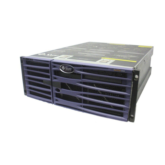
Page 14: Locating Front Panel Features
The system is configured with two power supplies and up to four disk drives, which are accessible from the front of the system. Sun Fire V440 Server Parts Installation and Removal Guide • July 2003... - Page 15 Front Panel LEDs Several front panel LEDs provide general system status, alert you to system problems, and help you to determine the location of system faults. During system startup, the LEDs are toggled on and off to verify that each one is working correctly.
- Page 16 LEDs on the front panel to determine the nature of the fault. See the Sun Fire V440 Server Diagnostics and Troubleshooting Guide for more information. System This green LED lights continuously when the system power is Activity Sun Fire V440 Server Parts Installation and Removal Guide • July 2003...
- Page 17 Disk Drive Status LEDs Each disk drive has its own status LEDs. Internal disk bays Disk drive LEDs Listed from top to bottom, the disk drive LEDs operate as described in the following table. Disk Drive LEDs TABLE 1-2 Icon Name Description OK-to-...
- Page 18 This green LED is lit when AC input power is present. This Available LED is lit when the corresponding AC cable is plugged into a power source and the power supply is functioning correctly, regardless of system power status. Sun Fire V440 Server Parts Installation and Removal Guide • July 2003...
- Page 19 Power Button The system Power button is recessed to prevent accidentally turning the system on or off. The ability of the Power button to turn the system on or off is controlled by the system control keyswitch. If the operating system is running, pressing and releasing the Power button initiates a graceful software system shutdown.
- Page 20 The Standby setting also prevents an ALOM console from restarting the system. However, the ALOM card continues to operate using the system’s standby power. Sun Fire V440 Server Parts Installation and Removal Guide • July 2003...
-
Page 21: Locating Back Panel Features
Locating Back Panel Features The illustration below shows the system features that are accessible from the back panel. Slot 5 Slot 4 Slot 3 System status LEDs Slot 2 Slot 1 Slot 0 Power supply status LEDs Power supply 1 AC inlet Power supply 0 AC inlet... - Page 22 Speed This amber LED lights when a Gigabit Ethernet connection is established, and is off when a 10/100-Mbps Ethernet connection is establshed. Sun Fire V440 Server Parts Installation and Removal Guide • July 2003...
- Page 23 Power Supply LEDs Each power supply has a corresponding set of four LEDs on the back panel. These LEDs operate as described in TABLE 1-3 Power supply 1 LEDs Power supply 0 LEDs Network Management Port LED The network management port has a Link LED that operates as described in TABLE 1-6 Network management port Network Management Port LED...
- Page 24 Out Manager (ALOM) card ports. PCI Slots The Sun Fire V440 server has three 33-MHz PCI slots and three 66-MHz PCI slots. These are labeled on the back panel. The Advanced Lights Out Manager (ALOM) card is located to the left of the PCI slots.
- Page 25 External Ports The Sun Fire V440 server has eight external data ports on the back panel, which are described in TABLE 1-7 USB (4) SCSI Serial Ethernet (ttyb) (net0, net1) Back Panel External Ports TABLE 1-7 Icon Description Serial port. The system has one serial port (ttyb) on the back panel, which uses a DB-9 connector.
- Page 26 Ethernet port. This port provides direct network access to the ALOM card, when configured, and can access the ALOM prompt and system console output. Sun Fire V440 Server Parts Installation and Removal Guide • July 2003...
-
Page 27: Locating Internal Components
Locating Internal Components The illustration below shows the system’s internal components from the top view. Crossbar DVD-ROM drive CPU/memory module 0 CPU fan tray (Fan tray 1) SCC reader Motherboard Front panel Back panel SC slot PCI slots Connector board PCI fan tray (Fan tray 0) SCSI backplane... - Page 28 Sun Fire V440 Server Parts Installation and Removal Guide • July 2003...
-
Page 29: Preparing To Service The System
C H A P T E R Preparing to Service the System This chapter contains the following sections: “Service Guidelines” on page 18 “Tools Required for Installation and Service” on page 18 “How to Power On the System” on page 19 “How to Power Off the System”... -
Page 30: Service Guidelines
Screwdriver, long Phillips No. 2 (shaft at least 8 inches/120.32 cm long) Adjustable wrench Electrostatic discharge (ESD) mat, Sun part number 250-1088, or equivalent Grounding wrist or foot strap Sun Fire V440 Server Parts Installation and Removal Guide • July 2003... -
Page 31: How To Power On The System
If you are powering on the system for the first time, connect a device to the serial management port using one of the methods described in the Sun Fire V440 Server Administration Guide. Otherwise, use one of the methods for connecting to the system... - Page 32 5. Insert the system key into the system control keyswitch and turn it to the Normal or Diagnostics position. See “System Control Keyswitch” on page 7 for information about each system control keyswitch setting. Sun Fire V440 Server Parts Installation and Removal Guide • July 2003...
- Page 33 Power button Normal position Diagnostics position 6. Press the Power button that is to the left of the system control keyswitch to power on the system. Output is immediately displayed to the system console if diagnostics are enabled at power-on, and the system console is directed to the serial and network management ports.
- Page 34 If desired, you can close and lock the system doors while the mini-key remains in the system control keyswitch. What Next To power off the system, complete this task: “How to Power Off the System” on page 23 Sun Fire V440 Server Parts Installation and Removal Guide • July 2003...
-
Page 35: How To Power Off The System
How to Power Off the System Before You Begin Caution – Applications running on the Solaris operating environment can be adversely affected by a poorly executed system shutdown. Ensure that you have gracefully shut down any applications before powering off the system. What to Do 1. - Page 36 Whenever possible, you should use the graceful software shutdown method. Forcing an immediate hardware shutdown can cause disk drive corruption and loss of data. Use that method only as a last resort. Sun Fire V440 Server Parts Installation and Removal Guide • July 2003...
- Page 37 6. Turn the system control keyswitch to the Standby position. Standby position Caution – Be sure to turn the system control keyswitch to the Standby position before handling any internal components. Otherwise, it is possible for an operator at an ALOM console to restart the system while you are working inside it. The Standby position is the only system control keyswitch position that prevents an ALOM user from restarting the system.
-
Page 38: How To Initiate A Reconfiguration Boot
Read the documentation supplied with the device for specific instructions. 2. Turn on power to the alphanumeric terminal or local graphics monitor, or log in to the ALOM system controller. Sun Fire V440 Server Parts Installation and Removal Guide • July 2003... - Page 39 The initializing memory messages appear after the system banner is displayed. The system banner contains the Ethernet address and the host ID. Sun Fire V440, No Keyboard Copyright 1998-2003 Sun Microsystems, Inc. All rights reserved.
- Page 40 Diagnostics position and power cycle the system. For information about system diagnostics and troubleshooting, see: Sun Fire V440 Server Diagnostics and Troubleshooting Guide Sun Fire V440 Server Parts Installation and Removal Guide • July 2003...
-
Page 41: How To Slide The System Out Of The Cabinet
How to Slide the System Out of the Cabinet This procedure describes placing the system in position for service by sliding it out of the cabinet without removing it from the rack. All service procedures can be performed while the system is still attached to the rack. Note –... - Page 42 Use a Phillips No. 2 screwdriver to loosen the captive screws, which are in recessed access holes in the decorative panels affixed to the system’s front panel. Sun Fire V440 Server Parts Installation and Removal Guide • July 2003...
- Page 43 6. Slide the system evenly out of the cabinet until the inner glides stop in the slide. Grasp the system’s front bezel and pull the system smoothly out of the cabinet. Continue pulling the system until the back of the chassis clears the cabinet and you hear the flat spring catches in the glides engage with an audible clicking sound.
-
Page 44: How To Slide The System Into The Cabinet
Press in on both spring catches to free the system glides. One flat spring catch is attached to each inner glide on the system. 2. Slide the system evenly into the cabinet until the system stops moving. Sun Fire V440 Server Parts Installation and Removal Guide • July 2003... - Page 45 3. Tighten the four captive screws that secure the system to the left and right vertical rails at the front of the cabinet. Use a Phillips No. 2 screwdriver to tighten the four captive screws, which are in recessed access holes in the decorative panels affixed to the system’s front panel. 4.
-
Page 46: How To Remove The Top Cover
3. Pull the latches up to release the top cover from the chassis, then lift the cover up and off the chassis. What Next To replace the top cover, see: “How to Install the Top Cover” on page 35 Sun Fire V440 Server Parts Installation and Removal Guide • July 2003... -
Page 47: How To Install The Top Cover
How to Install the Top Cover Before You Begin Complete this task: “How to Remove the Top Cover” on page 34 What to Do 1. Insert the back edge of the top cover under the lip on the back panel. 2. -
Page 48: How To Remove The System From The Cabinet
Open and remove the cabinet front door and back door. Caution – When completing a two-person procedure, always communicate your intentions clearly before, during, and after each step to minimize confusion. Sun Fire V440 Server Parts Installation and Removal Guide • July 2003... - Page 49 What to Do 1. Disconnect all external cables from the back panel of the system. Note each cable’s origin and its terminating connection. 2. Disconnect the cable management arm from the system, if applicable. 3. Extend the cabinet’s anti-tip legs. Caution –...
- Page 50 Catch 9. Set the system on a workbench or other stable surface. Sun Fire V440 Server Parts Installation and Removal Guide • July 2003...
-
Page 51: How To Install The System Into The Cabinet
This procedure assumes that the slide assemblies are already installed in the cabinet. For information about installing the slide assemblies, see: Sun Fire V440 Server Installation Guide Caution – The system is heavy. Two persons are required to install the system into the cabinet. - Page 52 2. Align the rounded ends of the inner glides on the system with the slide assemblies in the cabinet. Note – Make sure that the inner glides attached to the system are inserted within the ball-bearing runners. Sun Fire V440 Server Parts Installation and Removal Guide • July 2003...
- Page 53 3. Holding the system level, slide it evenly all the way into the cabinet until the inner glides stop. Tip – Slide the server in and out of the cabinet slowly and carefully to ensure that the slide assemblies are working correctly and are free from obstructions. Chapter 2 Preparing to Service the System...
- Page 54 4. Press the catch on each inner glide in order to slide the server all the way back into the cabinet. Catch 5. Slide the system evenly into the cabinet until the system stops moving. Sun Fire V440 Server Parts Installation and Removal Guide • July 2003...
- Page 55 6. Secure the system to the front rails using four M4, M6, or 10-32 screws, depending on your cabinet, to attach the chassis brackets to the rack. 7. Attach the cable management arm to the system, if applicable. Route the cables through the cable management arm. 8.
-
Page 56: How To Avoid Electrostatic Discharge
1. Disconnect the AC power cords only when performing the following procedures: Removing and replacing the motherboard Removing and replacing the SCSI backplane Removing and replacing the system configuration card reader Removing and replacing the keyswitch Sun Fire V440 Server Parts Installation and Removal Guide • July 2003... - Page 57 Removing and replacing the connector board Removing and replacing the Advanced Lights Out Manager (ALOM) card The AC power cords provide a discharge path for static electricity, so they should remain plugged in except when you are servicing the parts noted above. 2.
- Page 58 What Next To reassemble the system, see: “How to Install the Top Cover” on page 35 Sun Fire V440 Server Parts Installation and Removal Guide • July 2003...
-
Page 59: Servicing The Front Panel Removable Devices
C H A P T E R Servicing the Front Panel Removable Devices This chapter contains the following sections: “About Hot-Pluggable Components” on page 48 “How to Remove a Power Supply” on page 48 “How to Install a Power Supply” on page 51 “How to Remove a Power Supply Using the Hot-Plug Operation”... -
Page 60: About Hot-Pluggable Components
About Hot-Pluggable Components In a Sun Fire V440 server, the SCSI hard disk drives and power supplies are hot- pluggable components. No other component of the system is hot-pluggable. Hot- pluggable components are those that you can install or remove while the system is running, without affecting the rest of the system’s capabilities. - Page 61 OK-to-Remove LED is lit on the power supply you want to remove. For more information, see “Power Supply LEDs” on page 11 and the Sun Fire V440 Server Administration Guide. Power supply 0 LEDs...
- Page 62 AC power. Doing so could result in serious personal injury. What Next To reassemble the system, complete this task: “How to Install a Power Supply” on page 51 Sun Fire V440 Server Parts Installation and Removal Guide • July 2003...
-
Page 63: How To Install A Power Supply
How to Install a Power Supply Before You Begin Complete this task: “How to Remove a Power Supply” on page 48 What to Do 1. Make sure that the Phillips No. 2 captive screw on the new power supply is completely unlocked. -
Page 64: How To Remove A Power Supply Using The Hot-Plug Operation
The following procedure assumes that you are accessing the system console by the default method of connecting to the serial management port (SERIAL MGT) of the Sun Fire V440 server. Sun Fire V440 Server Parts Installation and Removal Guide • July 2003... - Page 65 2. Identify the power supply to be removed. Check the power supply LEDs to determine which power supply is faulty. For more information, see “Power Supply LEDs” on page 11 and the Sun Fire V440 Server Administration Guide. Power supply 0 LEDs...
- Page 66 Follow Step 3 and Step 4 of “How to Remove a Power Supply” on page 48. The system console displays a message confirming the removal of the power supply. Sun Fire V440 Server Parts Installation and Removal Guide • July 2003...
-
Page 67: How To Install A Power Supply Using The Hot-Plug Operation
The following procedure assumes that you are accessing the system console by the default method of connecting to the serial management port (SERIAL MGT) of the Sun Fire V440 server. Before You Begin Note – You have limited time to perform a power supply hot-plug operation. You have 10 minutes at sea level and a maximum of 7 minutes at 10,000 feet (3048 meters) to ensure proper system cooling. - Page 68 For more information about the power supply LEDs, see: “Power Supply LEDs” on page 6 To reassemble the system, close and lock the system doors. Sun Fire V440 Server Parts Installation and Removal Guide • July 2003...
-
Page 69: How To Remove A Disk Drive
1. Unlock and open the system doors. 2. Identify the disk drive to be removed and note the bay in which it is installed. See the Sun Fire V440 Server Diagnostics and Troubleshooting Guide for more information about isolating failed parts. - Page 70 3. Pinch the disk drive latch sideways to release the disk drive handle. 4. Pull the handle away from the disk drive until you feel the disk drive connector disengage from the SCSI backplane connector. Sun Fire V440 Server Parts Installation and Removal Guide • July 2003...
- Page 71 5. Holding the disk drive by the handle, slide the disk drive out of the disk drive bay. Note – When you reinstall the disk drive (or a replacement drive), be sure to install the disk drive into the same drive bay as the one from which it was just removed. 6.
-
Page 72: How To Install A Disk Drive
Note – If you are replacing a drive that you removed previously, be sure to install the disk drive into the same drive bay from which it was removed. Sun Fire V440 Server Parts Installation and Removal Guide • July 2003... - Page 73 4. Insert the disk drive into the disk drive bay guide rails. Slide the disk drive into the bay until it barely contacts the backplane. 5. Firmly press the center of the disk drive handle toward the disk drive until the latch closes, securing the disk drive in place.
-
Page 74: How To Remove A Disk Drive Using The Hot-Plug Operation
Use the cfgadm command to remove a Sun Fire V440 server’s internal disk drive using the hot-plug operation. The following procedure describes the general steps involved, but your specific device names might be different. - Page 75 Complete these tasks: Obtain the logical device name(s) for the device(s) you plan to remove. See the Sun Fire V440 Server Administration Guide for more information. Select the disk and stop any activity or applications accessing the disk drive. Unmount any file systems mounted on the disk drive.
-
Page 76: How To Install A Disk Drive Using The Hot-Plug Operation
Finally, you configure your application (if necessary) to operate with this new drive. Use the cfgadm command to install a Sun Fire V440 server’s internal disk drives using the hot-plug operation. The following procedure describes the general steps involved, but your specific device names might be different. - Page 77 What to Do 1. Insert the disk drive into its bay. Follow Step 1 through Step 6 of “How to Install a Disk Drive” on page 60. 2. Log in as superuser or root user: % su Password: 3. Configure the new disk drive using this command: # cfgadm -x configure /dev/rdsk/c0t0d0 where c0t0d0 is the name of the disk drive to be configured.
- Page 78 Sun Fire V440 Server Parts Installation and Removal Guide • July 2003...
-
Page 79: Servicing The Fans
C H A P T E R Servicing the Fans This chapter contains the following sections: “How to Remove the PCI Fan Tray” on page 67 “How to Install the PCI Fan Tray” on page 70 “How to Remove the CPU Fan Tray” on page 73 “How to Install the CPU Fan Tray”... - Page 80 See “How to Remove a PCI Card” on page 93. 2. Loosen the two Phillips No. 2 captive screws securing the crossbar to the chassis. 3. Remove the crossbar from the chassis and set it aside. Sun Fire V440 Server Parts Installation and Removal Guide • July 2003...
- Page 81 4. Disconnect the PCI fan tray cable at P7 on the connector board. 5. Pull the PCI fan tray up and out of the system. Make sure to guide the side tab on the fan tray through the notch in the side of the chassis.
-
Page 82: How To Install The Pci Fan Tray
The side tab fits into a slot in the chassis side. The two bottom tabs correspond to two slots in the bottom of the chassis. Side tab Bottom tabs Sun Fire V440 Server Parts Installation and Removal Guide • July 2003... - Page 83 2. Insert the PCI fan tray into the system until it is firmly seated. Note – Make sure that you align the card guides on the PCI fan tray with any long PCI cards in the system. 3. Connect the PCI fan tray cable at P7 on the connector board. Chapter 4 Servicing the Fans...
- Page 84 “How to Install the Top Cover” on page 35 “How to Slide the System Into the Cabinet” on page 32 “How to Power On the System” on page 19 Sun Fire V440 Server Parts Installation and Removal Guide • July 2003...
-
Page 85: How To Remove The Cpu Fan Tray
How to Remove the CPU Fan Tray Caution – Do not attempt to operate the system without the CPU fan tray (fan tray 1) installed. Doing so could overheat and seriously damage the system. Before You Begin If the CPU fan tray (fan tray 1) fails, the system Service Required LED will light. Complete these tasks: “How to Power Off the System”... - Page 86 7. Pull the CPU fan tray up and out of the system at an angle, lifting the side near the PCI fan tray first. What Next Complete this task: “How to Install the CPU Fan Tray” on page 75 Sun Fire V440 Server Parts Installation and Removal Guide • July 2003...
-
Page 87: How To Install The Cpu Fan Tray
How to Install the CPU Fan Tray Caution – Do not power on the system without a functioning CPU fan tray (fan tray 1) installed. Doing so could overheat and seriously damage the system. Before You Begin Complete this task: “How to Remove the CPU Fan Tray”... - Page 88 4. Connect the CPU fan tray cable at P8 on the connector board. Cable bracket 5. Tuck the cable into the cable bracket on the side of the SCSI backplane. Sun Fire V440 Server Parts Installation and Removal Guide • July 2003...
- Page 89 6. Mount the crossbar onto the chassis. Make sure that the tab on the crossbar inserts into the slot on top of the PCI fan tray. 7. Tighten the two Phillips No. 2 captive screws that secure the crossbar to the chassis.
- Page 90 Sun Fire V440 Server Parts Installation and Removal Guide • July 2003...
-
Page 91: Servicing The Motherboard Components
C H A P T E R Servicing the Motherboard Components This chapter contains the following sections: “How to Remove a CPU/Memory Module” on page 80 “How to Install a CPU/Memory Module” on page 83 “About the Memory Modules” on page 86 “How to Remove a Memory Module”... -
Page 92: How To Remove A Cpu/Memory Module
“How to Remove the Top Cover” on page 34 What to Do 1. Identify the CPU/memory module to be removed. See the Sun Fire V440 Server Diagnostics and Troubleshooting Guide for information about isolating failed parts. Sun Fire V440 Server Parts Installation and Removal Guide • July 2003... - Page 93 2. Loosen the two Phillips No. 2 captive screws securing the CPU/memory module to the CPU cage. CPU 0 CPU 1 CPU 2 CPU 3 Chapter 5 Servicing the Motherboard Components...
- Page 94 Support the CPU/memory module from underneath as you transfer it to the antistatic mat. Caution – The CPU/memory module can be hot. Handle the CPU/memory module carefully to avoid injury. Sun Fire V440 Server Parts Installation and Removal Guide • July 2003...
-
Page 95: How To Install A Cpu/Memory Module
What Next To replace the CPU/memory module, complete this task: “How to Install a CPU/Memory Module” on page 83 How to Install a CPU/Memory Module Before You Begin Complete these tasks: “How to Avoid Electrostatic Discharge” on page 44 “How to Remove a CPU/Memory Module” on page 80 What to Do 1. - Page 96 5. Push down on both ejector levers, simultaneously, until the levers are completely pressed into their slots. Note – Do not press down directly on the CPU/memory module. Let the levers press the CPU/memory module into its socket. Sun Fire V440 Server Parts Installation and Removal Guide • July 2003...
- Page 97 6. Tighten the two Phillips No. 2 captive screws that secure the CPU/memory module to the CPU cage. What Next To reassemble the system, complete these tasks: “How to Install the Top Cover” on page 35 “How to Slide the System Into the Cabinet” on page 32 “How to Power On the System”...
-
Page 98: About The Memory Modules
The system reads from, or writes to, both DIMMs in a group simultaneously. DIMMs, therefore, must be added in pairs. The figure below shows the DIMM slots and DIMM groups on a Sun Fire V440 server CPU/memory module. Adjacent slots belong to the same DIMM group. - Page 99 Memory Interleaving You can maximize the system’s memory bandwidth by taking advantage of its memory interleaving capabilities. The Sun Fire V440 server supports two-way interleaving. In most cases, higher interleaving results in improved system performance. However, actual performance results can vary depending on the system application.
-
Page 100: How To Remove A Memory Module
CPU/memory module and the DIMMs carefully to avoid injury. 1. Identify the memory module to be removed. See the Sun Fire V440 Server Diagnostics and Troubleshooting Guide for information about isolating failed parts. Sun Fire V440 Server Parts Installation and Removal Guide • July 2003... - Page 101 2. Push down on the ejector levers on each side of the memory module, simultaneously, until the memory module ejects from its socket. Apply even pressure on both levers. Chapter 5 Servicing the Motherboard Components...
-
Page 102: How To Install A Memory Module
Read the section: “About the Memory Modules” on page 86 Complete these tasks: “How to Avoid Electrostatic Discharge” on page 44 “How to Remove a CPU/Memory Module” on page 80 Sun Fire V440 Server Parts Installation and Removal Guide • July 2003... - Page 103 What to Do Caution – DIMMs are made of electronic components that are extremely sensitive to static electricity. Static electricity from your clothes or work environment can destroy the DIMM. Do not remove a DIMM from its antistatic packaging until you are ready to install it on the CPU/memory module.
- Page 104 5. Repeat Step 1 through Step 4 for all memory modules to be installed. What Next To reassemble the system, complete this task: “How to Install a CPU/Memory Module” on page 83 Sun Fire V440 Server Parts Installation and Removal Guide • July 2003...
-
Page 105: How To Remove A Pci Card
How to Remove a PCI Card Before You Begin Complete these tasks: “How to Power Off the System” on page 23 “How to Slide the System Out of the Cabinet” on page 29 “How to Avoid Electrostatic Discharge” on page 44 “How to Remove the Top Cover”... - Page 106 The PCI filler panel prevents debris from entering the system and ensures proper cooling. a. Slide the filler panel into the appropriate slot. b. Replace the Phillips No. 1 screw that secures the filler panel to the system back panel. Sun Fire V440 Server Parts Installation and Removal Guide • July 2003...
-
Page 107: How To Install A Pci Card
Note – Installing a 33-MHz PCI card into a 66-MHz slot (slots 2, 4, or 5) causes each card or device on that bus to operate at 33-MHz. For more information about PCI cards and buses, see the Sun Fire V440 Server Administration Guide. Chapter 5 Servicing the Motherboard Components... - Page 108 Caution – Do not apply excessive force to one end or one side of the card. Doing so could damage the card or the motherboard connector. 4. Secure the PCI card faceplate to the system back panel with the Phillips No. 1 screw. Sun Fire V440 Server Parts Installation and Removal Guide • July 2003...
-
Page 109: How To Remove The Alom Card
For additional information, see: Sun Fire V440 Server Administration Guide You must also perform a reconfiguration boot so that your system is able to recognize the new PCI card. For additional information, see: “How to Initiate a Reconfiguration Boot”... - Page 110 4. Remove the Phillips No. 1 screw securing the card to the system back panel. Caution – Make sure that the AC power cords are disconnected from the system before removing the ALOM card. Sun Fire V440 Server Parts Installation and Removal Guide • July 2003...
-
Page 111: How To Install The Alom Card
5. Pull the ALOM card from its slot. Hold the card by the faceplate and its opposite edge. Pull up while rocking the card from end to end until it is freed from its slot. 6. Place the ALOM card on an antistatic mat. What Next To replace the ALOM card, complete this task: “How to Install the ALOM Card”... - Page 112 “How to Install the Top Cover” on page 35 “How to Slide the System Into the Cabinet” on page 32 “How to Power On the System” on page 19 Sun Fire V440 Server Parts Installation and Removal Guide • July 2003...
-
Page 113: How To Remove The Motherboard
How to Remove the Motherboard Before You Begin Complete these tasks: “How to Power Off the System” on page 23 “How to Slide the System Out of the Cabinet” on page 29 “How to Avoid Electrostatic Discharge” on page 44 “How to Remove the Top Cover”... - Page 114 Loosen the Phillips No. 2 captive screw on the CPU fan tray. b. Slide fan tray 1 forward, over the DVD-ROM cable, as far as the hooks allow. Sun Fire V440 Server Parts Installation and Removal Guide • July 2003...
- Page 115 3. Disconnect the AC inlet assembly from the back of the chassis. a. Disconnect the P13 rear LED power cable end from its connector on the CPU side of the chassis. Lay the cable out of the way. b. Loosen the two Phillips No. 2 captive screws securing the AC inlet faceplate to the back of the chassis.
- Page 116 Note and label connector locations. b. Remove the three Phillips No. 2 screws securing the I/O faceplate to the chassis. Pull the faceplate off the system and set it aside. Sun Fire V440 Server Parts Installation and Removal Guide • July 2003...
- Page 117 5. Disconnect the P5 connector board power cable end at P5 on the motherboard. Press the locking tab on the cable end and pull it out of the connector. 6. Disconnect the P1 DVD-ROM cable end at P1 on the motherboard. Lift up the connector ejector levers as far as they go to release the DVD-ROM cable end from the connector, then pull the DVD-ROM cable out of the connector.
- Page 118 8. Loosen the ten Phillips No. 2 captive screws securing the motherboard to the chassis. Note – Make sure that you do not unscrew the captive screws completely. Loosen the captive screws until you feel resistance. Sun Fire V440 Server Parts Installation and Removal Guide • July 2003...
-
Page 119: How To Install The Motherboard
9. Remove the motherboard from the chassis. Remove the motherboard at an angle to clear the chassis sides. What Next Complete this task: “How to Install the Motherboard” on page 107 How to Install the Motherboard Before You Begin Complete this task: “How to Remove the Motherboard”... - Page 120 Place the post on the bottom of the motherboard into the hole in the chassis to properly align the motherboard. The post is located on the corner of the motherboard near the SCSI backplane. Post Sun Fire V440 Server Parts Installation and Removal Guide • July 2003...
- Page 121 2. Tighten the ten Phillips No. 2 captive screws to secure the motherboard to the chassis. Chapter 5 Servicing the Motherboard Components...
- Page 122 Push the cable end into its connector until the ejector levers lie flat. SCSI data cable DVD-ROM cable Connector board power cable 5. Connect the P5 connector board power cable end at P5 on the motherboard. Sun Fire V440 Server Parts Installation and Removal Guide • July 2003...
- Page 123 6. Install the AC inlet assembly. a. Place the AC inlet assembly into the system, aligning the faceplace with the chassis back panel. b. Secure the AC inlet assembly faceplate to the chassis with the two Phillips No. 2 captive screws. c.
- Page 124 Align the I/O faceplate on the back panel. b. Secure the faceplate to the chassis using three Phillips No. 2 screws. c. Connect any external cables, as needed. Sun Fire V440 Server Parts Installation and Removal Guide • July 2003...
- Page 125 8. Secure the CPU fan tray. a. Slide the CPU fan tray toward the back of the system until the hooks lock into place. b. Tighten the Phillips No. 2 captive screw that secures the CPU fan tray to the chassis.
- Page 126 “How to Install the Top Cover” on page 35 “How to Slide the System Into the Cabinet” on page 32 “How to Power On the System” on page 19 Sun Fire V440 Server Parts Installation and Removal Guide • July 2003...
-
Page 127: Servicing Miscellaneous Components
C H A P T E R Servicing Miscellaneous Components This chapter contains the following sections: “How to Remove the DVD-ROM Drive” on page 116 “How to Install the DVD-ROM Drive” on page 117 “How to Remove the System Configuration Card” on page 119 “How to Install the System Configuration Card”... -
Page 128: How To Remove The Dvd-Rom Drive
“How to Remove the Top Cover” on page 34 What to Do 1. Press down on the two DVD-ROM drive locking tabs, releasing the DVD-ROM drive from its cage. Sun Fire V440 Server Parts Installation and Removal Guide • July 2003... -
Page 129: How To Install The Dvd-Rom Drive
2. Pull out the DVD-ROM drive from the front of the system. What Next Complete this task: “How to Install the DVD-ROM Drive” on page 117 How to Install the DVD-ROM Drive Before You Begin Complete this task: “How to Remove the DVD-ROM Drive” on page 116 Chapter 6 Servicing Miscellaneous Components... - Page 130 “How to Install the Top Cover” on page 35 “How to Slide the System Into the Cabinet” on page 32 “How to Power On the System” on page 19 Sun Fire V440 Server Parts Installation and Removal Guide • July 2003...
-
Page 131: How To Remove The System Configuration Card
This section explains how to remove a system configuration card (SCC). The SCC stores system configuration variables and MAC addresses. For more information, see “About the System Configuration Card” in the Sun Fire V440 Server Administration Guide. You can replace a functioning SCC and install it into another system thereby preserving the system’s host ID information. -
Page 132: How To Install The System Configuration Card
“How to Install the System Configuration Card” on page 120 How to Install the System Configuration Card Before You Begin Complete this task: “How to Remove the System Configuration Card” on page 119 Sun Fire V440 Server Parts Installation and Removal Guide • July 2003... - Page 133 What to Do 1. Insert the SCC into the SCC reader, which is at the left of the Power button. Orient the SCC so that the Sun logo is on the top of the card. 2. Insert the security post into its position in front of the SCC. What Next Complete this task: “How to Power On the System”...
-
Page 134: How To Remove The System Configuration Card Reader
To avoid personal injury or damage to the system, you must disconnect the AC power cords before servicing the system configuration card reader. 1. Disconnect the AC power cords from the back of the system. Sun Fire V440 Server Parts Installation and Removal Guide • July 2003... - Page 135 2. Disconnect the cables from the system configuration card (SCC) reader. a. Disconnect the connector board power cable at J18. Pull up on the cable end to release it from its connector. b. Disconnect the system control keyswitch cable at J2. Press the tab on the cable end to release it from its connector.
-
Page 136: How To Install The System Configuration Card Reader
To avoid personal injury or damage to the system, you must disconnect the AC power cords before servicing the system configuration card reader. 1. Disconnect the AC power cords from the back of the system. Sun Fire V440 Server Parts Installation and Removal Guide • July 2003... - Page 137 2. Insert the SCC reader into the system. a. Insert the Power button through its hole in the chassis. b. Align the holes in the SCC reader with the corresponding mounting posts on the chassis. 3. Snap the SCC reader into place. Press down on the front corners, then on the back corners of the SCC reader.
-
Page 138: How To Remove The Connector Board
To avoid personal injury or damage to the system, you must disconnect the AC power cords before servicing the connector board. 1. Disconnect the AC power cords from the back of the system. Sun Fire V440 Server Parts Installation and Removal Guide • July 2003... - Page 139 2. Disconnect the five cables from the connector board. Connector board power PCI fan tray cable at P6 cable at P7 Front LED cable at P15 SCC reader cable at P19 CPU fan tray cable at P8 Screw 3. Loosen the Phillips No. 2 captive screw securing the connector board to the chassis.
-
Page 140: How To Install The Connector Board
3. Slide the connector board toward the back of the system to connect the board to the SCSI backplane. The connector board clicks into place. 4. Secure the connector board to the chassis with the Phillips No. 2 captive screw. Sun Fire V440 Server Parts Installation and Removal Guide • July 2003... - Page 141 5. Connect the five cables to the connector board. Insert the cable ends into the appropriate connectors. Each connector is unique and matches only one cable end. Connector board power PCI fan tray cable at P6 cable at P7 Front LED cable at P15 SCC reader cable at P19...
-
Page 142: How To Remove The Scsi Backplane
3. Loosen the Phillips No. 2 captive screw securing the connector board to the chassis. 4. Disengage the connector board from the SCSI backplane. Pull the connector board forward until it is disconnected from the SCSI backplane. Sun Fire V440 Server Parts Installation and Removal Guide • July 2003... - Page 143 5. Loosen the two Phillips No. 2 captive screws securing the SCSI backplane to the chassis. 6. Disconnect the P4 SCSI data cable end from the SCSI backplane. Pull the cable end out of its connector. Chapter 6 Servicing Miscellaneous Components...
- Page 144 7. Pull the SCSI backplane up and out of the system. What Next Complete this task: “How to Install the SCSI Backplane” on page 133 Sun Fire V440 Server Parts Installation and Removal Guide • July 2003...
-
Page 145: How To Install The Scsi Backplane
How to Install the SCSI Backplane Before You Begin Complete this task: “How to Remove the SCSI Backplane” on page 130 What to Do Caution – The system supplies power to the SCSI backplane even when the system is powered off. To avoid personal injury or damage to the system, you must disconnect the AC power cords before servicing the SCSI backplane. - Page 146 Make sure that the connector board does not come in contact with the SCSI backplane at this point in the installation. 4. Tighten the two Phillips No. 2 captive screws that secure the SCSI backplane to the chassis. Sun Fire V440 Server Parts Installation and Removal Guide • July 2003...
- Page 147 5. Slide the connector board toward the back of the system to connect the board to the SCSI backplane. Push the connector board into the SCSI backplane until it is secure. 6. Tighten the Phillips No. 2 captive screw to secure the connector board to the chassis.
- Page 148 Sun Fire V440 Server Parts Installation and Removal Guide • July 2003...
-
Page 149: Servicing Cables
C H A P T E R Servicing Cables This chapter contains the following sections: “Cable Connections and Routing” on page 138 “How to Remove the SCC Reader Cable” on page 139 “How to Install the SCC Reader Cable” on page 141 “How to Remove the SCSI Data Cable”... -
Page 150: Cable Connections And Routing
SCSI backplane at P4 (530-2144) DVD-ROM Cable Motherboard at P1 DVD-ROM drive at J1 Route across power supply bays, down the side of power (375-3104) supply bay 0. Sun Fire V440 Server Parts Installation and Removal Guide • July 2003... -
Page 151: How To Remove The Scc Reader Cable
How to Remove the SCC Reader Cable Before You Begin Complete these tasks: “How to Power Off the System” on page 23 “How to Slide the System Out of the Cabinet” on page 29 “How to Avoid Electrostatic Discharge” on page 44 “How to Remove the Top Cover”... - Page 152 3. Disconnect the SCC reader cable end at J18 on the SCC reader. Pull the cable end off its connector. What Next Complete this task: “How to Install the SCC Reader Cable” on page 141 Sun Fire V440 Server Parts Installation and Removal Guide • July 2003...
-
Page 153: How To Install The Scc Reader Cable
How to Install the SCC Reader Cable Before You Begin Complete this task: “How to Remove the SCC Reader Cable” on page 139 What to Do Caution – The system supplies power to the system configuration card reader cable even when the system is powered off. To avoid personal injury or damage to the system, you must disconnect the AC power cords before servicing the system configuration card reader cable. -
Page 154: How To Remove The System Control Keyswitch Cable
To avoid personal injury or damage to the system, you must disconnect the AC power cords before servicing the system control keyswitch cable. 1. Disconnect the AC power cords from the back of the system. Sun Fire V440 Server Parts Installation and Removal Guide • July 2003... - Page 155 2. Disconnect the system control keyswitch cable end at J2 on the SCC reader. Press the locking tab on the cable end and pull it off its connector. 3. Disconnect the system control keyswitch cable from the keyswitch faceplate. Pull the cable end gently off the keyswitch faceplate. What Next Complete this task: “How to Install the System Control Keyswitch Cable”...
-
Page 156: How To Install The System Control Keyswitch Cable
AC power cords before servicing the system control keyswitch cable. 1. Connect the system control keyswitch cable end to the keyswitch faceplate. Press the cable end into the keyswitch faceplate. Sun Fire V440 Server Parts Installation and Removal Guide • July 2003... - Page 157 2. Connect the J2 system control keyswitch cable end at J2 on the SCC reader. Press the cable end into its connector. 3. Connect the AC power cords to the back of the system. What Next Complete these tasks: “How to Install the Top Cover” on page 35 “How to Slide the System Into the Cabinet”...
-
Page 158: How To Remove The Connector Board Power Cable
To avoid personal injury or damage to the system, you must disconnect the AC power cords before servicing the connector board power cable. 1. Disconnect the AC power cords from the back of the system. Sun Fire V440 Server Parts Installation and Removal Guide • July 2003... - Page 159 2. Disconnect the P5 cable end at P5 on the motherboard. Press the locking tab on the cable end and pull the cable out of its connector. 3. Disconnect the P6 cable end at P6 on the connector board. Press the locking tab on the cable end and pull the cable out of its connector. Connector board power cable What Next Complete this task:...
-
Page 160: How To Install The Connector Board Power Cable
AC power cords before servicing the connector board power cable. 1. Connect the P6 cable end at P6 on the connector board. 2. Connect the P5 cable end at P5 on the motherboard. Sun Fire V440 Server Parts Installation and Removal Guide • July 2003... - Page 161 3. Connect the AC power cords to the back of the system. Connector board power cable What Next Complete these tasks: “How to Install the Top Cover” on page 35 “How to Slide the System Into the Cabinet” on page 32 “How to Power On the System”...
-
Page 162: How To Remove The Scsi Data Cable
Pull the cable end out of its connector. 2. Disconnect the P4 cable end at P4 on the SCSI backplane. Pull the cable end out of its connector. Sun Fire V440 Server Parts Installation and Removal Guide • July 2003... -
Page 163: How To Install The Scsi Data Cable
What Next Complete this task: “How to Install the SCSI Data Cable” on page 151 How to Install the SCSI Data Cable Before You Begin Complete this task: “How to Remove the SCSI Data Cable” on page 150 What to Do 1. -
Page 164: How To Remove The Dvd-Rom Cable
What to Do 1. Disconnect the P1 cable end at P1 on the motherboard. Lift the locking levers on the sides of the connector to release the cable end. Sun Fire V440 Server Parts Installation and Removal Guide • July 2003... - Page 165 2. Using a Phillips No. 1 screwdriver, remove the two screws securing the DVD-ROM cable end to the DVD-ROM drive. What Next Complete this task: “How to Install the DVD-ROM Cable” on page 154 Chapter 7 Servicing Cables...
-
Page 166: How To Install The Dvd-Rom Cable
0. Tuck the cable under three metal tabs on top of the power supply bays and one tab on the side of power supply bay 0. Sun Fire V440 Server Parts Installation and Removal Guide • July 2003... - Page 167 3. Connect the P1 cable end at P1 on the motherboard. a. Make sure that the connector levers are rotated up before inserting the cable. b. Press the cable end into the connector until the connector levers lie flat. What Next Complete these tasks: “How to Install the PCI Fan Tray”...
- Page 168 Sun Fire V440 Server Parts Installation and Removal Guide • July 2003...
-
Page 169: Connector Pinouts
A P P E N D I X Connector Pinouts This appendix provides reference information about the system back panel ports and pin assignments. Topics covered in this appendix include: “Reference for the Serial Port Connector” on page 158 “Reference for the USB Connectors” on page 159 “Reference for the Gigabit Ethernet Connectors”... -
Page 170: Reference For The Serial Port Connector
Serial Port Connector Signals Signal Description Signal Description Data Carrier Detect Data Set Ready Receive Data Request to Send Transmit Data Clear to Send Data Terminal Ready Ring Indicate Ground Sun Fire V440 Server Parts Installation and Removal Guide • July 2003... -
Page 171: Reference For The Usb Connectors
Reference for the USB Connectors Four Universal Serial Bus (USB) ports are located on the motherboard in a double-stacked layout and can be accessed from the back panel. USB Connector Diagram USB3 USB2 USB1 USB0 USB Connector Signals Signal Description Signal Description +5 V (fused) +5 V (fused) -
Page 172: Reference For The Gigabit Ethernet Connectors
Transmit/Receive Data 2 – Transmit/Receive Data 0 – Transmit/Receive Data 1 – Transmit/Receive Data 1 + Transmit/Receive Data 3 + Transmit/Receive Data 2 + Transmit/Receive Data 3 – Sun Fire V440 Server Parts Installation and Removal Guide • July 2003... - Page 173 Reference for the Network Management Connector The network management connector (labeled NET MGT) is an RJ-45 connector located on the ALOM card and can be accessed from the back panel. This port needs to be configured prior to use. Network Management Connector Diagram NET MGT Network Management Connector Signals Signal Description...
- Page 174 Serial Management Connector Diagram Serial Management Connector Signals Signal Description Signal Description Request to Send Ground Data Terminal Ready Receive Data Transmit Data Data Set Ready Ground Clear to Send Sun Fire V440 Server Parts Installation and Removal Guide • July 2003...
- Page 175 Reference for the SCSI Connector The SCSI serial data connector is located on the motherboard and can be accessed from the back panel. SCSI Connector Diagram SCSI Connector Signals Signal Description Signal Description Data12 + Data12 – Data13 + Data13 – Data14 + Data14 –...
- Page 176 CD + CD – REQ + REQ – I/O + I/O – Data8 + Data8 – Data9 + Data9 – Data10 + Data10 – Data11 + Data11 – Sun Fire V440 Server Parts Installation and Removal Guide • July 2003...
- Page 177 A P P E N D I X System Specifications This appendix provides the following specifications for the Sun Fire V440 server: “Reference for Physical Specifications” on page 166 “Reference for Electrical Specifications” on page 166 “Reference for Environmental Specifications” on page 167 “Reference for Agency Compliance Specifications”...
- Page 178 * Refers to total input current required for both AC inlets when operating with dual power supplies or current required for a single AC inlet when operating with a single power supply. Sun Fire V440 Server Parts Installation and Removal Guide • July 2003...
- Page 179 Reference for Environmental Specifications The operating and non-operating environmental specifications for the system are as follows. Parameter Value Operating Temperature 5˚C to 40˚C (41˚F to 104˚F) noncondensing—IEC 60068-2-1&2 Humidity 20% to 80% RH noncondensing; 27˚C max wet bulb—IEC 60068-2- 3&56 Altitude 0 to 3000 meters (0 to 10,000 feet)—IEC 60068-2-13 Vibration (random)
- Page 180 Access Specifications Minimum clearances needed for servicing the system are as follows. Blockage Required Clearance Front of System 36 in (91.4 cm) Back of System 36 in (91.4 cm) Sun Fire V440 Server Parts Installation and Removal Guide • July 2003...
- Page 181 A P P E N D I X Board Connector Locations This appendix illustrates the connector locations on the system boards. It contains the following sections: “Motherboard Connectors” on page 170 “SCSI Backplane Connectors” on page 171 “Connector Board Connectors” on page 171 “ALOM Card Connectors”...
-
Page 182: Motherboard Connectors
Serial connector (ttyb) 33-MHz PCI USB connectors slots (0, 1, and 3) Ethernet connectors SCSI external connector ALOM (system controller) slot 66-MHz PCI slots (2, 4, and 5) Sun Fire V440 Server Parts Installation and Removal Guide • July 2003... -
Page 183: Scsi Backplane Connectors
SCSI Backplane Connectors Connector board connector Disk drive connectors SCSI data connector Connector Board Connectors Connector board power connector Connects to SCSI backplane SCC cable connector CPU fan tray (fan tray 1) connector PCI fan tray (fan tray 0) connector Front panel LED connector Appendix C... -
Page 184: Alom Card Connectors
ALOM Card Connectors Serial management connector Network management connector SCC Reader Connectors SCC cable connector Keyswitch cable connector Sun Fire V440 Server Parts Installation and Removal Guide • July 2003... - Page 185 A P P E N D I X Illustrated Parts Breakdown This appendix contains a sequence of illustrations that show how the various pieces of the system fit together. Use the accompanying tables as a reference for ordering field-replaceable units (FRUs). The part numbers listed in the following tables are correct as of the manual publication date but are subject to change without notice.
- Page 186 330-3724-01 System configuration card F370-5155 System key (not shown) 240-4341-01 Decorative panel, right (not shown) 330-3592-01 (Not a FRU) Decorative panel, left (not shown) 330-3630-01 (Not a FRU) Sun Fire V440 Server Parts Installation and Removal Guide • July 2003...
- Page 187 Fan Components Reference Number Part Part Number PCI fan tray (Fan tray 0) F540-5258 CPU fan tray (Fan tray 1) F540-5383 Crossbar 340-7450-03 (Not a FRU) Top cover 340-6871-05 (Not a FRU) Appendix D Illustrated Parts Breakdown...
- Page 188 1.28 GHz CPU/memory module (not F501-6370 shown) 512 MB DIMM F370-4939 1 GB DIMM (not shown) F370-4940 ALOM card F501-6346 Motherboard F501-6344 Rear LED cable (not shown) 370-5576-02 (Not a FRU) Sun Fire V440 Server Parts Installation and Removal Guide • July 2003...
- Page 189 Miscellaneous Components Reference Number Part Part Number Top cover 340-6871-05 (Not a FRU) DVD-ROM drive F540-5596 SCC reader F370-5127 SCSI backplane F501-6335 Connector board F501-6384 Appendix D Illustrated Parts Breakdown...
- Page 190 TABLE 7-1 Part Part Number SCC reader cable 530-3151 System control keyswitch cable 530-3148 Connector board power cable 530-3145 SCSI data cable 530-3144 DVD-ROM cable 375-3104 Sun Fire V440 Server Parts Installation and Removal Guide • July 2003...
- Page 191 Index system configuration card (SCC) reader installing, 141 Advanced Lights Out Manager (ALOM) card removing, 139 connectors, 172 system control keyswitch installing, 99 installing, 144 removing, 97 removing, 142 agency compliance specifications, 168 clearance specifications, 168 connector board connectors, 171 installing, 128 removing, 126 booting, after installing new hardware, 26...
- Page 192 LEDs hot-plug operation, 52 disk drive status LEDs, 5 non-hot-plug operation, 48 power supply status LEDs, 6 power-on self-test (POST), 8 system status LEDs, 3 Sun Fire V440 Server Parts Installation and Removal Guide • July 2003...
- Page 193 reconfiguration boot, initiating, 26 safety agency compliance, 168 SCSI backplane connectors, 171 installing, 133 removing, 130 security lock, 2 serial management port (SERIAL MGT), 14 service access specifications, 168 specifications agency compliance, 168 clearance, 168 electrical, 166 environmental, 167 physical, 166 service access, 168 system configuration card (SCC) installing, 120...
- Page 194 Sun Fire V440 Server Parts Installation and Removal Guide • July 2003...
Need help?
Do you have a question about the Sun Fire V440 and is the answer not in the manual?
Questions and answers