Sun Microsystems Sun Fire V480 Administration Manual
Hide thumbs
Also See for Sun Fire V480:
- Parts installation and removal manual (240 pages) ,
- Setup and rackmounting manual (20 pages)
Table of Contents

Related Manuals for Sun Microsystems Sun Fire V480


Summary of Contents for Sun Microsystems Sun Fire V480
- Page 1 Sun Fire V480 Server ™ Administration Guide Sun Microsystems, Inc. 901 San Antonio Road Palo Alto, CA 94303-4900 U.S.A. 650-960-1300 Part No. 816-0904-10 February 2002 Revision A Send comments about this document to: docfeedback@sun.com...
- Page 2 Etats-Unis et dans d’autres pays et licenciée exclusivement par X/Open Company, Ltd. Sun, Sun Microsystems, le logo Sun, Sun Fire, Solaris, VIS, Sun StorEdge, Solstice DiskSuite, Java, SunVTS et le logo Solaris sont des marques de fabrique ou des marques déposées de Sun Microsystems, Inc. aux Etats-Unis et dans d’autres pays.
-
Page 3: Declaration Of Conformity
Declaration of Conformity Compliance Model Number: Cherrystone Product Family Name: Sun Fire V480 European Union This equipment complies with the following requirements of the EMC Directive 89/336/EEC: EN55022:1998/CISPR22:1997 Class A EN550024:1998 Required Limits (as applicable): EN61000-4-2 4 kV (Direct), 8 kV (Air) - Page 4 Sun Fire V480 Server Parts Installation and Removal Guide • February 2002...
-
Page 5: Regulatory Compliance Statements
FCC radio frequency emission limits. Networking connections can be made using unshielded twisted-pair (UTP) cables. Modifications: Any modifications made to this device that are not approved by Sun Microsystems, Inc. may void the authority granted to the user by the FCC to operate this equipment. - Page 6 ICES-003 Class B Notice - Avis NMB-003, Classe B This Class B digital apparatus complies with Canadian ICES-003. Cet appareil numérique de la classe B est conforme à la norme NMB-003 du Canada. Sun Fire V480 Server Administration Guide • February 2002...
-
Page 7: Bsmi Class A Notice
BSMI Class A Notice The following statement is applicable to products shipped to Taiwan and marked as Class A on the product compliance label. Regulatory Compliance Statements... - Page 8 Sun Fire V480 Server Administration Guide • February 2002...
-
Page 9: Table Of Contents
Part One – Installation 1 Sun Fire V480 Server Installation 3 About the Parts Shipped to You 4 How to Install the Sun Fire V480 Server 5 Part Two – Background 9 System Overview 11 About the Sun Fire V480 Server 12... - Page 10 About Hardware Jumpers 40 PCI Riser Board Jumpers 41 RSC Card Jumpers 42 About the Power Supplies 43 Configuration Rule 45 About the Fan Trays 45 Configuration Rule 46 About FC-AL Technology 47 Sun Fire V480 Server Administration Guide • February 2002...
- Page 11 About the FC-AL Backplane 48 Configuration Rules 49 About the HSSDC FC-AL Port 49 About the FC-AL Host Adapters 50 Configuration Rules 50 About the Internal Disk Drives 50 Configuration Rule 51 About the Serial Port 51 About the USB Ports 52 Network Interfaces and System Firmware 53 About the Network Interfaces 54 About Redundant Network Interfaces 55...
- Page 12 Hot Spares (Hot Relocation) 73 For More Information 74 About Sun Cluster Software 74 For More Information 74 About Communicating With the System 75 What the System Console Does 75 Using the System Console 76 Sun Fire V480 Server Administration Guide • February 2002...
- Page 13 Default System Console Configuration 76 Alternative System Console Configuration 76 Diagnostic Tools 79 About the Diagnostic Tools 80 About Diagnostics and the Boot Process 84 Stage One: OpenBoot Firmware and POST 84 What Are POST Diagnostics For? 85 What POST Diagnostics Do 86 What POST Error Messages Tell You 87 Controlling POST Diagnostics 88 Stage Two: OpenBoot Diagnostics Tests 90...
- Page 14 Reference for System Console OpenBoot Variable Settings 147 Configuring Network Interfaces and the Boot Device 149 How to Configure the Primary Network Interface 150 How to Configure Additional Network Interfaces 152 How to Select the Boot Device 155 Sun Fire V480 Server Administration Guide • February 2002...
- Page 15 Configuring System Firmware 159 How to Enable OpenBoot Environmental Monitoring 160 How to Disable OpenBoot Environmental Monitoring 160 How to Obtain OpenBoot Environmental Status Information 161 How to Enable the Watchdog Mechanism and Its Options 162 How to Enable ASR 163 How to Disable ASR 164 How to Obtain ASR Status Information 164 How to Redirect the System Console to RSC 165...
- Page 16 Reference for the RSC Serial Connector 219 RSC Serial Connector Diagram 219 RSC Serial Connector Signals 219 Reference for the FC-AL Port HSSDC Connector 220 HSSDC Connector Diagram 220 HSSDC Connector Signal 220 Sun Fire V480 Server Administration Guide • February 2002...
- Page 17 System Specifications 221 Reference for Physical Specifications 222 Reference for Electrical Specifications 222 Reference for Environmental Specifications 223 Reference for Agency Compliance Specifications 224 Reference for Clearance and Service Access Specifications 224 Safety Precautions 225 Index 235 Contents xvii...
- Page 18 Sun Fire V480 Server Administration Guide • February 2002...
- Page 19 FIGURE 3-7 Power Supply Locations 44 FIGURE 3-8 Fan Trays 46 FIGURE 3-9 Simplified Schematic View of a Sun Fire V480 System 82 FIGURE 6-1 Boot PROM and IDPROM 85 FIGURE 6-2 POST Diagnostic Running Across FRUs 88 FIGURE 6-3...
- Page 20 Sun Fire V480 Server Administration Guide • February 2002...
- Page 21 Tables System LEDs 17 TABLE 2-1 Fan Tray LEDs 17 TABLE 2-2 Hard Disk Drive LEDs 17 TABLE 2-3 System Control Switch Settings 19 TABLE 2-4 Ethernet LEDs 20 TABLE 2-5 Power Supply LEDs 21 TABLE 2-6 Association Between CPUs and DIMM Groups 34 TABLE 3-1 PCI Bus Characteristics, Associated Bridge Chips, Centerplane Devices, TABLE 3-2...
- Page 22 TABLE 7-2 Using Solaris Information Display Commands 203 TABLE 11-1 Using OpenBoot Information Commands 204 TABLE 11-2 Useful SunVTS Tests to Run on a Sun Fire V480 System 209 TABLE 12-1 xxii Sun Fire V480 Server Administration Guide • February 2002...
-
Page 23: Preface
Solaris™ operating environment. Before You Read This Book While the first part of this manual focuses on installation of the Sun Fire V480 server, it does not deal with mounting the server in a cabinet or 2-post rack. For those instructions, see the Sun Fire V480 Server Setup and Rackmounting Guide. - Page 24 Each part of the book is divided into chapters. Part One: Chapter 1 describes and provides instructions for Sun Fire V480 server installation. Part Two: Chapter 2 presents an illustrated overview of the server and a description of the server’s reliability, availability, and serviceability (RAS) features.
-
Page 25: Typographic Conventions
Using UNIX Commands ® This document might not contain information on basic UNIX commands and procedures such as shutting down the system, booting the system, and configuring devices. See one or more of the following for this information: Solaris Handbook for Sun Peripherals AnswerBook2™... -
Page 26: Related Documentation
Removal Guide Accessing Sun Documentation Online A broad selection of Sun system documentation is located at: http://www.sun.com/products-n-solutions/hardware/docs A complete set of Solaris documentation and many other titles are located at: http://docs.sun.com xxvi Sun Fire V480 Server Administration Guide • February 2002... -
Page 27: Sun Welcomes Your Comments
Sun Welcomes Your Comments Sun is interested in improving its documentation and welcomes your comments and suggestions. You can email your comments to Sun at: docfeedback@sun.com Please include the part number (816-0904-10) of your document in the subject line of your email. - Page 28 Sun Fire V480 Server Administration Guide • February 2002...
-
Page 29: Part One - Installation
For illustrated background information about the hardware and software components of the Sun Fire V480 server, see the chapters in Part Two – Background. For detailed instructions on how to configure and administer the server, and how to perform various diagnostic routines to resolve problems with the server, see the chapters in Part Three –... -
Page 31: Sun Fire V480 Server Installation
This chapter provides both an overview of, and instructions for, the hardware and software tasks you need to accomplish to get the Sun Fire V480 server up and running. This chapter explains some of what you need to do, and points you to the appropriate section in this manual, or to other manuals for more information. -
Page 32: About The Parts Shipped To You
About the Parts Shipped to You Standard features for Sun Fire V480 systems are installed at the factory. However, if you ordered options such as a monitor, these will be shipped to you separately. In addition, you should have received the media and documentation for all appropriate system software. -
Page 33: How To Install The Sun Fire V480 Server
Each step in this procedure refers you to a particular document or to a section of this guide for instructions. Complete each step in the order listed. The best way to begin your installation of a Sun Fire V480 server is by completing the rackmounting and setup procedures in the Sun Fire V480 Server Setup and Rackmounting Guide. -
Page 34: What To Do
What to Do If you have completed the procedures in the Sun Fire V480 Server Setup and Rackmounting Guide, begin this procedure at Step 7. 1. Verify that you have received all the parts of your system. See “About the Parts Shipped to You” on page 4. - Page 35 5. Configure the network interface(s). The Sun Fire V480 server provides two on-board Ethernet interfaces, which reside on the system centerplane and conform to the IEEE 802.3z Ethernet standard. Two back panel ports with RJ-45 connectors provide access to the on-board Ethernet interfaces.
- Page 36 RSC” on page 165. 12. Install a local graphics terminal (optional). After you have installed the Sun Fire V480 system and the Solaris operating environment, if you prefer to use a graphics terminal as your system console, you can install a graphics card and attach a monitor, mouse, and keyboard to the server.
-
Page 37: Part Two - Background
Part Two – Background The five chapters within this part of the Sun Fire V480 Server Administration Guide explain and illustrate in detail the various components of the server’s hardware, software, and firmware. Use the chapters as a guided tour through the panels, cables, cards, switches, and so forth that make up your server. -
Page 39: System Overview
C H A P T E R System Overview This chapter introduces you to the Sun Fire V480 server and describes some of its features. The following information is covered in this chapter: “About the Sun Fire V480 Server” on page 12 “Locating Front Panel Features”... -
Page 40: About The Sun Fire V480 Server
About the Sun Fire V480 Server The Sun Fire V480 system is a high-performance, shared memory, symmetric multiprocessing server that supports up to four UltraSPARC™ III processors. The UltraSPARC III processor implements the SPARC™ V9 Instruction Set Architecture (ISA) and the Visual Instruction Set (VIS™) extensions that accelerate multimedia, networking, encryption, and Java™... - Page 41 Configure the Primary Network Interface” on page 150 and “How to Configure Additional Network Interfaces” on page 152. The Sun Fire V480 server provides a serial communication port, which you can access through an RJ-45 connector located on the system’s back panel. For more information, see “About the Serial Port”...
- Page 42 System reliability, availability, and serviceability (RAS) are enhanced by features that include hot-pluggable disk drives and redundant, hot-swappable power supplies. A full list of RAS features is in the section, “About Reliability, Availability, and Serviceability Features” on page 22. Sun Fire V480 Server Administration Guide • February 2002...
-
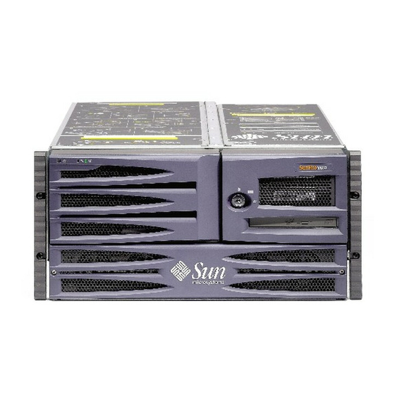
Page 43: Locating Front Panel Features
FIGURE 2-1 For information about front panel controls and indicators, see “LED Status Indicators” on page 16. Also see the Sun Fire V480 Server Parts Installation and Removal Guide for more detailed information and illustrations. Security Lock and Top Panel Lock In addition to the security lock on the system’s front panel, a top panel lock on the... -
Page 44: Led Status Indicators
RJ-45 Ethernet ports. , “Sun Fire V480 Server Front Panel Features” on page 15 and FIGURE 2-1 , “Sun Fire V480 Server Back Panel Features” on page 20 for locations of FIGURE 2-3 the front panel and back panel LEDs. -
Page 45: Table 2-1 System Leds
Listed from left to right, the system LEDs operate as described in the following table. System LEDs TABLE 2-1 Name Description Locator This white LED is lit by Sun Management Center or Sun Remote System Control software, or by Solaris command, to locate a system. -
Page 46: Power Button
In the following illustration, the system control switch is in the Locked position. System control switch Four-Position System Control Switch in Locked Position FIGURE 2-2 Sun Fire V480 Server Administration Guide • February 2002... -
Page 47: Table 2-4 System Control Switch Settings
The following table describes the function of each system control switch setting. System Control Switch Settings TABLE 2-4 Position Icon Description Normal This setting enables the system Power button to power the system on or off. If the operating system is running, pressing and releasing the Power button initiates a graceful software system shutdown. -
Page 48: Locating Back Panel Features
This amber LED lights to indicate that data is either being Activity transmitted or received by the particular port. Ethernet Link This green LED lights when a link is established at the particular port with its link partner. Sun Fire V480 Server Administration Guide • February 2002... -
Page 49: Figure 2-4 Back Panel External Ports
lists and describes the power supply LEDs on the system’s back panel. TABLE 2-6 Power Supply LEDs TABLE 2-6 Name Description Power supply This blue LED lights when it is safe to remove the power OK-to-Remove supply from the system. Power supply This amber LED lights whenever the power supply’s Fault... -
Page 50: About Reliability, Availability, And Serviceability Features
Together, reliability, availability, and serviceability features provide for near continuous system operation. To deliver high levels of reliability, availability and serviceability, the Sun Fire V480 system offers the following features: Hot-pluggable disk drives... -
Page 51: 1+1 Power Supply Redundancy
AC power source fail. For more information about power supplies, redundancy, and configuration rules, see “About the Power Supplies” on page 43. Environmental Monitoring and Control The Sun Fire V480 system features an environmental monitoring subsystem designed to protect against: Extreme temperatures... -
Page 52: Automatic System Recovery
Note – ASR functionality is not enabled until you activate it. Control over the system’s ASR functionality is provided by a number of OpenBoot PROM commands and configuration variables. For additional details, see “About Automatic System Recovery” on page 63. Sun Fire V480 Server Administration Guide • February 2002... -
Page 53: Mpxio
The RSC software works with the RSC card on the Sun Fire V480 system PCI riser board. The RSC card provides modem and private Ethernet connections to a remote console, and a serial connection to a local alphanumeric terminal. -
Page 54: Hardware Watchdog Mechanism And Xir
Guide provided with the RSC software. Hardware Watchdog Mechanism and XIR To detect and respond to system hang conditions, the Sun Fire V480 system features a hardware watchdog mechanism—a hardware timer that is continually reset as long as the operating system is running. In the event of a system hang, the operating system is no longer able to reset the timer. -
Page 55: Support For Raid Storage Configurations
Support for RAID Storage Configurations By attaching one or more external storage devices to the Sun Fire V480 server, you can use a software RAID application such as Solstice DiskSuite™ or VERITAS Volume Manager to configure system disk storage in a variety of different RAID levels. - Page 56 Sun Fire V480 Server Administration Guide • February 2002...
-
Page 57: Hardware Configuration
C H A P T E R Hardware Configuration This chapter provides hardware configuration information for the Sun Fire V480 server. The following topics are covered in this chapter: “About Hot-Pluggable and Hot-Swappable Components” on page 30 “About the CPU/Memory Boards” on page 31 “About the Memory Modules”... -
Page 58: About Hot-Pluggable And Hot-Swappable Components
About Hot-Pluggable and Hot-Swappable Components In a Sun Fire V480 system, the FC-AL disk drives are hot-pluggable components and the power supplies are hot-swappable. (No other component of the system is either hot-pluggable or hot-swappable.) Hot-pluggable components are those that you can install or remove while the system is running, without affecting the rest of the system’s capabilities. -
Page 59: Disk Drives
Fire V480 disk drive hot-plug operations, you use the Solaris luxadm utility. The luxadm utility is a command-line tool for managing intelligent storage arrays such as Sun StorEdge A5x00 series disk arrays or Sun Fire V480 internal storage arrays. For more information about luxadm, see the luxadm man page. For complete disk hot-plug procedures, see the Sun Fire V480 Server Parts Installation and Removal Guide. -
Page 60: About The Memory Modules
DIMM slots FIGURE 3-1 and DIMM groups on a Sun Fire V480 CPU/Memory board. Every fourth slot belongs to the same DIMM group. The four groups are designated A0, A1, B0, and Sun Fire V480 Server Administration Guide • February 2002... - Page 61 Memory Module Groups A0, A1, B0, B1 FIGURE 3-1 You must physically remove a CPU/Memory board from the system before you can install or remove DIMMs. The DIMMs must be added four-at-a-time within the same DIMM group, and each group used must have four identical DIMMs installed—that is, all four DIMMs in the group must be from the same manufacturing vendor and must have the same capacity (for example, four 256-Mbyte DIMMs, four 512-Mbyte DIMMs, or four 1-Gbyte DIMMs).
-
Page 62: Memory Interleaving
One CPU controls DIMM groups A0 and A1, while the other CPU controls DIMM groups B0 and B1. The Sun Fire V480 system uses a shared memory architecture. During normal system operations, the total system memory is shared by all CPUs in the system. However, in the event of a CPU failure, the two DIMM groups associated with the failed CPU become unavailable to the other CPUs in the system. -
Page 63: Configuration Rules
Note – All internal options (except disk drives and power supplies) must be installed only by qualified service personnel. For information about installing or removing DIMMs, see the Sun Fire V480 Server Parts Installation and Removal Guide, which is included on the Sun Fire V480 Documentation CD. -
Page 64: Figure
Note – PCI cards in a Sun Fire V480 system are not hot-pluggable. PCI Bus Characteristics, Associated Bridge Chips, Centerplane Devices, TABLE 3-2 and PCI Slots Clock Rate (MHz)/ Bandwidth (bits)/ PCI Bridge PCI Bus Voltage (V) Integrated Devices PCI Slots... -
Page 65: Configuration Rules
Note – All internal options (except disk drives and power supplies) must be installed only by qualified service personnel. For information about installing or removing PCI cards, see the Sun Fire V480 Server Parts Installation and Removal Guide, which is included on the Sun Fire V480 Documentation CD. -
Page 66: About The Sun Remote System Control Card
Card The Sun Remote System Control (RSC) card enables access, monitoring, and control of the Sun Fire V480 server from a remote location. It is a fully independent processor card with its own resident firmware, power-on self-test (POST) diagnostics, and real-time operating system. -
Page 67: Figure 3-4 Rsc Card Ports
The RSC card runs independently of the host server, and operates off of 5-volt standby power from the system’s power supplies. It also includes a backup battery that enables the card to continue operating for up to 30 minutes in the event of a power failure. -
Page 68: Configuration Rules
Guide, which is included on the Sun Fire V480 Documentation CD. About Hardware Jumpers Three jumpers each are located on the Sun Fire V480 system’s PCI riser board and RSC card. Note that jumpers are set at the factory to ensure best system performance. -
Page 69: Pci Riser Board Jumpers
PCI Riser Board Jumpers On the PCI riser board are three jumpers, two of which affect transactions with the system boot PROM and one of which is reserved for future use. illustrates FIGURE 3-6 the locations of these three jumpers. J1103 J1104 J1102... -
Page 70: Rsc Card Jumpers
PROM. RSC Card Jumpers The locations of jumpers on the RSC card are shown in FIGURE 3-7 J0502 J0501 J0403 Hardware Jumpers on Card FIGURE 3-7 Sun Fire V480 Server Administration Guide • February 2002... -
Page 71: About The Power Supplies
The functions of the RSC card jumpers are shown in TABLE 3-4 Card Jumper Functions TABLE 3-4 Jumper Shunt on Pins 1 + 2 Selects Shunt on Pins 2 + 3 Selects Default Setting Not used Disable mirror 2 + 3 J0502 3 2 1 Normal booting... -
Page 72: Figure 3-8 Power Supply Locations
The Sun Fire V480 system’s power supplies are modular units, designed for fast, easy installation or removal, even while the system is fully operational. Power supplies are installed in bays at the front of the system, as shown in the following figure. -
Page 73: Configuration Rule
PCI access panel to gain access to it. Power supplies are cooled separately, each with its own internal fans. Caution – Fans on a Sun Fire V480 system are not hot-pluggable. Attempting to replace a fan tray while the system is running poses an extreme risk of bodily injury. -
Page 74: Configuration Rule
Note – All internal options (except disk drives and power supplies) must be installed only by qualified service personnel. For information about installing or removing fan tray assemblies, see the Sun Fire V480 Server Parts Installation and Removal Guide, which is included on the Sun Fire V480 Documentation CD. -
Page 75: About Fc-Al Technology
About FC-AL Technology Fibre Channel (FC) is a high-performance serial interconnect standard designed for bidirectional, point-to-point communication among servers, storage systems, workstations, switches, and hubs. Fibre Channel-Arbitrated Loop (FC-AL) is an important enhancement to the FC standard, developed specifically to meet the needs of storage system interconnects. Employing a simple loop topology, FC-AL can support both simple configurations and complex arrangements of hubs, switches, servers, and storage systems. -
Page 76: About The Fc-Al Backplane
1. The 127 supported devices include the FC-AL controller required to support each arbitrated loop. About the FC-AL Backplane All Sun Fire V480 servers include a single FC-AL backplane with connections for two internal hard disks, both of which are hot-pluggable. -
Page 77: Configuration Rules
The FC-AL disks are hot-pluggable. For information about installing or removing an FC-AL disk or disk backplane, see the Sun Fire V480 Server Parts Installation and Removal Guide, which is included on the Sun Fire V480 Documentation CD. About the HSSDC FC-AL Port The Sun Fire V480 system back panel includes an FC-AL port with a high-speed serial data connector (HSSDC). -
Page 78: About The Fc-Al Host Adapters
About the FC-AL Host Adapters The Sun Fire V480 server uses an intelligent Fibre Channel processor as its on-board FC-AL controller. Integrated into the system centerplane, the processor resides on PCI Bus C and supports a 64-bit, 66-MHz PCI interface. The on-board FC-AL controller controls FC-AL operations on Loop A. -
Page 79: Configuration Rule
For your convenience, a serial port adapter (part number 530-2889-03) is included in your Sun Fire V480 server ship kit. This adapter enables you to use a standard RJ-45 serial cable to connect directly from the serial connector on the back panel to a Sun workstation, or to any other terminal that is equipped with a DB-25 serial connector. -
Page 80: About The Usb Ports
However, you can only perform USB hot-plug operations while the operating system is running. USB hot-plug operations are not supported when the system ok prompt is displayed. Sun Fire V480 Server Administration Guide • February 2002... -
Page 81: Network Interfaces And System Firmware
C H A P T E R Network Interfaces and System Firmware This chapter describes the networking options of the system and provides background information about the system’s firmware. Information covered in this chapter includes: “About the Network Interfaces” on page 54 “About Redundant Network Interfaces”... -
Page 82: About The Network Interfaces
About the Network Interfaces The Sun Fire V480 server provides two on-board Ethernet interfaces, which reside on the system centerplane and conform to the IEEE 802.3z Ethernet standard. For an illustration of the Ethernet ports, see , “Back Panel External Ports” on FIGURE 2-4 page 21. -
Page 83: About Redundant Network Interfaces
A synopsis of run levels follows; for a full description, see the Solaris system administration documentation. Most of the time, you operate a Sun Fire V480 system at run level 2, or run level 3, which are multiuser states with access to full system and network resources. -
Page 84: What You Should Know About Accessing The Ok Prompt
A serious hardware problem develops while the system is running, and the operating environment software transitions smoothly to run level 0. You deliberately place the Sun Fire V480 system under firmware control in order to execute firmware-based commands or run diagnostic tests. -
Page 85: Ways Of Reaching The Ok Prompt
When it is impossible or impractical to halt the system gracefully, you can get to the ok prompt by typing the L1-A (or Stop-A) key sequence from a Sun keyboard, or, if you have an alphanumeric terminal attached to the Sun Fire V480 system, by pressing the Break key. -
Page 86: Manual System Reset
About OpenBoot Environmental Monitoring Environmental monitoring and control capabilities for Sun Fire V480 systems reside at both the operating system level and the OpenBoot firmware level. This ensures that monitoring capabilities are operational even if the system has halted or is unable to boot. -
Page 87: Enabling Or Disabling The Openboot Environmental Monitor
Enabling or Disabling the OpenBoot Environmental Monitor The OpenBoot environmental monitor is enabled by default whenever the system is operating at the ok prompt. However, you can enable or disable it yourself using the OpenBoot commands env-on and env-off. For more information, see: “How to Enable OpenBoot Environmental Monitoring”... -
Page 88: Openboot Environmental Status Information
Specifically, the Stop-N, Stop-D, and Stop-F commands that were available on systems with non-USB keyboards are not supported on systems that use USB keyboards, such as the Sun Fire V480 system. The following sections describe the OpenBoot emergency procedures for systems with non-USB keyboards and for newer systems with USB keyboards. -
Page 89: Openboot Emergency Procedures For Systems With Non-Usb Keyboards
With USB Keyboards The following paragraphs describe how to perform the functions of the Stop commands on systems that use USB keyboards, such as the Sun Fire V480 system. These same functions are available through Sun Remote System Control (RSC). -
Page 90: Stop-F Functionality
POST” on page 84 for more information about IDPROM) to the default values. (Note that “NVRAM” in the output is synonymous with IDPROM.) Sun Fire V480 (4 X UltraSPARC-III cu 900 MHz), Keyboard Present OpenBoot x.x, 256 MB memory installed, Serial #xxxxxxxx. -
Page 91: Stop-D Functionality
Stop-D Functionality The Stop-D (Diags) key sequence is not supported on systems with USB keyboards. However, the Stop-D functionality can be closely emulated by turning the system control switch to the Diagnostics position. For more information, see “System Control Switch” on page 18. About Automatic System Recovery The system provides for automatic system recovery (ASR) from the following types of hardware component failures:... -
Page 92: Auto-Boot Options
This behavior is obviously not acceptable for a degraded boot scenario. Therefore, the Sun Fire V480 OpenBoot firmware provides a second setting, auto-boot-on-error?. This setting controls whether the system will attempt a degraded boot when a subsystem failure is detected. -
Page 93: Reset Scenarios
If only non-fatal errors are detected by POST or OpenBoot Diagnostics, the system attempts to boot if auto-boot? is true and auto-boot-on-error? is true. Non-fatal errors include the following: FC-AL subsystem failure – In this case, a working alternate path to the boot disk is required. -
Page 94: Asr User Commands
For more information, see: “How to Unconfigure a Device Manually” on page 168 “How to Reconfigure a Device Manually” on page 170 “How to Obtain ASR Status Information” on page 164 Sun Fire V480 Server Administration Guide • February 2002... -
Page 95: System Administration Software
C H A P T E R System Administration Software This chapter provides an introduction to system administration software tools supported on the Sun Fire V480 system. The following information is covered in this chapter: “About System Administration Software” beginning on page 68 “About Multipathing Software”... -
Page 96: About System Administration Software
Sun servers so that they work together as a single, highly available and scalable system. Sun Cluster software delivers high availability—through automatic fault detection and recovery—and scalability, ensuring that mission-critical applications and services are always available when needed. Sun Fire V480 Server Administration Guide • February 2002... -
Page 97: About Multipathing Software
FC-AL host bus adapters connected to the same dual-ported storage array. For Sun Fire V480 systems, three different types of multipathing software are available: Solaris IP Network Multipathing software provides multipathing and load balancing capabilities for IP network interfaces. -
Page 98: About Volume Management Software
About Volume Management Software Sun Microsystems offers two different volume management applications for use on Sun Fire V480 systems: VERITAS Volume Manager software Solstice DiskSuite software Volume management software lets you create disk volumes. Volumes are logical disk devices comprising one or more physical disks or partitions from several different disks. -
Page 99: Multiplexed I/O (Mpxio)
Multiplexed I/O (MPxIO) A newer alternative to DMP that is also supported by the Sun Fire V480 server is multiplexed I/O (MPxIO). Beginning with Solaris 8, MPxIO is fully integrated within the Solaris operating environment’s core I/O framework. MPxIO enables you... -
Page 100: Disk Concatenation
RAID 1 offers the highest level of data protection, but storage costs are high, and write performance is reduced since all data must be stored twice. Sun Fire V480 Server Administration Guide • February 2002... -
Page 101: Raid 0: Disk Striping
RAID 0: Disk Striping Disk striping (RAID 0) is a technique for increasing system throughput by using several disk drives in parallel. Whereas in non-striped disks the operating system writes a single block to a single disk, in a striped arrangement, each block is divided and portions of the data are written to different disks simultaneously. -
Page 102: For More Information
For More Information See the documentation supplied with the Sun Cluster software. Sun Fire V480 Server Administration Guide • February 2002... -
Page 103: About Communicating With The System
You use the system console to view messages and issue commands. The system console is unique—there can be only one per system. During initial installation of the Sun Fire V480 system and the Solaris operating environment software, you must use the built-in serial port (ttya) to access the system console. -
Page 104: Using The System Console
Default System Console Configuration On Sun Fire V480 servers, the system console comes preconfigured to allow input and output only by means of an alphanumeric terminal or tip line attached to the system’s built-in serial port, ttya. This provides for secure access at the installation site. - Page 105 Using a Local Graphics Terminal as the System Console The Sun Fire V480 server is shipped without a mouse, keyboard, monitor, or frame buffer for the display of graphics. To install a local graphics terminal on the server, you must install a graphics frame buffer card into a PCI slot, and attach a monitor, mouse, and keyboard to the appropriate back panel ports.
- Page 106 Sun Fire V480 Server Administration Guide • February 2002...
-
Page 107: Diagnostic Tools
C H A P T E R Diagnostic Tools The Sun Fire V480 server and its accompanying software contain many tools and features that help you: Isolate problems when there is a failure of a field-replaceable component Monitor the status of a functioning system... -
Page 108: About The Diagnostic Tools
About the Diagnostic Tools Sun provides a wide spectrum of diagnostic tools for use with the Sun Fire V480 server. These tools range from the formal—like Sun’s comprehensive Validation Test Suite (SunVTS), to the informal—like log files that may contain clues helpful in narrowing down the possible sources of a problem. - Page 109 Summary of Diagnostic Tools (Continued) TABLE 6-1 Remote Diagnostic Tool Type What It Does Accessibility and Availability Capability SunVTS Software Exercises and stresses the system, Requires operating system. View and running tests in parallel Optional package may control over need to be installed network Hardware Monitors environmental...
- Page 110 Consider the data bus built into every Sun Fire V480 server. This bus features a five- way switch called a CDX that interconnects all CPUs and high-speed I/O interfaces (see ). This data switch enables multiple simultaneous transfers over its FIGURE 6-1 private data paths.
- Page 111 Consider also that some diagnostics must function even when the system fails to start. Any diagnostic capable of isolating problems when the system fails to start up must be independent of the operating system. But any diagnostic that is independent of the operating system will also be unable to make use of the operating system’s considerable resources for getting at the more complex causes of failures.
-
Page 112: About Diagnostics And The Boot Process
Stage One: OpenBoot Firmware and POST Every Sun Fire V480 server includes a chip holding about 2 Mbytes of firmware- based code. This chip is called the Boot PROM. After you turn on system power, the first thing the system does is execute code that resides in the Boot PROM. -
Page 113: What Are Post Diagnostics For
When system power is turned on, the OpenBoot firmware begins running directly out of the Boot PROM, since at this stage system memory has not been verified to work properly. Soon after power is turned on, the Boot Bus controller and other system hardware determine that at least one CPU module is powered on, and is submitting a bus access request, which indicates that the CPU in question is at least partly functional. -
Page 114: What Post Diagnostics Do
1>ERROR: TEST = Data Bitwalk on Slave 3 1>H/W under test = CPU3 Memory 1>MSG = ERROR: miscompare on mem test! Address: 00000030.001b0038 Expected: 00000000.00100000 Observed: 00000000.00000000 Sun Fire V480 Server Administration Guide • February 2002... -
Page 115: What Post Error Messages Tell You
What POST Error Messages Tell You When a specific power-on self-test discloses an error, it reports different kinds of information about the error: The specific test that failed The specific circuit or subcomponent that is most likely at fault The field-replaceable units (FRUs) most likely to require replacement, in order of likelihood Here is an excerpt of POST output showing another error message. -
Page 116: Controlling Post Diagnostics
FRU is responsible. If this seems counter-intuitive, consider the block diagram of one data path within a Sun Fire V480 server, shown in FIGURE 6-3 5-way... - Page 117 lists the most important and useful of these variables. You can find TABLE 6-2 instructions for changing OpenBoot configuration variables in “How to View and Set OpenBoot Configuration Variables” on page 184. OpenBoot Configuration Variables TABLE 6-2 OpenBoot Configuration Variable Description and Keywords Determines whether the operating system automatically starts up.
-
Page 118: Stage Two: Openboot Diagnostics Tests
OpenBoot firmware code compiles a hierarchical “census” of all devices in the system. This census is called a device tree. Though different for every system configuration, the device tree generally includes both built-in system components and optional PCI bus devices. Sun Fire V480 Server Administration Guide • February 2002... -
Page 119: What Are Openboot Diagnostics Tests For
OpenBoot Diagnostics tests focus on system I/O and peripheral devices. Any device in the device tree, regardless of manufacturer, that includes an IEEE 1275-compatible self-test is included in the suite of OpenBoot Diagnostics tests. On a Sun Fire V480 server, OpenBoot Diagnostics test the following system components: I/O interfaces;... -
Page 120: Table 6-3 Keywords For The Test-Args Openboot Configuration Variable
It is easiest to run OpenBoot Diagnostics tests interactively from a menu. You access the menu by typing obdiag at the ok prompt. See “How to Isolate Faults Using Interactive OpenBoot Diagnostics Tests” on page 180 for full instructions. Sun Fire V480 Server Administration Guide • February 2002... - Page 121 The obdiag> prompt and the OpenBoot Diagnostics interactive menu ( FIGURE 6-4 appear. For a brief explanation of each OpenBoot Diagnostics test, see TABLE 6-10 “Reference for OpenBoot Diagnostics Test Descriptions” on page 116. o b d i a g 1 SUNW,qlc@2 2 bbc@1,0 3 ebus@1...
- Page 122 /pci@x,y/SUNW,qlc@2 Note – Knowing how to construct an appropriate hardware device path requires precise knowledge of the hardware architecture of the Sun Fire V480 system. To customize an individual test, you can use test-args as follows: ok test /usb@1,3:test-args={verbose,debug} This affects only the current test without changing the value of the test-args OpenBoot configuration variable.
-
Page 123: What Openboot Diagnostics Error Messages Tell You
CODE EXAMPLE 6-2 C Bus Device Tests OpenBoot Diagnostics tests examine and report on i2c@1,2e i2c@1,30 environmental monitoring and control devices connected to the Sun Fire V480 server’s Inter-IC (I C) bus. Error and status messages from the OpenBoot Diagnostics... -
Page 124: Other Openboot Commands
Beyond the formal firmware-based diagnostic tools, there are a few commands you can invoke from the ok prompt. These OpenBoot commands display information that can help you assess the condition of a Sun Fire V480 server. These include the: .env command... - Page 125 The probe-scsi command communicates with all SCSI and FC-AL devices connected to on-board SCSI and FC-AL controllers. The probe-scsi-all command additionally accesses devices connected to any host adapters installed in PCI slots. For any SCSI or FC-AL device that is connected and active, the probe-scsi and probe-scsi-all commands display its loop ID, host adapter, logical unit number, unique World Wide Name (WWN), and a device description that includes type and manufacturer.
- Page 126 (edited for CODE EXAMPLE 6-6 brevity). /pci@9,600000 /pci@9,700000 /pci@8,600000 /pci@8,700000 /memory-controller@3,400000 /SUNW,UltraSPARC-III@3,0 /memory-controller@1,400000 /SUNW,UltraSPARC-III@1,0 /virtual-memory /memory@m0,20 /pci@9,600000/SUNW,qlc@2 /pci@9,600000/network@1 /pci@9,600000/SUNW,qlc@2/fp@0,0 /pci@9,600000/SUNW,qlc@2/fp@0,0/disk show-devs Command Output CODE EXAMPLE 6-6 Sun Fire V480 Server Administration Guide • February 2002...
-
Page 127: Stage Three: The Operating Environment
In addition to the formal tools that run on top of Solaris operating environment software, there are other resources that you can use when assessing or monitoring the condition of a Sun Fire V480 server. These include: Error and system message log files... -
Page 128: Prtconf Command
(see “show-devs Command” on page 98). This output lists only those devices compiled by the system firmware. prtdiag Command The prtdiag command displays a table of diagnostic information that summarizes the status of system components. Sun Fire V480 Server Administration Guide • February 2002... - Page 129 The display format used by the prtdiag command can vary depending on what version of the Solaris operating environment is running on your system. Following is an excerpt of some of the output produced by prtdiag on a healthy Sun Fire V480 system running Solaris 8, Update 7. System Configuration: Sun Microsystems...
-
Page 130: Prtfru Command
Fault Indication Output CODE EXAMPLE 6-11 prtfru Command The Sun Fire V480 system maintains a hierarchical list of all FRUs in the system, as well as specific information about various FRUs. Sun Fire V480 Server Administration Guide • February 2002... - Page 131 The prtfru command can display this hierarchical list, as well as data contained in the serial electrically-erasable programmable read-only memory (SEEPROM) devices located on many FRUs. shows an excerpt of a hierarchical list of CODE EXAMPLE 6-12 FRUs generated by the prtfru command with the -l option. /frutree /frutree/chassis (fru) /frutree/chassis/io-board (container)
-
Page 132: Psrinfo Command
Information about the following Sun Fire V480 FRUs is displayed by the prtfru command: Centerplane CPU/Memory boards DIMMs FC-AL disk backplane FC-AL disk drive PCI riser Power distribution board Power supplies RSC card psrinfo Command The psrinfo command displays the date and time each CPU came online. With the verbose (-v) option, the command displays additional information about the CPUs, including their clock speed. - Page 133 showrev Command The showrev command displays revision information for the current hardware and software. shows sample output of the showrev command. CODE EXAMPLE 6-15 Hostname: abc-123 Hostid: cc0ac37f Release: 5.8 Kernel architecture: sun4u Application architecture: sparc Hardware provider: Sun_Microsystems Domain: Sun.COM Kernel version: SunOS 5.8 cstone_14:08/01/01 2001 showrev Command Output CODE EXAMPLE 6-15...
-
Page 134: Tools And The Boot Process: A Summary
FRUs TABLE 6-5 in a Sun Fire V480 system. The available diagnostic tools are shown in column headings across the top. A check mark ( ) in this table indicates that a fault in a particular FRU can be isolated by a particular diagnostic. -
Page 135: Table 6-6 Frus Not Directly Isolated By Diagnostic Tools
FRU Coverage of Fault Isolating Tools (Continued) TABLE 6-5 LEDs POST OpenBoot Diags RSC Card PCI Riser FC-AL Disk Backplane Power Supplies Fan Tray 0 (CPU) Fan Tray 1 (I/O) In addition to the FRUs listed in , there are several minor replaceable TABLE 6-5 system components—mostly cables—that cannot directly be isolated by any system diagnostic. -
Page 136: About Monitoring The System
The RSC card also includes a backup battery that supplies approximately 30 minutes of power to the RSC card in case of a complete system power failure. Sun Fire V480 Server Administration Guide • February 2002... -
Page 137: Monitoring The System Using Sun Management Center
RSC. The latter task is described in “How to Redirect the System Console to RSC” on page 165. For instructions on using RSC to monitor a Sun Fire V480 system, see “How to Monitor the System Using RSC” on page 195. -
Page 138: How Sun Management Center Works
Sun Management Center lets you monitor the following on the Sun Fire V480 server. What Sun Management Center Monitors TABLE 6-8 Item Monitored What Sun Management Center Reveals Disk drives Whether each slot has a drive present, and whether it reports... -
Page 139: Other Sun Management Center Features
Other Sun Management Center Features Sun Management Center software provides you with additional tools in the form of an informal tracking mechanism and an optional add-on diagnostics suite. In a heterogeneous computing environment, the product can interoperate with management utilities made by other companies. Informal Tracking Sun Management Center agent software must be loaded on any system you want to monitor. -
Page 140: Obtaining The Latest Information
Sun provides two tools for exercising Sun Fire V480 systems: Sun Validation Test Suite (SunVTS™) Hardware Diagnostic Suite shows the FRUs that each system exercising tool is capable of isolating. -
Page 141: Exercising The System Using Sunvts Software
The Sun Fire V480 server to be tested must be up and running if you want to use SunVTS software, since it relies on the Solaris operating environment. Since SunVTS software packages are optional, they may not be installed on your system. -
Page 142: Sunvts Software And Security
For instructions on running SunVTS software to exercise the Sun Fire V480 server, see “How to Exercise the System Using SunVTS Software” on page 206. For more information about the product, see: SunVTS User’s Guide (816-1575-10) – Describes SunVTS features as well as how to start and control the various user interfaces. -
Page 143: When To Run Hardware Diagnostic Suite
Sequential testing means the Hardware Diagnostic Suite has a low impact on the system. Unlike SunVTS, which stresses a system by consuming its resources with many parallel tests (see “Exercising the System Using SunVTS Software” on page 113), the Hardware Diagnostic Suite lets the server run other applications while testing proceeds. -
Page 144: Reference For Openboot Diagnostics Test Descriptions
Same as above, for the other on-board Ethernet controller Centerplane network@2 Tests the registers of the power management controller PCI riser board pmc@1,300700 Tests RSC hardware, including the RSC serial and Ethernet RSC card rsc-control@1,3062f8 ports Sun Fire V480 Server Administration Guide • February 2002... -
Page 145: Table 6-11 Openboot Diagnostics Test Menu Commands
OpenBoot Diagnostics Menu Tests (Continued) TABLE 6-10 Test Name What It Does FRU(s) Tested Tests the registers of the real-time clock and then tests the PCI riser board rtc@1,300070 interrupt rates Tests all possible baud rates supported by the ttya serial Centerplane, serial@1,400000 line. -
Page 146: Reference For Decoding I2C Diagnostic Test Messages
Reference for Decoding I C Diagnostic Test Messages describes each I C device in a Sun Fire V480 system, and helps you TABLE 6-12 associate each I C address with the proper FRU. For more information about I tests, see “I2C Bus Device Tests” on page 95. - Page 147 Sun Fire V480 I C Bus Devices (Continued) TABLE 6-12 Address Associated FRU What the Device Does fru@2,a0 CPU 2, DIMM 0 fru@2,a2 CPU 2, DIMM 1 fru@2,a4 CPU 2, DIMM 2 fru@2,a6 CPU 2, DIMM 3 Provides configuration information for CPU 2 DIMMs...
- Page 148 FC-AL disk backplane Provides disk backplane configuration information fru@5,ae Power distribution board Provides configuration information for the power distribution board and the enclosure fru@5,d0 RSC card Monitors RSC’s real-time clock Sun Fire V480 Server Administration Guide • February 2002...
-
Page 149: Reference For Terms In Diagnostic Output
Reference for Terms in Diagnostic Output The status and error messages displayed by POST diagnostics and OpenBoot Diagnostics tests occasionally include acronyms or abbreviations for hardware sub- components. is included to assist you in decoding this terminology and TABLE 6-13 associating the terms with specific FRUs, where appropriate. - Page 150 Centerplane UART Universal Asynchronous Receiver Transmitter – Centerplane, PCI riser Serial port hardware board, RSC card Update-ended Interrupt Enable – A function PCI riser board provided by the SuperIO integrated circuit Sun Fire V480 Server Administration Guide • February 2002...
-
Page 151: Part Three - Instructions
Part Three – Instructions The six chapters within this part of the Sun Fire V480 Server Administration Guide use illustrated instructions on how to set up various components within your system, configure your system, and diagnose problems. Instructions within this guide are primarily to be used by experienced system administrators who are familiar with the Solaris operating environment and its commands. -
Page 153: Configuring Devices
C H A P T E R Configuring Devices This chapter includes instructions on how to install your Ethernet cables and set up terminals. Tasks covered in this chapter include: “How to Avoid Electrostatic Discharge” on page 126 “How to Power On the System” on page 128 “How to Power Off the System”... -
Page 154: How To Avoid Electrostatic Discharge
Before You Begin Complete this task: “How to Power Off the System” on page 130 If you are servicing any internal components, see the Sun Fire V480 Server Parts Installation and Removal Guide for detailed instructions. You must have the following items:... -
Page 155: What Next
2. Use an antistatic mat or similar surface. When performing any installation or service procedure, place static-sensitive parts, such as boards, cards, and disk drives, on an antistatic surface. The following items can be used as an antistatic surface: The bag used to wrap a Sun replacement part The shipping container used to package a Sun replacement part Sun electrostatic discharge (ESD) mat, Sun part number 250-1088 (available through your Sun sales representatives) -
Page 156: How To Power On The System
Read the documentation supplied with the device for specific instructions. 2. Turn on power to the ASCII terminal or local graphics terminal, if present. 3. Open the media door. Use the system key to unlock the media door. Media door Sun Fire V480 Server Administration Guide • February 2002... - Page 157 4. Insert the system key into the system control switch and turn the system control switch to the Normal or Diagnostics position. See “System Control Switch” on page 18 for information about each system control switch setting. Diagnostics position Normal position Power button 5.
-
Page 158: How To Power Off The System
Applications running on the Solaris operating environment can be adversely affected by a poorly executed system shutdown. Make sure you have gracefully shut down any applications before powering off the system. Sun Fire V480 Server Administration Guide • February 2002... - Page 159 What to Do 1. Notify users that the system will be powered down. 2. Back up the system files and data, if necessary. 3. Ensure that the system control switch is in the Normal or Diagnostics position. 4. Press and release the Power button on the system front panel. The system begins a graceful software system shutdown.
-
Page 160: How To Get To The Ok Prompt
For details about when to use each method, see: “About the ok Prompt” on page 55 Note – Dropping the Sun Fire V480 system to the ok prompt suspends all application and operating environment software. After you issue firmware commands and run firmware-based tests from the ok prompt, the system may not be able simply to resume where it left off. -
Page 161: How To Attach A Twisted-Pair Ethernet Cable
Cable Before You Begin Complete the prerequisite installation steps in Chapter 1. Install the server in the rack, following instructions in the Sun Fire V480 Server Setup and Rackmounting Guide. What to Do 1. Locate the RJ-45 twisted-pair Ethernet (TPE) connector for the appropriate Ethernet interface—the top connector or the bottom connector. -
Page 162: How To Access The System Console Via Tip Connection
The following procedure assumes you are connecting to the serial port (ttya) of the Sun Fire V480 system using a tip connection from serial port B (ttyb) of another Sun server, and that the other Sun server has its own local graphics terminal. - Page 163 For details, see “Controlling POST Diagnostics” on page 88. 3. Connect the RJ-45 serial cable and adapter. The cable and adapter connect the Sun server’s ttyb serial port to the Sun Fire V480 system’s built-in ttya serial port. Pinouts, part numbers, and other details about the serial cable and adapter are provided in the Sun Fire V480 Server Parts Installation and Removal Guide.
-
Page 164: How To Modify The /Etc/Remote File
The Sun server responds by displaying: connected The shell tool is now a tip window directed to the Sun Fire V480 system via the Sun server’s ttyb port. This connection is established and maintained even if the Sun Fire V480 system is completely powered off or just starting up. - Page 165 What to Do 1. Determine the release level of system software installed on the Sun server. To do this, type: # uname -r The system responds with a release number. 2. Do one of the following, depending on the number displayed. If the number displayed by the uname -r command is 5.0 or higher: The server software shipped with an appropriate entry for hardwire in the /etc/remote file.
-
Page 166: How To Verify Serial Port Settings
This procedure lets you verify the baud rate and other serial port settings used by the Sun Fire V480 server to communicate with attached serial port devices. Before You Begin You must be logged in to the Sun Fire V480 server, and the server must be running Solaris operating environment software. What to Do 1. -
Page 167: How To Set Up An Alphanumeric Terminal As The System Console
Use an RJ-45 null modem serial cable or an RJ-45 serial cable and null modem adapter. Plug this into the terminal’s serial port connector. 2. Attach the opposite end of the serial cable to the Sun Fire V480 system. Plug the cable into the system’s built-in serial port (ttya) connector. - Page 168 OpenBoot variable auto-boot? is set to true (its default value). What Next You can issue system commands and view system messages on the ASCII terminal. Continue with your installation or diagnostic procedure as needed. Sun Fire V480 Server Administration Guide • February 2002...
-
Page 169: How To Configure A Local Graphics Terminal As The System Console
1. Install the graphics card into an appropriate PCI slot. Installation must be performed by a qualified service provider. For further information, see the Sun Fire V480 Server Parts Installation and Removal Guide or contact your qualified service provider. Chapter 7 Configuring Devices... - Page 170 2. Attach the monitor video cable to the graphics card’s video port. Tighten the thumbscrews to secure the connection. Sun Fire V480 Server Administration Guide • February 2002...
- Page 171 3. Connect the monitor’s power cord to an AC outlet. 4. Connect the keyboard USB cable to any USB port on the back panel. 5. Connect the mouse USB cable to any USB port on the back panel. Chapter 7 Configuring Devices...
-
Page 172: How To Initiate A Reconfiguration Boot
C bus, including memory modules, CPU/Memory boards, and power supplies. This requirement does not apply to any component that is: Installed or removed as part of a hot-plug or hot-swap operation Sun Fire V480 Server Administration Guide • February 2002... - Page 173 To issue software commands, you need to set up a system ASCII terminal, a local graphics terminal, or a tip connection to the Sun Fire V480 system. See: “How to Set Up an Alphanumeric Terminal as the System Console” on page 139 “How to Configure a Local Graphics Terminal as the System Console”...
- Page 174 See: “How to Power Off the System” on page 130 “About Communicating With the System” on page 75 For information about system troubleshooting and diagnostics, see Chapter 6. Sun Fire V480 Server Administration Guide • February 2002...
-
Page 175: Reference For System Console Openboot Variable Settings
Reference for System Console OpenBoot Variable Settings Certain OpenBoot configuration variables control from where system console input is taken and to where its output is directed. The table below shows how to set these variables in order to use ttya, RSC, or a local graphics terminal as the system console. - Page 176 Sun Fire V480 Server Administration Guide • February 2002...
-
Page 177: Configuring Network Interfaces And The Boot Device
C H A P T E R Configuring Network Interfaces and the Boot Device This chapter provides information and instructions that are required to plan and to configure the supported network interfaces. Tasks covered in this chapter include: “How to Configure the Primary Network Interface” on page 150 “How to Configure Additional Network Interfaces”... -
Page 178: How To Configure The Primary Network Interface
(-). Do not use a dot in the host name. Do not begin the name with a number or a special character. The name must not be longer than 30 characters. Sun Fire V480 Server Administration Guide • February 2002... - Page 179 4. Determine the unique Internet Protocol (IP) address of the network interface and make a note of it. You need to furnish the address in a later step. An IP address must be assigned by the network administrator. Each network device or interface must have a unique IP address.
-
Page 180: How To Configure Additional Network Interfaces
Note – The Sun Fire V480 system conforms to the Ethernet 10/100BASE-T standard, which states that the Ethernet 10BASE-T link integrity test function should always be enabled on both the host system and the Ethernet hub. If you have problems establishing a connection between this system and your hub, verify that the Ethernet hub also has the link test function enabled. - Page 181 What to Do 1. Choose a network host name for each new interface. The host name must be unique within the network. It can consist only of alphanumeric characters and the dash (-). Do not use a dot in the host name. Do not begin the name with a number or a special character.
- Page 182 7. Manually plumb and enable each new interface using the ifconfig command. For example, for the interface ce2, type: sunrise # ifconfig ce2 plumb up For more information, see the ifconfig(1M) man page. Sun Fire V480 Server Administration Guide • February 2002...
-
Page 183: How To Select The Boot Device
This document is available on the Solaris on Sun Hardware AnswerBook, which is provided on the Computer Systems Supplement CD for your specific Solaris release. Note – The Sun Fire V480 system conforms to the Ethernet 10/100BASE-T standard, which states that the Ethernet 10BASE-T link integrity test function should always be enabled on both the host system and the Ethernet hub. - Page 184 The show-devs command lists the system devices and displays the full path name of each PCI device. Sun Fire V480 Server Administration Guide • February 2002...
- Page 185 What Next For more information about using the OpenBoot firmware, see: OpenBoot 4.x Command Reference Manual in the OpenBoot Collection AnswerBook for your specific Solaris release Chapter 8 Configuring Network Interfaces and the Boot Device...
- Page 186 Sun Fire V480 Server Administration Guide • February 2002...
-
Page 187: Configuring System Firmware
C H A P T E R Configuring System Firmware This chapter describes OpenBoot firmware commands and configuration variables available for configuring the following aspects of Sun Fire V480 system behavior: OpenBoot environmental monitoring Automatic system recovery (ASR) In addition, this chapter provides information about keyboard commands and alternative methods for performing OpenBoot emergency procedures. -
Page 188: How To Enable Openboot Environmental Monitoring
The commands env-on and env-off only affect environmental monitoring at the OpenBoot level. They have no effect on the system’s environmental monitoring and control capabilities while the operating system is running. Sun Fire V480 Server Administration Guide • February 2002... -
Page 189: How To Obtain Openboot Environmental Status Information
Using the Stop-A keyboard command to enter the OpenBoot environment immediately disables the OpenBoot environmental monitor. If you enter the OpenBoot environment through any other means—by halting the operating system, by power-cycling the system, or as a result of a system panic—the OpenBoot environmental monitor remains enabled. -
Page 190: How To Enable The Watchdog Mechanism And Its Options
At the system ok prompt, type the following. ok setenv error-reset-recovery = boot To generate automated crash dumps in case of system hangs: At the system ok prompt, type the following. ok setenv error-reset-recovery = sync Sun Fire V480 Server Administration Guide • February 2002... -
Page 191: How To Enable Asr
How to Enable ASR The automatic system recovery (ASR) feature is not activated until you enable it at the system ok prompt. What to Do 1. At the system ok prompt, type: ok setenv diag-switch? true ok setenv auto-boot? true ok setenv auto-boot-on-error? true 2. -
Page 192: How To Disable Asr
How to Obtain ASR Status Information Use the following procedure to retrieve information about the status of the automatic system recovery (ASR) feature. What to Do At the system ok prompt, type: ok .asr Sun Fire V480 Server Administration Guide • February 2002... -
Page 193: How To Redirect The System Console To Rsc
In the .asr command output, any devices marked disabled have been manually unconfigured using the asr-disable command. The .asr command also lists devices that have failed firmware diagnostics and have been automatically unconfigured by the OpenBoot ASR feature. What Next For more information, see: “About Automatic System Recovery”... -
Page 194: How To Restore The Local System Console
For more information about RSC, see: “About the Sun Remote System Control Card” on page 38 Sun Remote System Control (RSC) User’s Guide Sun Fire V480 Server Administration Guide • February 2002... -
Page 195: To Restore The Local Console To Your Ttya Port
What to Do Depending on whether you want to restore the local system console to your local ttya port or to your local graphics console, choose one of the following procedures. To Restore the Local Console to Your ttya Port 1. -
Page 196: How To Unconfigure A Device Manually
Any full physical device path as reported by the OpenBoot show-devs command Any valid device alias as reported by the OpenBoot devalias command Any device identifier from the following table Sun Fire V480 Server Administration Guide • February 2002... - Page 197 Note – The device identifiers are not case-sensitive; you can type them as uppercase or lowercase characters. Device Identifiers Devices cpu0, cpu1, ... CPU 0 – CPU 3 All CPUs cpu* cpu0-bank0, cpu0-bank1, cpu0-bank2, cpu0-bank3, ... Memory banks 0 – 3 for each CPU cpu3-bank0, cpu3-bank1, cpu3-bank2, cpu3-bank3 cpu0-bank*, cpu1-bank*, ...
-
Page 198: How To Reconfigure A Device Manually
“How to Reconfigure a Device Manually” on page 170 How to Reconfigure a Device Manually You can use the OpenBoot asr-enable command to reconfigure any device that you previously unconfigured with asr-disable. Sun Fire V480 Server Administration Guide • February 2002... - Page 199 What to Do 1. At the system ok prompt, type: ok asr-enable device-identifier where the device-identifier is one of the following: Any full physical device path as reported by the OpenBoot show-devs command Any valid device alias as reported by the OpenBoot devalias command Any device identifier from the following table Note –...
- Page 200 Sun Fire V480 Server Administration Guide • February 2002...
-
Page 201: Isolating Failed Parts
This chapter guides you in choosing the best tools and describes how to use these tools to reveal a failed part in your Sun Fire V480 server. It also explains how to use the Locator LED to isolate a failed system in a large equipment room. -
Page 202: How To Operate The Locator Led
From the RSC GUI main screen, click the representation of the Locator LED. See the illustration under Step 5 on page 198. With each click, the LED will change state from off to on, or vice versa. Sun Fire V480 Server Administration Guide • February 2002... -
Page 203: How To Put The Server In Diagnostic Mode
2. Turn the Locator LED off. Do one of the following: As root, type: # /usr/sbin/locator -f At the system console as accessed through RSC, type: rsc> setlocator off From the RSC main screen, click the representation of the Locator LED. See the illustration under Step 5 on page 198. -
Page 204: How To Isolate Faults Using Leds
For details on setting up RSC and Sun Management Center software, see: Sun Remote System Control (RSC) User’s Guide Sun Management Center Software User’s Guide Sun Fire V480 Server Administration Guide • February 2002... - Page 205 What to Do 1. Check the system LEDs. There is a group of three LEDs located near the top left corner of the front panel and duplicated on the back panel. Their status can tell you the following. Indicates Action Locator (left) A system administrator can Identify the system.
- Page 206 There are two LEDs for each Ethernet port—they are close to the right side of each Ethernet receptacle on the back panel. If the Sun Fire V480 system is connected to an Ethernet network, the status of the Ethernet LEDs can tell you the following.
-
Page 207: How To Isolate Faults Using Post Diagnostics
What to Do 1. Set up a console for viewing POST messages. Connect an alphanumeric terminal to the Sun Fire V480 server or establish a tip connection to another Sun system. See: “How to Set Up an Alphanumeric Terminal as the System Console” on page 139 “How to Access the System Console via tip Connection”... -
Page 208: How To Isolate Faults Using Interactive Openboot Diagnostics Tests
Try replacing the FRU or FRUs indicated by POST error messages, if any. For replacement instructions, see: Sun Fire V480 Server Parts Installation and Removal Guide If the POST diagnostics did not turn up any problems, but your system does not start up, try running the interactive OpenBoot Diagnostics tests. - Page 209 What to Do 1. Halt the server to reach the ok prompt. How you do this depends on the system’s condition. If possible, you should warn users and shut the system down gracefully. For information, see “About the ok Prompt” on page 55. 2.
- Page 210 What Next Try replacing the FRU or FRUs indicated by OpenBoot Diagnostics error messages, if any. For replacement instructions, see: Sun Fire V480 Server Parts Installation and Removal Guide Sun Fire V480 Server Administration Guide • February 2002...
-
Page 211: How To View Diagnostic Test Results After The Fact
How to View Diagnostic Test Results After the Fact Summaries of the results from the most recent power-on self-test (POST) and OpenBoot Diagnostics tests are saved across power cycles. Before You Begin You must set up a system console. See: “About Communicating With the System”... -
Page 212: How To View And Set Openboot Configuration Variables
Variable Name Value Default Value diag-level diag-switch? false false To set or change the value of an OpenBoot configuration variable, use the setenv command: ok setenv diag-level max diag-level = Sun Fire V480 Server Administration Guide • February 2002... -
Page 213: Reference For Choosing A Fault Isolation Tool
Reference for Choosing a Fault Isolation Tool This section helps you choose the right tool to isolate a failed part in a Sun Fire V480 system. Consider the following questions when selecting a tool. 1. Have you checked the LEDs? Certain system components have built-in LEDs that can alert you when that component requires replacement. - Page 214 Run POST system exerciser POST failure Replace part Run OBDiag OBDiag failure Disk Software or Software Check disks failure problem disk problem Choosing a Tool to Isolate Hardware Faults FIGURE 10-1 Sun Fire V480 Server Administration Guide • February 2002...
- Page 215 4. Do you intend to run the tests remotely? Both Sun Management Center and RSC software enable you to run tests from a remote computer. In addition, RSC provides a means of redirecting system console output, allowing you remotely to view and run tests—like POST diagnostics—that usually require physical proximity to the serial port on the computer’s back panel.
- Page 216 Sun Fire V480 Server Administration Guide • February 2002...
-
Page 217: Monitoring The System
This chapter describes the tasks necessary to use these tools to monitor your Sun Fire V480 server. These include: “How to Monitor the System Using Sun Management Center Software” on page 190 “How to Monitor the System Using RSC”... -
Page 218: How To Monitor The System Using Sun Management Center Software
Before You Begin This procedure assumes you intend to load Sun Management Center agent software on your Sun Fire V480 system so as to be able to monitor it, and gives you some guidance on how to accomplish this goal. - Page 219 1. On your Sun Fire V480 system, install Sun Management Center agent software. For instructions, see the Sun Management Center Supplement for Workgroup Servers. 2. On your Sun Fire V480 system, run the setup utility to configure agent software. The setup utility is part of the workgroup server supplement. For more information, see the Sun Management Center Supplement for Workgroup Servers.
- Page 220 Select “Physical View: system” from the Views pull-down menu. The physical view lets you interact with photo-realistic views of the Sun Fire V480 system as seen from the front, left, rear, and top. As you highlight individual hardware components and features, status and manufacturing information about each component appears to the right.
- Page 221 For more information about physical and logical views, see the Sun Management Center Software User’s Guide. 7. Monitor the Sun Fire V480 system using Config-Reader module data property tables. To access this information: a. Click the Browser tab.
- Page 222 In particular, you may be interested in setting alarms and administering security. These topics and many others are covered in the Sun Management Center Software User’s Guide, as well as the other documents accompanying the Sun Management Center software. Sun Fire V480 Server Administration Guide • February 2002...
-
Page 223: How To Monitor The System Using Rsc
Before You Begin The Sun Fire V480 server must be set up with RSC server software, which is installed by default from the Operating System Supplemental CD disk. Typically, you monitor the Sun Fire V480 system from a different Sun computer or a PC. - Page 224 When configuring alerts, provide the SMTP server’s IP address: SMTP Server IP address []: 123.111.111.111 g. Provide the email address of the person(s) you want to be notified: Email address []: myname@mycom.com Sun Fire V480 Server Administration Guide • February 2002...
- Page 225 Setting User Password Now ... Password: Re-enter Password: The RSC firmware on the Sun Fire V480 system is configured. Perform the following steps on the monitoring system. 3. From the monitoring Sun computer or PC, start the RSC GUI. Do one of the following.
- Page 226 5. Note the main screen’s features. The left side of the main screen provides help text and navigation controls. The right side shows a representation of the Sun Fire V480 server’s front panel and system control switch. Disk drive LEDs...
- Page 227 Proceeding will actually turn system power off (or on). Power button b. Examine status tables for the Sun Fire V480 server’s disks and fans. Click the appropriate LEDs. A table appears giving you the status of the components in question.
- Page 228 If a problem does occur, RSC brings it to your attention by displaying a failure or warning symbol over each affected graph, and more prominently, in each affected tab. Warning symbols c. Click the other Environmental Status window tabs to see additional data. Sun Fire V480 Server Administration Guide • February 2002...
- Page 229 8. Access the Sun Fire V480 server’s system console from RSC. To do this: a. Find the navigation panel at the left side of the RSC GUI. b. Click the Open Console item under Server Status and Control. A Console window appears.
- Page 230 123.111.111.111 What Next If you plan to use RSC to control the Sun Fire V480 server, you may want to configure additional RSC user accounts. You may also want to set up pager alerts. If you want to try the RSC command-line interface, you can use the telnet command to connect directly to the RSC card using the device’s name or IP address.
-
Page 231: How To Use Solaris System Information Commands
Commands This section explains how to run Solaris system information commands on a Sun Fire V480 server. To find out what these commands tell you, see “Solaris System Information Commands” on page 99, or see the appropriate man pages. Before You Begin The operating system must be up and running. -
Page 232: How To Use Openboot Information Commands
This section explains how to run OpenBoot commands that display different kinds of system information about a Sun Fire V480 server. To find out what these commands tell you, see “Other OpenBoot Commands” on page 96, or refer to the appropriate man pages. -
Page 233: Exercising The System
Sun Management Center Software User’s Guide. This chapter describes the tasks necessary to use SunVTS software to exercise your Sun Fire V480 server. These include: “How to Exercise the System Using SunVTS Software” on page 206 “How to Check Whether SunVTS Software Is Installed”... -
Page 234: How To Exercise The System Using Sunvts Software
Functional mode. For a synopsis of the modes, see: “Exercising the System Using SunVTS Software” on page 113 This procedure also assumes the Sun Fire V480 server is “headless”—that is, it is not equipped with a graphics display. In this case, you access the SunVTS GUI by logging in remotely from a machine that has a graphics display. - Page 235 On the display system, type: # /usr/openwin/bin/xhost + test-system Replace test-system with the name of the Sun Fire V480 system being tested. 3. Remotely log in to the Sun Fire V480 system as superuser. Use a command such as rlogin.
- Page 236 Tests are enabled when checked, and disabled when not checked. lists tests that are TABLE 12-1 especially useful to run on a Sun Fire V480 system. Sun Fire V480 Server Administration Guide • February 2002...
-
Page 237: Table 12-1 Useful Sunvts Tests To Run On A Sun Fire V480 System
You can customize individual tests by left-clicking on the name of the test. For instance, in the illustration under Step 5, left-clicking on the text string ce0(nettest) brings up a menu that lets you configure this Ethernet test. Useful SunVTS Tests to Run on a Sun Fire V480 System TABLE 12-1 SunVTS Tests... -
Page 238: How To Check Whether Sunvts Software Is Installed
To check whether SunVTS software is installed, you must access the Sun Fire V480 server from either a console or a remote machine logged in to the Sun Fire V480 server. For information about setting up a console or creating a connection with a remote machine, see: “How to Set Up an Alphanumeric Terminal as the System Console”... - Page 239 If SunVTS software is not loaded, you see an error message for each missing package: ERROR: information for "SUNWvts" was not found ERROR: information for "SUNWvtsx" was not found The pertinent packages are as follows. Package Contents Contains the SunVTS kernel, user interface, and 32-bit binary tests. SUNWvts Provides SunVTS 64-bit binary tests and kernel.
- Page 240 Sun Fire V480 Server Administration Guide • February 2002...
-
Page 241: Connector Pinouts
A P P E N D I X Connector Pinouts This appendix gives you reference information about the system’s back panel ports and pin assignments. Topics covered in this appendix include: “Reference for the Serial Port Connector” on page 214 “Reference for the USB Connector”... -
Page 242: Reference For The Serial Port Connector
Serial Port Connector Diagram Serial Port Connector Signals Signal Description Signal Description Request To Send Ground Data Terminal Ready Receive Data Transmit Data Data Set Ready Ground Clear To Send Sun Fire V480 Server Administration Guide • February 2002... -
Page 243: Reference For The Usb Connector
Reference for the USB Connector Two Universal Serial Bus (USB) connectors are located on the centerplane and can be accessed from the back panel. USB Connector Diagram USB Connector Signals Signal Description Signal Description +5 VDC +5 VDC Port Data0 - Port Data1 - Port Data0 + Port Data1 +... -
Page 244: Reference For The Twisted-Pair Ethernet Connector
Transmit/Receive Data 0 + Transmit/Receive Data 2 – Transmit/Receive Data 0 – Transmit/Receive Data 1 – Transmit/Receive Data 1 + Transmit/Receive Data 3 + Transmit/Receive Data 2 + Transmit/Receive Data 3 – Sun Fire V480 Server Administration Guide • February 2002... -
Page 245: Reference For The Rsc Ethernet Connector
Reference for the RSC Ethernet Connector The Sun Remote System Control (RSC) Ethernet connector is an RJ-45 connector located on the RSC card and can be accessed from the back panel. RSC Ethernet Connector Diagram RSC Ethernet Connector Signals Signal Description Signal Description Transmit/Receive Data0 + Transmit/Receive Data2 -... -
Page 246: Reference For The Rsc Modem Connector
The Sun Remote System Control (RSC) modem connector is an RJ-11 connector located on the RSC card and can be accessed from the back panel. RSC Modem Connector Diagram RSC Modem Connector Signals Signal Description Signal Description No Connection Ring No Connection Sun Fire V480 Server Administration Guide • February 2002... -
Page 247: Reference For The Rsc Serial Connector
Reference for the RSC Serial Connector The Sun Remote System Control (RSC) serial connector is an RJ-45 connector located on the RSC card and can be accessed from the back panel. RSC Serial Connector Diagram SERIAL RSC Serial Connector Signals Signal Description Signal Description Request To Send... -
Page 248: Reference For The Fc-Al Port Hssdc Connector
Differential Data Output + Optical Output Disable (optional) Signal Ground (optional) Differential Data Input - Differential Data Output - 5V Power (+/-10%) (optional) Mode Fault Detection Differential Data Input + (optional) Sun Fire V480 Server Administration Guide • February 2002... -
Page 249: System Specifications
A P P E N D I X System Specifications This appendix provides the following specifications for the Sun Fire V480 server: “Reference for Physical Specifications” on page 222 “Reference for Electrical Specifications” on page 222 “Reference for Environmental Specifications” on page 223 “Reference for Agency Compliance Specifications”... -
Page 250: Reference For Physical Specifications
* Refers to total input current required for both AC inlets when operating with dual power supplies or current required for a single AC inlet when operating with a single power supply. Sun Fire V480 Server Administration Guide • February 2002... -
Page 251: Reference For Environmental Specifications
Reference for Environmental Specifications The operating and non-operating environmental specifications for the system are as follows. Parameter Value Operating Temperature 5˚C to 35˚ C (41˚F to 95˚F)—IEC 60068-2-1&2 Humidity 20% to 80% RH noncondensing; 27˚C wet bulb—IEC 60068-2- 3&56 Altitude 0 to 3000 meters (0 to 10,000 feet)—IEC 60068-2-13 Vibration (random): Deskside... -
Page 252: Reference For Agency Compliance Specifications
Minimum clearances needed for servicing the system are as follows. Blockage Required Clearance Front blockage only 36 in Rear blockage only 36 in Front and rear blockage 36 in 36 in Front clearance 36 in Rear clearance Sun Fire V480 Server Administration Guide • February 2002... -
Page 253: Safety Precautions
A P P E N D I X Safety Precautions This appendix includes information that will help you to perform installation and removal tasks safely. -
Page 254: Safety Agency Compliance Statements
Safety status of I/O connections comply to SELV requirements. Caution – Hazardous voltages are present. To reduce the risk of electric shock and danger to personal health, follow the instructions. On – Applies AC power to the system. Sun Fire V480 Server Administration Guide • February 2002... -
Page 255: Power Cord Connection
Caution – Sun products are designed to work Caution – There is a sealed NiMH battery with single-phase power systems having a pack in Sun Fire V480 units. There is danger of grounded neutral conductor. To reduce the explosion if the battery pack is mishandled or risk of electric shock, do not plug Sun incorrectly replaced. - Page 256 Ein – Setzt das System unter Wechselstrom. Stromschlaggefahr zu reduzieren, schließen Sie Sun-Produkte nicht an andere Stromquellen an. Ihr Betriebsleiter oder ein qualifizierter Elektriker kann Ihnen die Daten zur Stromversorgung in Ihrem Gebäude geben. Sun Fire V480 Server Administration Guide • February 2002...
- Page 257 Batterien Achtung – Nicht alle Netzkabel haben die gleichen Nennwerte. Herkömmliche, im Haushalt verwendete Verlängerungskabel Achtung – Die Geräte Sun Fire V480 enthalten besitzen keinen Überlastungsschutz und sind auslaufsichere Bleiakkumulatoren. Produkt- daher für Computersysteme nicht geeignet. Nr. TLC02V50 für portable Stromversorgung.
- Page 258 (courant alternatif). Sun dans un autre type d’alimentation secteur. En cas de doute quant au type d’alimentation électrique du local, veuillez vous adresser au directeur de l’exploitation ou à un électricien qualifié. Sun Fire V480 Server Administration Guide • February 2002...
-
Page 259: Batterie Au Lithium
Bloc-batterie Attention: – tous les cordons d’alimentation n’ont pas forcément la même puissance Attention: – Les unités Sun Fire V480 nominale en matière de courant. Les rallonges contiennent une batterie étanche au plomb d’usage domestique n’offrent pas de (produits énergétiques portatifs n˚TLC02V50). -
Page 260: Normativas De Seguridad
Póngase en contacto símbolos: con el responsable de mantenimiento o con un electricista cualificado si no está seguro del sistema de alimentación eléctrica del que se dispone en su edificio. Sun Fire V480 Server Administration Guide • February 2002... - Page 261 Precaución – No todos los cables de alimentación eléctrica tienen la misma capacidad. Los cables de tipo doméstico no Precaución – Las unidades Sun Fire V480 están provistos de protecciones contra contienen una pila de plomo sellada, sobrecargas y por tanto no son apropiados Productos de energía portátil nº...
-
Page 262: Nordic Lithium Battery Cautions
Levér det brugte batteri tilbage til leverandøren. Suomi VAROITUS – Paristo voi räjähtää, jos se on virheellisesti asennettu. Vaihda paristo ainoastaan laitevalmistajan suosittelemaan tyyppiin. Hävitä käytetty paristo valmistajan ohjeiden mukaisesti. Sun Fire V480 Server Administration Guide • February 2002... -
Page 263: Index
Index SYMBOLS baud rate, verifying, 138 BIST, See built-in self-test .env command (OpenBoot), 96 BMC Patrol, See third-party monitoring tools /etc/remote file, how to modify, 136 Boot Bus controller, 85 /var/adm/messages file, 99 boot device, how to select, 155 Boot PROM function of, 84 illustration of, 85 AC Present LED (power supply), 177... - Page 264 Hardware Diagnostic Suite, 114 disk configuration with SunVTS, 113, 206 concatenation, 72 externally initiated reset (XIR), 57, 133 hot-plug, 51 described, 26 hot spares, 73 manual command, 26 Index 236 Sun Fire V480 Server Administration Guide • February 2002...
- Page 265 boundaries between, 88 fan, displaying speed of, 96 coverage of fault isolating tools (table), 106 Fan Tray 0, isolating faults in cable, 107 coverage of system exercising tools (table), 112 Fan Tray 0 LED, described, 17 hardware revision level, 103 Fan Tray 1 LED, described, 17 hierarchical list of, 103 fan tray assembly, 45...
- Page 266 RSC, 195 disk drive, 17 mouse, attaching, 143 Activity, described, 17 moving the system, precautions, 128 Fault, described, 17 OK-to-Remove, described, 17 MPxIO (multiplexed I/O) Ethernet, 20 features, 25 Index 238 Sun Fire V480 Server Administration Guide • February 2002...
- Page 267 Multiplexed I/O (MPxIO) operating environment software features, 25 installing, 7 suspending, 56 output-device variable, 90 overtemperature condition determining with prtdiag, 102 network determining with RSC, 200 name server, 155 primary interface, 151 types, 7 parity, 27, 73, 138, 139 parts, checklist of, 4 patches, installed OBDIAG, See OpenBoot Diagnostics tests determining with showrev, 105...
- Page 268 195 physical, 222 RSC (Remote System Control) card, jumpers, 42 to service access, 224 standby power, RSC and, 108 run levels status LEDs, environmental fault indicators, 24 explained, 55 Index 240 Sun Fire V480 Server Administration Guide • February 2002...
- Page 269 92 Sun Enterprise Authentication Mechanism, See keywords for (table), 92 SEAM thermistors, 23 Sun Fire V480 server, described, 12 to 14 third-party monitoring tools, 111 Sun Management Center, tracking systems BMC Patrol, 111 informally with, 111 HP Openview, 111...
- Page 270 Index 242 Sun Fire V480 Server Administration Guide • February 2002...
Need help?
Do you have a question about the Sun Fire V480 and is the answer not in the manual?
Questions and answers