NEC ELECTRA ELITE Manuals
Manuals and User Guides for NEC ELECTRA ELITE. We have 7 NEC ELECTRA ELITE manuals available for free PDF download: System Hardware Manual, User Manual, Manual
NEC ELECTRA ELITE System Hardware Manual (642 pages)
Brand: NEC
|
Category: Telephone System
|
Size: 20 MB
Table of Contents
Advertisement

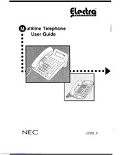
NEC ELECTRA ELITE User Manual (40 pages)
System Administration Terminal (SAT)
Brand: NEC
|
Category: Telephone System
|
Size: 1 MB
Table of Contents
Advertisement
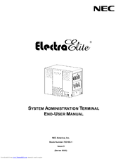
NEC ELECTRA ELITE User Manual (24 pages)
System Administration Terminal
Brand: NEC
|
Category: Telephone Accessories
|
Size: 7 MB
Table of Contents

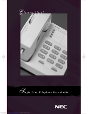

NEC ELECTRA ELITE User Manual (9 pages)
Single Line Telephone
Advertisement