Sign In
Upload
Manuals
Brands
BONFIGLIOLI Vectron Manuals
Control Unit
ACTIVE CUBE
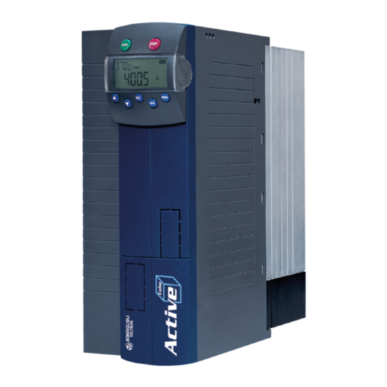
BONFIGLIOLI Vectron ACTIVE CUBE Inverter Manuals
Manuals and User Guides for BONFIGLIOLI Vectron ACTIVE CUBE Inverter. We have
6
BONFIGLIOLI Vectron ACTIVE CUBE Inverter manuals available for free PDF download: Manual, Applications Manual
BONFIGLIOLI Vectron ACTIVE CUBE Manual (138 pages)
PROFINET Communication module CM-PROFINET Frequency inverter 230 V / 400 V
Brand:
BONFIGLIOLI Vectron
| Category:
Control Unit
| Size: 11 MB
Table of Contents
Table of Contents
3
1 General Information about the Documentation
6
This Document
7
Obligation
8
2 General Safety Instructions and Information on Use
9
Designated Use
10
Residual Risks
11
Warning Information and Symbols Used in the User Manual
12
Personal Safety Equipment
13
Directives and Guidelines to be Adhered to by the Operator
14
Organizational Measures
15
The Five Safety Rules
16
Maintenance and Service/Troubleshooting
17
3 Introduction
18
Supported Configurations
19
Initialization Time
20
5 Assembly/Disassembly of the Communication Module
21
Disassembly
22
6 Description of Module and Commissioning
23
Alarm Messages
24
Operating Behavior in the Case of Bus Connection Failure
25
7 Setting the Process Data
26
Available Objects
28
8 Handling of Objects
29
Order ID
30
Error Message
31
Communication Procedure
32
Parameters, Data Set Selection and Cyclic Writing
33
Communication Examples
34
Handling of Index Parameters / Cyclic Writing
36
Example: Writing of Index Parameters
37
Example: Reading of Index Parameters
39
Parameter Access through Reading/Writing of Data Sets
40
Process Data Channel
42
PROFINET Output Sources (OUT-PZD X)
44
PROFINET Input Parameters (IN-PZD X)
45
Frequency Conversion PDP-Word to Internal Representation
47
Resetting Errors
48
9 Operation Without Motion Control
49
Object and Parameter Relationships
50
Functions of the Motion Control Interface (MCI)
54
Modes of Operation
55
Profile Position Mode
57
Profile Velocity Mode Pv
58
Table Travel Record Mode
59
Motion Control Mapping for PROFINET
60
Motion Control Override
61
11 Control of Frequency Inverter
63
Control Via Contacts/Remote Contacts
64
Device State Machine
66
Control Via State Machine
67
State Machine Diagram
69
Configurations Without Motion Control
72
Behavior in the Case of Transition 5 (Disable Operation)
73
Reference Value/Actual Value
74
Sequence Example
76
Motion Control Configurations
77
Velocity Mode [Rpm]
78
Sequence Example
81
Profile Velocity Mode [U/S]
83
Example Sequence
86
Profile Position Mode
87
Sequence Example
93
Homing Mode
95
Sequence Example
98
Table Travel Record Mode
99
Description
101
Sequence Example
106
Control Word
108
Bit
108
Move Away from Limit Switch Mode
108
Bit
109
Identification Value
110
Stop Axis with Ramp of Current Motion Block the Fre- Quency Inverter Remains in "Operation - Enabled" Status
110
Stop Axis with Ramp of Current Motion Block
110
Control Word
110
Halt
110
Axle Decelerated
110
Sequence Example
111
Electronic Gear: Slave
112
Target Position Reached
114
Master/Slave Position Correction
119
Sequence Example
121
Motion Control Configurations
123
Halt Bit
110
Bit 11
110
Status Word
110
Target Reached
110
12 Parameter List
124
Parameters
125
13 Appendix
127
Status Word Overview
128
Warning Messages
129
Application Warning Messages
130
Error Messages
131
Homing Modes
132
Conversions
134
Index
135
Advertisement
BONFIGLIOLI Vectron ACTIVE CUBE Manual (88 pages)
Modbus communication with CM-232/CM-485/CM-485T. Frequency Inverter 230 V / 400 V
Brand:
BONFIGLIOLI Vectron
| Category:
DC Drives
| Size: 2 MB
Table of Contents
Table of Contents
5
1 General Safety Instructions and Information on Use
7
General Information
7
Purpose of the Frequency Inverters
7
Transport and Storage
8
Handling and Installation
8
Electrical Connection
8
Information on Use
9
Maintenance and Service
9
2 Introduction
10
3 Installation/Disassembly of the Communication Module
11
Installation
11
Disassembly
12
4 Plug Assignment/Bus Termination/Cable
13
RS232 Module CM-232
13
RS485 Module
14
RS485 Module CM-485 DB9
14
RS485 Module CM-485 T
14
Bus Termination
15
5 Startup
16
General Information on Configuration
16
RS232 Module CM-232
18
Setting the Modbus Baud Rate and Parity
18
Setting the Modbus Address
18
RS485 Module CM-485
19
Setting the Modbus Baud Rate and Parity
19
Setting the Modbus Node Address
19
6 Modbus over Serial Line Protocol
20
Master/Slaves Protocol Principle
20
Addressing Rules
21
Message Description
21
Supported Function Codes
22
Function Code 3, Read 16-Bit Parameter
22
Function Code 6, Write 16-Bit Parameter
24
Function Code 100, Read 32-Bit Parameter
25
Function Code 101, Write 32-Bit Parameter
26
Function Code 8, Diagnostics
27
Exception Responses
29
Exception Codes
29
The Two Serial Transmission Modes
31
RTU Transmission
31
Character Format
31
Frame Description
31
Modbus Message RTU Framing
32
CRC Checking
32
ASCII Transmission
35
Character Format
35
Modbus Message ASCII Framing
35
LRC Checking
36
Monitoring Timing Function
37
Watchdog
37
7 Handling of Data Sets/Cyclic Writing
38
8 Modbus Message Examples
40
Modbus RTU-Message Examples
40
Function Code 3, Read 16-Bit Parameter
40
Function Code 6, Write 16-Bit Parameter
41
Function Code 100, Read 32-Bit Parameter
42
Function Code 101, Write 32-Bit Parameter
43
Function Code 8, Diagnostics
44
Modbus ASCII-Message Examples
45
Function Code 3, Read 16-Bit Parameter
45
Function Code 6, Write 16-Bit Parameter
46
Function Code 100, Read 32-Bit Parameter
47
Function Code 101, Write 32-Bit Parameter
48
Function Code 8, Diagnostics
49
9 ACT Inverter Control/Reference Value
50
Control
52
Control Via Contacts
52
Control Via Control Word of Statemachine
55
Behavior in Case of Quick Stop
60
Behavior in State-Transition 5
61
Control Via Remote Contacts
62
Reference Value
65
Reference Frequency
65
Reference Percentage
67
10 ACU Inverter Control/Reference Value
68
Control Via Contacts/Remote Contacts
70
Control Via State Machine
73
Behavior in Quick Stop
76
Behavior in Transition 5
77
Reference Value/Actual Value
78
11 Parameter List
80
Actual Value Menu (VAL)
80
Parameter Menu (PARA)
80
12 Annex
82
Warning Messages
82
Error Messages
83
ASCII Tabelle (0X00 - 0X7F)
85
BONFIGLIOLI Vectron ACTIVE CUBE Manual (76 pages)
Expansion Module EM-IO-03, Frequency Inverter 230V / 400V
Brand:
BONFIGLIOLI Vectron
| Category:
DC Drives
| Size: 1 MB
Table of Contents
General Points on the Documentation
3
Table of Contents
4
1 General Safety and Application Information
7
General Information
7
Proper Use
7
Transport and Storage
8
Handling and Positioning
8
Electrical Connection
8
Operation Information
8
Maintenance and Service
8
2 Introduction
9
3 Installation of the EM-IO-03 Expansion Module
10
General
10
Mechanical Installation
10
Electrical Installation
12
Circuit Diagram
12
Control Terminals
13
4 System Bus Interface
14
Bus Termination
14
Cables
15
Socket X410B
15
Baud Rate Setting/Line Length
16
Setting Node Address
16
Functional Overview
17
Network Management
17
SDO Channels (Parameter Data)
18
PDO Channels (Process Data)
19
Master Functionality
20
Control Boot-Up Sequence, Network Management
20
SYNC Telegram, Generation
22
Emergency Message, Reaction
23
Client SDO (System Bus Master)
24
Slave Functionality
25
Implement Boot-Up Sequence, Network Management
25
Boot-Up Message
25
Status Control
25
Process SYNC Telegram
26
Emergency Message, Fault Switch-Off
27
Server SDO1/SDO2
28
Communication Channels, SDO1/SDO2
30
SDO Telegrams (SDO1/SDO2)
30
Communication Via Field Bus Connection (SDO1)
32
4.10.2.1 Profibus-DP
32
4.10.2.2 RS232/RS485 with VECTRON Bus Protocol
32
Process Data Channels, PDO
34
Identifier Assignment Process Data Channel
34
Operation Modes Process Data Channel
35
Timeout Monitoring Process Data Channel
36
Communication Relationships of the Process Data Channel
37
Virtual Links
38
Input Parameters of the Txpdo's for Data to be Transmitted
41
4.11.5.2 Source Numbers of the Rxpdo's for Received Data
43
4.11.5.3 Examples of Virtual Links
44
Control Parameters
45
Handling of the Parameters of the System Bus
46
Utilities
48
Definition of the Communication Relationships
49
Production of the Virtual Links
50
Capacity Planning of the System Bus
51
5 Control Inputs and Outputs
53
Analog Input EM-S1INA
53
General
53
Configuration Voltage/Current Input
53
Characteristic
54
Operation Modes
54
Examples
55
Scaling
57
Tolerance Band and Hysteresis
58
Error and Warning Behavior
59
Adjustment
60
Filter Time Constant
60
Analog Output EM- S1OUTA (Voltage Output)
61
General
61
Operation Modes
61
Adjustment
61
Zero Adjustment and Amplification
62
Examples
62
Analog Output EM- S2OUTA (Current Output)
63
General
63
Operation Modes
63
Adjustment
63
Zero Adjustment and Amplification
64
Examples
64
Digital Output EM-S1OUTD
65
General
65
Operation Modes
65
Digital Inputs EMS2IND and EMS3IND
65
Fixed Reference Values and Fixed Value Switch-Over
65
Digital Inputs for Speed Sensor 2
66
Division Marks Speed Sensor 2
66
Actual Speed Source
67
Actual Value Comparison
67
Frequency and Percentage Reference Channel
68
Actual Value Display
68
Status of the Digital Signals
69
Motor Temperature
70
6 Parameter List
72
Actual Value Menu (VAL)
72
Parameter Menu (PARA)
72
7 Annex
75
Error Messages
75
Advertisement
BONFIGLIOLI Vectron ACTIVE CUBE Applications Manual (44 pages)
Brand:
BONFIGLIOLI Vectron
| Category:
DC Drives
| Size: 1 MB
Table of Contents
Table of Contents
2
1 General Information about the Documentation
4
This Document
4
Warranty and Liability
5
Obligation
5
Copyright
5
Storage
5
2 General Safety Instructions and Information on Use
6
Terminology
6
Designated Use
7
Misuse
7
Explosion Protection
7
Residual Risks
8
Safety and Warning Signs on Frequency Inverter
8
Warning Information and Symbols Used in the Operating Instructions
9
Hazard Classes
9
Hazard Symbols
10
Prohibition Signs
10
Personal Safety Equipment
10
Recycling
10
Grounding Symbol
10
ESD Symbol
10
Information Signs
11
Font Style in Documentation
11
Directives and Guidelines to be Adhered to by the Operator
12
Operator's General Plant Documentation
12
Operator's/Operating Staff's Responsibilities
12
Selection and Qualification of Staff
12
General Work Safety
12
Organizational Measures
13
General
13
Use in Combination with Third-Party Products
13
Transport and Storage
13
Handling and Installation
14
Electrical Connections
14
The Five Safety Rules
14
Safe Operation
15
Maintenance and Service/Troubleshooting
16
Final Decommissioning
16
3 Introductory Information about Winder Applications
17
Configurations for Winder Applications
17
Software Identification
17
Operating Behavior
18
Control Inputs and Outputs
19
Control Terminals
19
4 Applications
21
Example: Indirect Traction Control
21
Example: Dancer Control
22
Example: Unwinding at Constant Speed
23
5 Function Blocks
24
Dancer Control
24
General Control Parameters
24
Parameters for Limitation of Controller Output and Ramping
25
Behavior in an Emergency Stop or Stop
25
Parameters for Weighting and Inversion of the Controller Output
25
Output Values
26
Diameter Calculator
26
Parameters for both Operation Modes
26
Parameters for Operation Mode 1 - Sensor
28
Parameters for Operation Mode 10 - Estimation
28
Output Values
30
Actual Value Parameters from Diameter Calculation
31
Electronic Gear (Speed Setpoint)
31
Parameter
31
Output Values
32
Limitation of Web Tension (Tension Setpoint)
33
Calculation of Static Torque for Parameter 861
33
Compensation Calculator (Torque Compensation)
34
Compensation of System Losses
34
Compensation of Static Frictional Losses
34
Compensation of Dynamic Frictional Losses
35
Compensation of Acceleration Torque
36
Compensation of Constant Acceleration Torque
36
Compensation of Diameter-Dependent Acceleration Torque
37
Limit for Detection of Acceleration Process
38
Current Limitation
38
Output of Compensation Calculator
38
6 Overview of Sources
39
7 Actual Values
39
8 Parameter
40
BONFIGLIOLI Vectron ACTIVE CUBE Manual (64 pages)
Profibus-DP Communication module CM-PDPV1 Frequency Inverter 230V / 400V
Brand:
BONFIGLIOLI Vectron
| Category:
DC Drives
| Size: 1 MB
Table of Contents
Table of Contents
5
1 General Safety and Application Information
7
General Information
7
Proper Use
7
Transport and Storage
8
Handling and Installation
8
Electrical Connection
8
Operating Information
9
Maintenance and Servicing
9
2 Introduction
10
3 Installation/Disassembly of the Communication Module
11
Installation
11
Disassembly
12
4 Socket Connection/Bus Termination/Line
13
5 Baud Rate Setting/Line Length
14
6 Setting the Station Address
14
7 LED Indicators
15
8 Status Parameters
16
9 Error Behaviour
16
10 Setting PPO Structure
17
Configuration Process on the DP Master
18
11 Commands SYNC/FREEZE
20
12 Available Objects/Scanning Times
20
13 Handling of the Objects
23
Parameter Access Via Communication Channel PKW
23
Request Identification
24
Reply Identification
24
Fault Messages
24
Parameters, Data Set Selection and Cyclic Writing
25
Sequence of Communication
26
Examples of Communication
27
Parameter Access Via the DP-V1 Channel
29
Standard Mode
30
S7-Compatible Mode
31
Process Data Channel
32
Data Types of OUT/IN-Objects
32
Profibus Output Sources (OUT-PZD X)
34
Profibus Input Parameters (IN-PZD X)
35
Inverter Internal Notation
37
PZD1, Control Word/State Word
38
Control Via Contacts
39
Control Via State Machine
40
Behaviour in Quick Stop
44
Behaviour in Transition 5
45
Control Via Remote Contacts
46
PZD2, Reference Value/Actual Value
49
Actual Value Display of Profibus Data
51
14 Parameter List
54
Actual Values
54
Parameters
55
15 Annex
56
Warning Messages
56
Fault Messages
56
GSD File - BV
57
BONFIGLIOLI Vectron ACTIVE CUBE Applications Manual (42 pages)
Safe Torque Off
Brand:
BONFIGLIOLI Vectron
| Category:
DC Drives
| Size: 1 MB
Table of Contents
Table of Contents
3
1 General Information about the Documentation
5
Instruction Manuals
5
This Document
6
Warranty and Liability
6
Obligation
7
Copyright
7
Storage
7
2 General Safety Instructions and Information on Use
8
Terminology
8
Designated Use
9
Misuse
9
Explosion Protection
9
Residual Risks
10
Safety and Warning Signs at Frequency Inverter
10
Warning Information and Symbols Used in the User Manual
11
Hazard Classes
11
Hazard Symbols
11
Prohibition Signs
11
Personal Safety Equipment
11
Recycling
12
Grounding Symbol
12
ESD Symbol
12
Information Signs
12
Directives and Guidelines to be Adhered to by the Operator
13
Operator's General Plant Documentation
13
Operator's/Operating Staff's Responsibilities
13
Selection and Qualification of Staff
13
General Work Safety
13
Organizational Measures
14
General
14
Use in Combination with Third-Party Products
14
Transport and Storage
14
Handling and Installation
14
Electrical Connections
14
2.10.5.1 the Five Safety Rules
15
Safe Operation
15
Maintenance and Service/Troubleshooting
16
Final Decommissioning
16
3 Safety Instructions on Function „Safe Torque Off" (STO)
17
Approved Devices
18
4 Information of Risk Analysis and Risk Assessment
19
5 General Description of Safety Function
20
Integrated Safety Function
20
Functional Safety
20
Classification the Safety Requirement
20
6 Description of ACTIVE Cube Safety Function
21
Two-Channel Monitoring
22
Diagnosis Function and Enforced Dynamizing
24
Diagnosis Indicators
25
7 Requirements to be Met by Installation
26
Instructions on Installation of Safety Equipment
26
External Safety Control Equipment
27
External DC 24 V Power Supply
27
DC 24 V Power Supply by ACU
28
8 Requirements to be Met in Operation
28
9 Requirements to be Met by Acceptance Inspection
28
10 Application Examples
29
Direct Stop, Stop Category 0
30
Direct Stop with Feedback to PLC, Stop Category 0
31
Direct Stop, Stop Category 1
32
Direct Stop with Feedback to PLC, Stop Category 1
33
Internal DC 24 V Supply, Stop Category 1
34
Group Stop, Stop Category 1
35
Error Exclusion "Short Circuit" in the Cabinet
36
11 Checklist
37
12 Safety Function Test Report
38
13 STO Status (Diagnosis)
38
14 Index of Change
39
15 Index
40
Advertisement
Related Products
BONFIGLIOLI Vectron Agile VABus/TCP
BONFIGLIOLI Vectron ACTIVE CUBE Series
BONFIGLIOLI Vectron ACTIVE
BONFIGLIOLI Vectron Agile
BONFIGLIOLI Vectron AEC Series
BONFIGLIOLI Vectron AEC 401-19
BONFIGLIOLI Vectron AEC 401-21
BONFIGLIOLI Vectron AEC 401-23
BONFIGLIOLI Vectron AEC 401-25
BONFIGLIOLI Vectron AEC 401-33
BONFIGLIOLI Vectron Categories
DC Drives
Inverter
Control Unit
More BONFIGLIOLI Vectron Manuals
Login
Sign In
OR
Sign in with Facebook
Sign in with Google
Upload manual
Upload from disk
Upload from URL