
Related Manuals for Eneo INR-18N040005A


Summary of Contents for Eneo INR-18N040005A
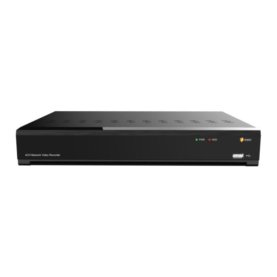
- Page 1 Full User Manual Network Video Recorder PoE, H.265, HDMI, VGA, SATA, w/o HDD INR-18N040005A INR-28N080005A INR-18N320005A Learn more about eneo IN series on our YouTube channel.
-
Page 2: Table Of Contents
TABLE OF CONTENT ABOUT THIS DOCUMENT ��������������������������������������������������������������������������������������������������������������������������������������������������������������������������������� 5 SAFETY INSTRUCTIONS ����������������������������������������������������������������������������������������������������������������������������������������������������������������������������������� 6 OPEN SOURCE SOFTWARE LICENSE INFORMATION ������������������������������������������������������������������������������������������������������������������������������������� 8 1 - PRODUCT OVERVIEW ��������������������������������������������������������������������������������������������������������������������������������������������������������������������������������10 1.1 - Rear Panel ................................................10 1.2 - Remote Controller ..............................................11 2 - INSTALLATION & CONNECTION ���������������������������������������������������������������������������������������������������������������������������������������������������������������12 2.1 - HDD Installation .............................................. - Page 3 5.3.4 - Combined Alarm ....................................................73 5.3.5 - PTZ Linkage ......................................................74 5.3.6 - Exception Alarm ....................................................75 5.3.7 - Alarm Schedule ....................................................76 5.3.8 - Voice Prompts ....................................................77 5.3.9 - Deterrence ......................................................80 5.3.10 - Siren ........................................................82 5.3.11 - Disarming ......................................................83 5.4 - AI ....................................................84 5.4.1 - AI Setup ........................................................84 5.4.2 - AI Recognition....................................................
- Page 4 8 - REMOTE ACCESS THROUGH THE WEB CLIENT ��������������������������������������������������������������������������������������������������������������������������������������206 8.1 - Basic System Environment Requirements ......................................206 8.2 - Web Plug in Downloading and Installation ....................................206 8.3 - Web Client Management ...........................................208 8.3.1 - Live View Page ....................................................208 8.3.2 - Playback Page ....................................................213 8.3.3 - Remote Setting ....................................................
-
Page 5: About This Document
ABOUT THIS DOCUMENT In this document you will find a comprehensive description of a specific series of devices, which we have prepared with great care and accuracy in order to provide you with a deep insight into the general functions and features that characterize this series of devices. However, you should be aware that the detailed characterization presented in this document is based on the general product line. -
Page 6: Safety Instructions
SAFETY INSTRUCTIONS Read the safety instructions and the operating instructions carefully before installing the product. Depending on the product type, individual points may be omitted. Mounting & Installation • Ensure that the intended mounting location is suitable for the respective product (e.g. in terms of weight). - Page 7 Operation • The devices may only be operated within the temperature and humidity ranges specified in the data sheet. • Sufficient ventilation must be provided to prevent overheating. This applies in particular to devices such as recorders and switches that can generate heat. •...
-
Page 8: Open Source Software License Information
• the product detail pages on the eneo website (www.eneo-security.com), • the eneo download portal (https://datacloud.videor.com/s/eneodownloadportal). In case that previous link is broken, the latest link to the eneo download portal can be found on the respective eneo product page at www.eneo-security.com. -
Page 10: Product Overview
1 - PRODUCT OVERVIEW 1.1 - Rear Panel No� Item Description Power Switch To turn on or turn off the power of the NVR DC Power Input Connect to the attached DC power adapter LINE IN Audio line input. Connect to audio input device, such as microphone, sound pick-up. AUDIO OUT Audio output. -
Page 11: Remote Controller
1.2 - Remote Controller Button Functions Numeric keys; Press number 1 to 9 to display channel 1 to 9 directly. 0 to 9 Press combination of numbers quickly to display the channel lager than 9. Press to switch the channel display layout among multiple display modes Press to display the Task Bar while in live view;... -
Page 12: Installation & Connection
2 - INSTALLATION & CONNECTION 2.1 - HDD Installation Depending on the NVR you have purchased, the hard disk drive (HDD) may be included in the full package. If it is not pre-installed, follow the installation instructions on this user manual. Do NOT install or uninstall the HDD while the NVR is powered on CAUTION: Installation... -
Page 13: Connection Diagram
2.2 - Connection Diagram NOTE: Above connection diagram is for illustration purpose only. The interfaces in your actual product may vary with models. 2.3 - Power Supply Connection CAUTION: Use the power supply attached or specified by the manufacturer only. Contact your local dealer if any problem with the power supply is found. -
Page 14: Common Operations
3 - COMMON OPERATIONS 3.1 - Using the supplied mouse A - Left Button • Click to select menu options. B - Right Button • During live viewing in split- • Click once to open the Taskbar screen view, double-click on the Live Viewing screen. -
Page 15: Password
3.3 - Password Proper configuration of all passwords & other security settings is the responsibility of the installer and/or end-user. 3.3.1 - Password Generation For the first time when you run the NVR, you must be required to set your own password immediately in order to protect your privacy. -
Page 16: Password Reset
3.3.2 - Password Reset If you forget your password, you will be unable to login the system, reset your password with below methods: 3.3.2.1 - Reset with password recovery questions If you had enabled the password recovery questions in 3.3.1. Password Generation, you are able to reset your password with security questions. - Page 17 3.3.2.3 - Hard Reset If you are unable to reset the password with any one of the methods of A, B and C, you can try to hard reset your NVR if there is a Reset button on the rear panel. Press and hold 10 seconds on the button with a small pin till the NVR beeps.
-
Page 18: Nvr Starting
4 - NVR STARTING UP 4.1 - Start Wizard For the first time when your run this NVR, you may need to configure the Startup Wizard which will help to configure the system and get your NVR works properly and quickly. Log in the system and click the Start Wizard to proceed to the next step. - Page 19 Port http/https/rtsp: This is the port that you will use to log in remotely to the NVR (e.g. using the Web Client), or the NVR will be allowed to transmit real-time streaming to other device (e.g. using a streaming Media player.).
-
Page 20: Date/Time
4.1.2 - Date/Time This menu allows you to configure the Date, Time, Date Format, Time Format, Time Zone, NTP and DST. Date/Time Click on the calendar icon to set the current system date. Date: Click on the calendar icon to set the system date. -
Page 21: Ip Camera
4.1.3 - IP Camera Add IP cameras to the NVR in this section. 4.1.3.1 - Connect IP Camera to NVR PoE Ports IP cameras will get online automatically if the IP cameras are connected to the PoE ports on the rear panel. - Page 22 4.1.3.2 - Add IP Camera to PoE NVR from LAN If you want to add an IP camera to the PoE NVR from LAN, please make sure your NVR is well-connected to the LAN, and the IP camera you want to add is in the same network segment with your NVR. 1.
- Page 23 4.1.3.3 - Add IP Camera to PoE NVR from Internet If you want to add an IP camera to the PoE NVR from internet, please make sure your NVR is well- connected to internet. 1. Click the edit icon in the channel you want to add, and then click the drop-down arrow next to Switch Mode to select Manual and click OK to save.
-
Page 24: Disk
4.1.4 - Disk HDD must be formatted If it is installed in the NVR for the first time. Select the HDD and then click Format HDD button to format the HDD. Overwrite: This instructs your NVR to overwrite the oldest video files as the hard drive becomes full. You also have the option of selecting the amount of days for recordings to be kept before they are overwritten. -
Page 25: Mobile
4.1.6 - Mobile If your NVR come with a P2P ID, you can scan the QR code with your mobile app to view the NVR remotely. 4.1.7 - Summary You can tick the system summary information you had set in the start wizard and finish the wizard. Tick “Don’t show the Wizard after start.”... -
Page 26: Live View Screen Overview
4.2 - Live View Screen Overview For the first time when your run this NVR, you may need to configure the Startup Wizard which will help to configure the system and get your NVR works properly and quickly. 1 – Channel No. 2 –... -
Page 27: Definitions Of On Screen Icons & Messages
4.2.1 - Definitions of On screen Icons & Messages Status Icons Channel Abnormal Message Icon Meaning Message Meaning The camera is being recorded currently No Camera No camera is added to this channel. You can click the add icon to add a new camera. A motion alarm is happening Failed to The added camera is off-lined or lost connection. -
Page 28: Taskbar
4.2.3 - Taskbar In the Taskbar, you are able to enter the system menu, start playback and change the live view display, etc. Icon Meaning Click to pop up the Start Menu Click to display 4/9/12/16 channels in live view screen Click to display 20/25/36 channels in live view screen Click to choose more display layouts in live view screen Click to start viewing channels in a sequence. -
Page 29: Start Menu
4.2.5 - Start Menu With the Start menu, you can switch user, search & playback, enter system setup menu, lock & unlock the screen, shut down, reboot & logout the system. Item Description To switch user. To enable multi-user, please view admin on 5.7.2. -
Page 30: Fisheye Camera
4.2.6 - Fisheye Camera After a fisheye camera is added to the device and the device goes online, the fisheye operation icon is displayed in the shortcut menu of the preview channel area and the playback menu. You can click the button to open the fisheye-mode operation page. -
Page 31: Alarm Notification Panel
4.2.7 - Alarm Notification Panel The Alarm Notification Panel displays thumbnails of alarm events that have occurred. Events are color-coded according to the event type. Use the mouse scroll wheel to scroll up and down (place the mouse cursor over the notification panel first). Click the play button next to or over the thumbnail to play the event. -
Page 32: System Setup
5 - SYSTEM SETUP You are able to configure the NVR for Channel, Record, Alarm, Network, Device, System, AI, AI Scenario from Start Menu → Setup. 5.1 - Channel In this section, you are able to manage the camera connection, live view display, camera’s image, PTZ setup, video cover, motion setup, and more. -
Page 33: Channel
5.1.1 - Channel You’re able to add and delete IP cameras in this menu. If your NVR comes with PoE ports, you’re able to check the PoE power consumption here. 5.1.1.1 - IP Channels To add or delete IP cameras here. If your NVR comes with PoE ports, please go to 5.1.1.1.1 PoE NVR Connection. - Page 34 Edit: To edit the Switch mode, PoE mode, network parameters, user name and password for individual camera. State: Show the connection status of the camera. If the camera is successfully connected, the state will be displayed with a green icon If the camera failed to connect, the state will be dis- played with a grey icon...
- Page 35 Default Password To configure the default user name and password of Private, ONVIF and RTSP protocol connection. Default password is “admin”. Please note, if the user name and password of the camera you added is not same with the default values, you may need to input the user name and password each time after the NVR restarting.
- Page 36 5.1.1.1.1.2 - Connect External Cameras from LAN or Internet If you want to connect to an IP camera from LAN or internet, please make sure your NVR is well- connected to the LAN and or internet. If your NVR come with PoE ports, you need to change the PoE Switch Mode to be manual firstly.
- Page 37 Alias: To define the camera ID title you want to display in the live view screen. Port: Camera communication port. Protocol: To select the connection protocol. Bind channel: To determine which channel you want to add the camera. Click Add button. 5.
- Page 38 5.1.1.1.1.2.3 - Add Cameras from Other NVR in the LAN The NVR allows to add cameras from other NVRs in the local network. 1. Click Search button, all available devices in the LAN will be displayed. There is an edit icon displayed if the device is an NVR.
- Page 39 5.1.1.1.1.2.4 - Add Cameras from Internet If your NVR is connected to internet, you’re able to add cameras from internet with WAN IP address. 1. Click Add button in the search page. 2. Input the IP address or domain name, port, protocol, user name &...
-
Page 40: Live
5.1.2 - Live To configure camera parameters, including channel name, color, date & time format, refresh rate, etc. Convert: To hide the camera images in live view. If the covert is enabled, only live view images will be hidden. Recording images won’t be affected. Enable this if your NVR and TV is in a public area (shop, warehouse, etc.), but you don’t want others to see an image from the camera. - Page 41 Channel: Select a channel to edit Channel Name: Give a name to the camera Date Format: To choose a date format Time Format: To choose a time format Refresh Rate: Choose the correct refresh rate Show Name: To show or hide camera name Show Time: To show or hide date and time Alpha: Adjust the text transparency This allows you to adjust how visible the OSD (camera name, date &...
-
Page 42: Image Control
5.1.3 - Image Control This menu allows you to control image settings for supported IP cameras. If the camera is connected to the NVR with ONVIF protocol, it might be not supported to configure. Setup: Click icon into the setup page. Channel: Choose a channel to configure. - Page 43 Back Light: When the surrounding illumination and the object have large differences in brightness, you can enable the exposure compensation to get a better image. • WDR/DWDR: Images produced by wide dynamic range (WDR) function sensors can have proper exposure on both the darker and lighter parts of the image, giving more detail across a wider dynamic range between the shadows and highlights by brightening dark areas and darkening bright areas.
- Page 44 5.1.3.1 - Full Color Camera Settings If there is a full color camera connected to the NVR, an Image Setting option is displayed under the Image Control setting page. Full color camera includes not only IR LEDs, but also white light LEDs. You’re able to determine the operating mode of the lights: •...
-
Page 45: Ptz
5.1.4 - PTZ This menu allows to configure the PTZ (Pan/Tilt/Zoom) settings for the speed dome cameras. Channel: Channel name Signal Type: If your PTZ camera is connected to the RS485 port, then choose “Analog”, otherwise choose “Digital”. Following items are available only for Analog PTZ only: Protocol: Choose the communication protocol between the PTZ capable camera and NVR. - Page 46 5.1.4.1.1 - Controlling Your MFZ Camera You’re able to adjust the optical lens to zoom in or zoom out if a MFZ (Motorized Focus & Zoom) camera is connected. In live viewing, click the left button of your mouse on the MFZ camera to pop up the Camera Quick Toolbar.
- Page 47 5.1.4.1.2 - Controlling Your PTZ Camera In live viewing, click the left button of your mouse on the PTZ camera to pop up the Camera Quick Toolbar. Click the PTZ button to enter PTZ control panel. Mode: To control the PTZ camera by PTZ, Preset, Line Scan, Watch Mode, Tour and Pattern Scan. Directional Buttons: Click and hold the directional buttons to move the camera in the direction selected.
- Page 48 5.1.4.1.2.1 - Controlling PTZ In this section, you’re able to control the Pan/Tilt/Zoom and more. 1 – Select PTZ mode. 2 – Click the directional buttons to move the camera 3 – To adjust the speed to pan or tilt. 4 –...
- Page 49 5.1.4.1.2.2 - Preset Position In this section, you’re able to configure the preset positions. A preset position is a particular position within the image that you would like the camera to focus on. Up to 255 different preset positions can be created.
- Page 50 5.1.4.1.2.3 - Watch Mode Watch mode allows the camera to perform a preset action when there is no any operation to the camera, such as moving to a preset position, starting cruise, etc. 1 – Select the Watch Mode. 2 – Set the time interval. It means the length of time that must elapse before the watch mode is taken action.
- Page 51 5.1.4.1.2.5 - Tour With the Tour function, you’re able to configure maximum 4 tracks of auto cruise by choosing different preset positions. 1 – Select Tour mode. 2 – Select a track. Maximum 4 tracks available. 3 – Set the time interval. It means the length of time that the camera will stay in each preset position.
- Page 52 5.1.4.1.2.6 - Pattern Scan With the Tour function, you’re able to configure maximum 4 tracks of auto cruise by choosing different preset positions. 1 – Select Pattern Scan mode. 2 – Select a track. Maximum 4 tracks available. 3 – Adjust the speed control to alter how fast or slow the camera will pan or tilt.
-
Page 53: Pricavy Zone
5.1.5 - Pricavy Zone This function can obscure all or part of your image for privacy (you can create up to 4 privacy masks per camera). Areas obscured by a mask won’t be shown live or recorded. Channel: Select a camera that you would like to edit. -
Page 54: Motion Detection
5.1.6 - Motion Detection This menu allows you to configure motion parameters. When motion has been detected by one or more cameras, your NVR will alert you to a potential threat at your home. It does this by sending you an email alert with an attached image from the camera to use as a reference (if this option is enabled) and/or sending push notifications via the mobile app. - Page 55 Motion Detection Area Setup: Click icon into the setup page. 1. The whole screen is marked for motion detection (red blocks) as default. Click Clear All to delete all the default detection area. 2. To create a new detection area, press and hold the left mouse button to select the cell or square that you want to start at, then click and drag to select the area that you want to...
- Page 56 Buzzer: When motion is detected, you can enable the NVR’s buzzer to alert you for a predetermined amount of time. Click the drop-down menu to select a time. Alarm Out: If your NVR or IP camera supports to connect external replay output devices, the system can send an alert message to the external alarm devices.
-
Page 57: Pir
5.1.7 - PIR This menu allows you to configure PIR (passive infrared motion detector) parameters. When PIR alarm has been detected by one or more cameras, your NVR will alert to you a potential threat. It does this by sending you an email alert with an attached image from the camera to use as a reference (if this option is enabled) and/or sending push notifications via the mobile app. - Page 58 5.1.7.1 - PIR Alarm Settings Click the Alarm button to change options for alarm notifications and more. Buzzer: When PIR alarm is detected, you can enable the NVR’s buzzer to alert you for a predetermined amount of time. Click the drop-down menu to select a time. Alarm Out: If your NVR or IP camera supports to connect external replay output devices, the system can send an alert message to the external alarm...
- Page 59 Post Recording: This option instructs your NVR to record for a set time after an event has occurred. Show Message: When the detection is triggered, the alarm icon will appear on screen. Send Email: An email alert will be sent when alarm event is detected.
-
Page 60: Roi
5.1.8 - ROI Regions of Interest (ROIs) are selected regions for special attention in the video area. This function aims to improve the image encoding quality of the selected regions and reduce the encoding quality outside the selected regions, so as to ensure the image sharpness of the regions for special attention under the condition of constant bitrate. -
Page 61: Record
5.2 - Record The recording configuration options are available in the Record and Capture menus accessible from the Main Menu. From here, you can access and change the recording frame rate & resolution and recording schedule for each camera connected. You can also enable and set a schedule for your NVR to take a snapshot each time when an event occurs. - Page 62 Bitrate: This parameter corresponds to the speed of data transfer that the NVR will use to record video. Recordings that are encoded at higher bitrates, will be of better quality. For cameras that monitor medium to high traffic areas, increase the bitrate to add more detail to the camera’s image. Just be aware this will increase the bandwidth required.
-
Page 63: Record
5.2.2 - Record This menu allows you to configure the recording parameters for each channel. 5.2.2.1 - Recording Configuration Record Switch: Check to enable the recording in this channel. Stream Mode: By default, your NVR will record both Mainstream and Substream video (known as Dual-stream). - Page 64 5.2.2.2 - Recording Schedule This menu allows you to specify when the NVR records video and defines the recording mode for each channel. The recording schedule lets you set up a schedule like, daily and hourly by normal (continuous) recording, motion recording, I/O alarm recording & PIR recording (if your camera supports). By default, the NVR is set to constantly record in 24-hour 7 days.
-
Page 65: Capture Images
5.2.3 - Capture Images You can enable and set a schedule for your NVR to take a snapshot each time an event occurs. It helps to find alarm events quickly and can also be used for timelapse photography. NOTE: The maximum resolution of captured image is 1920x1080 5.2.3.1 - Capture Configuration Auto Capture: When enabled, your NVR will take a snapshot each time an event occurs. - Page 66 5.2.3.2 - Capture Configuration You must create a capture schedule so your NVR can take snapshots when an event has occurred or if you want to take snapshots using a time interval (every 5 seconds, for example). 1. Choose a Channel you want to set. 2.
-
Page 67: Alarm Settings
5.3 - Alarm Settings In this section, you can configure the alarm actions when event occurs. 5.3.1 - Motion Alarm Buzzer: When motion is detected, you can enable the NVR’s buzzer to alert you for a predetermined amount of time. Click the drop-down menu to select a time. Alarm Out: If your NVR or IP camera supports to connect external replay output devices, the system can send an alert message to the external alarm... - Page 68 FTP Picture Upload: Click the checkbox to copy snapshots to your ftp server when the detection is triggered. FTP Video Upload: Click the checkbox to copy videos to your ftp server when the detection is triggered. Picture to Cloud: Click the checkbox to copy snapshots to the cloud via Dropbox or Google Drive when the detection is triggered.
-
Page 69: Pir Alarm
5.3.2 - PIR Alarm Buzzer: When PIR is detected, you can enable the NVR’s buzzer to alert you for a predetermined amount of time. Click the drop-down menu to select a time. Alarm Out: If your NVR or IP camera supports to connect external replay output devices, the system can send an alert message to the external alarm devices. - Page 70 Picture to Cloud: Click the checkbox to copy snapshots to the cloud via Dropbox or Google Drive when the detection is triggered. Video to Cloud: Click the checkbox to copy videos to the cloud via Dropbox or Google Drive when the detection is triggered.
-
Page 71: I/O Alarm
5.3.3 - I/O Alarm If your NVR or the connected camera has alarm input function, you will need to configure the settings to make the connected sensor works probably. Alarm In: Alarm input channel • Local: Alarm input devices connected to NVR •... - Page 72 Post Recording: This option instructs your NVR to record for a set time after an event has occurred. For most instances, the default selection will be suitable, however, you can change this if you wish. Show Message: When the detection is triggered, the alarm icon will appear on screen.
-
Page 73: Combined Alarm
5.3.4 - Combined Alarm Combined Alarm function allows to set a combination of 2 alarm types. The NVR will only alert when both the alarm types in the combination are triggered in the same time. This would help to minimize the false alarm rate. -
Page 74: Ptz Linkage
Show Message: When the detection is triggered, the alarm icons will appear on screen. Send Email: An email alert will be sent when alarm event is detected. Tick the checkbox if you want to disable this. FTP Picture Upload: Click the checkbox to copy snapshots to your ftp server when the detection is triggered. -
Page 75: Exception Alarm
5.3.6 - Exception Alarm The system allows to set the abnormal events that you want the NVR to inform you. Event Type: There are three event types that your NVR will detect as an exception: • No Space on Disk: no space left on the hard drive. •... -
Page 76: Alarm Schedule
5.3.7 - Alarm Schedule You are able to set the schedule individually for Alarm out, Push Notification, FTP Upload, Cloud Upload, Buzzer and Voice Prompts. The schedule is set to enable 24 hours 7 days, you can change accordingly. 1. Select the channel you want to set the schedule. 2. -
Page 77: Voice Prompts
5.3.8 - Voice Prompts If your NVR or IP camera supports the voice prompt function and has a built-in or external speaker, you can set a customized alert voice when an alarm event occurs. 5.3.8.1 - Voice File Management You can create and delete voice files in this section. 5.3.8.1.1 - Creating Voice Files The system provides 3 different methods to create customized voices: •... - Page 78 Local Conversion: The system supports to convert your plain texts into an audio file by local algorithm. Choose Local Conversion model, and then input the name of the file & plain text. Click Import button, the system will convert the text you input into a voice file and save to the NVR storage.
- Page 79 5.3.8.2 - Loop Management The system allows to play a continuous loop of the voices in a certain period of time. 1 – Select the play device. 2 – Choose a voice file. 3 – Set the time period. 4 – Click play button to start the audition.
-
Page 80: Deterrence
5.3.9 - Deterrence This menu allows you to configure the action of built-in white lights (also known as “spotlights”) and speaker of the deterrence cameras when an alarm event is detected. Setup: Click button to enter configuration page. • Light: Click the drop-down menu to enable the camera’s white light. - Page 81 Schedule: Click button to configure the deterrence schedule: • When the camera is connected to the NVR with client port, the schedule interface might be displayed as adjacent image By default, the white lights will not trigger between and 04:30 p.m. and 06:30 a.m., however you can change this according to your needs.
-
Page 82: Siren
5.3.10 - Siren If the camera connected to the device has a built-in speaker, you can set the siren-related parameters in this module. Channel: Select the switch channel. Enable: Used to set whether to enable the siren function. Siren Type: Used to select the siren audio file. By default two audio files are provided. -
Page 83: Disarming
5.3.11 - Disarming After the one-click disarming function is enabled, you can cancel the response of the device to various alarms. On this page you can set the relevant parameters including the disarming switch, channel, type, and schedule. Note: The Exception system alarms are not controlled by one-click disarming. Disarming: Used to set whether to enable the one- click disarming function. -
Page 84: Ai Setup
5.4 - AI Artificial Intelligence (AI) is an advanced function for the system to detect varies of alarm events based on face detection, human detection and vehicle detection technology with AI powered IP cameras and take actions accordingly. You will see this section if your NVR has AI capacity. 5.4.1 - AI Setup In this section, you will able to activate the AI functions and let them work properly according to your requirements. - Page 85 Channel: to choose the channel you want to set. Snap Mode: select how snapshots containing a recognized face will be captured. This can affect the number of facial recognition notifications that you will receive: • Realtime Mode: the camera tracks and captures the face of someone entering and leaving the facial detection area.
- Page 86 Rule Kind: Rect (rectangular) and Line (linear):098 • If you choose Rect mode, you can choose Full Screen, the entire view of the camera is enabled for face detection as the detection area, or you can choose Customize to adjust the size of rectangular to focus the detection in a certain area.
- Page 87 Switch: Tick the checkbox to enable the human & vehicle detection. Setup: Click setup button for further settings: Channel: to choose the channel you want to set. Snap Mode: select how snapshots containing a recognized object will be captured. This can affect the number of notifications that you will receive: •...
- Page 88 Detection Area: If you choose Full Screen, the entire view of the camera is enabled for human and/or vehicle detection as the detection area, or you can choose Customize to adjust the size of rectangular to focus the detection in a certain area. Dynamic Marking: If Disable is selected, the green tracking frame that surrounds a detected object will not be visible during Live View mode and playback.
- Page 89 3. Choose one of the Rule Number. It is the number of PID area. Maximum 4 areas you can set for PID function. 4. To enable the detection in Rule Switch. 5. Choose a Rule Type: • A→B: Camera will only detect the action from side A to side B; •...
- Page 90 1. Select the channel you want to configure. 2. Select the detection targeted object. 3. Choose one of the Rule Number. It is the number of LCD lines. Maximum 4 lines you can draw. 4. To enable the detection in Rule Switch. 5.
- Page 91 1. Select the channel you want to configure. 2. Select the detection targeted object: • Motion: All moving subjects will be detected by the system • Person: Only human beings will be detected • Vehicle: Only vehicles will be detected. 3.
- Page 92 5.4.1.6 - HM (Heat Map) Heat Map is a video analytics tool to provide a graphic overlay in the form of a heat map displaying the area and frequency of motion detected. This is especially useful for retail businesses to track customer movement to better understand consumer behavior.
- Page 93 5.4.1.7 - CD (Crowd Density Detection) Crowd density detection is based on face detection technology, which is used to detect crowd gathering to maintain a controllable order in certain area. When the total number of detected people in a certain area exceeds the pre-set allowed number, the system will send an alert.
- Page 94 5.4.1.8 - QD (Queue Length Detection) Queue length detection is used to detect the status of a queue, including its length and staying time. Switch: To enable or disable the queue length detection function. Sensitivity: Adjust the sensitivity level. The higher the number, the more sensitive the detection will be. Setup: Click to configure the detection conditions.
- Page 95 5.4.1.9 - LPD (License Plate Detection) License Plate Detection function, also called "Automatic License/Number Plate Recognition (ANPR)", helps to detect and record the license plate number. Switch: To enable or disable the crowd density detection function. Setup: Click to configure the detection conditions. 1.
- Page 96 5. Choose one of the license plate types: • European license plate: mainly used in European countries. • American license plate: mainly used in United States. 6. Choose the detection mode: • Static Mode: all vehicles' license plates in the camera's field of view will be analyzed. •...
- Page 97 Detection Type: • Baby Crying Sound: Tick to enable baby crying detection. • Dog Barking: Tick to enable dog barking detection. • Gunshot: Tick to enable gunshot detection. Click Save to save your settings. 5.4.1.11 - SOD (Stationary Object Detection) Stationary Object Detection function detects the objects left over or lost in the pre-defined region, such as the baggage, purse, dangerous materials, etc., and a series of actions can be taken when the alarm is triggered.
- Page 98 4. Use your mouse to click 4 points in the camera image to draw a virtual region. The sharp of the region should be a convex polygon. Concave polygon will be not able to save. 5. Click Save to save your settings. 6.
- Page 99 5.4.1.12 - Sound Detection With the sound detection, it will alert you when your NVR detects audio that matches or exceeds the set trigger level, and some certain actions can be taken when the alarm is triggered. Switch: enable or disable sound detection. Rise: enable or disable sound rise detection.
- Page 100 5.4.1.13 - Video Tampering Video Tampering detects the occlusion of camera images, and some certain actions can be taken when the alarm is triggered. Switch: Enable or disable the function Sensitivity: The sensitivity level is from 1 to 6, with a default value of 3. Higher sensitivity will be easier to trigger the detection.
- Page 101 5.4.1.14 - Schedule You can configure the recording schedule for AI detection functions. The interface might be different vary with different camera firmware. Interface A 1. Choose the channel you want to set. 2. Click on the mode radio button to choose one of the detection functions 3.
-
Page 102: Ai Recognition
5.4.2 - AI Recognition With the face detection & license plate detection functions, the system supports to recognize faces and vehicle license, you would need to configure the recognition algorithm model and manage the database. 5.4.2.1 - Model Configuration To choose the face recognition AI algorithm model. 1 –... - Page 103 4. Newer version (with bigger digital sequence) is preferred to be selected due to its algorithm optimization and database update. 5. Multiplex models with same version are allowed & recommended to be enabled. This would help to decrease the analysis loading on a single NVR or camera and accelerate the recognition.
- Page 104 5.4.2.2 - Face Recognition Database Management You're able to create and manage the face profiles (database) to classify different people into different groups in order to quickly identify people in remote and realize intelligent alarm beforehand. There are 3 default groups: •...
- Page 105 5.4.2.2.1 - Create Face Profile from Local Storage Device This section will show how to create face profiles from face images that have been captured and stored on your NVR. 1 – Click the Edit button of the group that you would like to create face profiles for.
- Page 106 8 – Click on a face image, then enter their identification details, such as the person's name and age. By default, each face image is given a face ID as its name. 9 – When finished, click Import button. The face profile is now created and assigned to the group.
- Page 107 5 – Edit the face profile of the people. 6 – Click setup button to configure the voice prompt for the person. View more on 5.3.9. Voice Prompts to learn how to configure this function. NOTE: The voice file you import here takes effect only to this person.
- Page 108 5.4.2.2.3 - Create Bulk Face Profile from External Storage Device If you want to create a batch of face profiles at once, please proceed as below: 1. Click the Edit button of the group that you would like to create face profiles for.
- Page 109 8. Edit the cells according to your actual conditions as illustrated as below: NOTE: If you input a number uninterruptedly more than 11 digits in a cell, the system will dis- play the number in scientific notation, e.g., "1.23457E+11". If so, you would need to adjust the format of the column to be "Text"...
- Page 110 5.4.2.2.4 - Edit Face Profiles If you want to edit or delete a face profile, please proceed as below: 1. Click on the edit button of the group you want to edit 2. In the group edit page, you're able to execute below operations: •...
- Page 111 5.4.2.3 - License Plate Management You're able to create and manage the vehicle license profile (database) to classify different vehicles into different groups in order to quickly identify vehicles in remote and realize intelligent alarm beforehand. There are 3 default groups: •...
- Page 112 3 – Channels: All channels are set to search by default. You can specify the cameras you want to search on. 4 – Use the calendar to specify the date range. 5 – Choose the day duration, and then use the arrow buttons to quickly display license plate images from the previous or next day(s).
- Page 113 5.4.2.3.2 - Create License Profiles Manually This section will show how to create vehicle manually. 1 – Click the Edit button of the group that you would like to create vehicle license profiles for. 2 – Click the Import button. 3 –...
- Page 114 5.4.2.3.3 - Create Bulk License Profiles If you want to create a batch of license profiles at once, please proceed as below: 1. Insert your USB flash drive into the USB port of the NVR. 2. Click the Edit button of any one of groups where there is at least one vehicle license profile exists.
- Page 115 Columns • G: ID number of the owner of the vehicle • A: License number of the vehicle • H: Phone number of the owner of the vehicle • B: Color of the vehicle • I: Occupation/Job/Career of the owner of the •...
- Page 116 12. Now you can see a list of license number as illustrated below. Click on one of the license numbers, the detailed information will be list on the right side. Click Import button to import the license profiles into the NVR and click Exit to finish. 5.4.2.3.4 - Edit License Profiles If you want to edit or delete a face profile, please proceed as below: 1.
- Page 117 3. If you want to delete, move or export license profile(s), please proceed as below: Tick the checkbox to select the license profile firstly: • If you want to delete, click Delete button and confirm to delete the selected license profile(s). •...
-
Page 118: Ai Alarm Settings
5.4.3 - AI Alarm Settings In this section, you can configure the alarm actions when event occurs. 5.4.3.1 - FR (Face Recognition) Alarm Settings To configure alarm actions for different groups when faces detected. Enable Alarm: Tick the checkbox of the group(s) you want to enable alarm function. If the checkbox isn't enabled, no actions specified for the group such as alarm notifications will be actioned by your NVR. - Page 119 Latch Time: To configure the external alarm time when the detection is triggered. Face Capture: Configure whether the snapshot of the recognized face will be saved to the face database on your NVR. Leave this option enabled so more facial images can be added to profiles later to improve the accuracy of face recognition.
- Page 120 5.4.3.2 - AD (Attribution Detection) Alarm Settings Attribute detection is a function to detect people's facial features and send an alarm according to the settings. Alarm Type: Select an alarm trigger condition: • No Mask: When a person is detected not wearing a face mask, the NVR will send an automated alert •...
- Page 121 Send Email: An email alert will be sent when alarm event is detected. Click the checkbox if you want to disable this. Full Screen: Click the checkbox to view the camera full-screen in Live View mode when the detection is triggered.
- Page 122 Recognized License Number Number in License Profile Fault Tolerance Recognition Result AB123C AB-123-C ≤2 characters True AB123C AB-123-C ≤0 or 1 character False A8I23C AB123C ≤2 characters True A8I23C AB123C ≤0 or 1 character False B594SB B734KB ≤3 characters True B594SB B734KB ≤2 character...
- Page 123 Copy: Use the Copy function to apply all settings to the other connected cameras. Default: Click Default to revert to default settings. Save: Click Save to save settings. Alarm Schedule: Click setup button configure the schedule of when actions specified for the group will take effect.
- Page 124 Click button, click the Record Channel checkbox to enable recording. Click the checkbox in front of the channel number to select all channels or click on the individual camera number that you want to trigger for recording. Post Recording: This option instructs your NVR to record for a set time after an event has occurred. For most instances, the default selection will be suitable, however, you can change this if you wish.
- Page 125 Buzzer: When alarm event is detected, you can enable the NVR's buzzer to alert you for a predetermined amount of time. Click the drop-down menu to select a time. Alarm Out: If your NVR or IP camera supports to connect external replay output devices, the system can send an alert message to the external alarm devices.
-
Page 126: Statistics
5.4.4 - Statistics Your NVR can retrieve and present statistical data relating to the detection of objects when related AI detection is enabled on the camera. 5.4.4.1 - FR (Face Recognition) Statistics Your NVR can retrieve and present statistical data relating to the detection of faces when the Face Recognition is enabled on the camera. - Page 127 5.4.4.2 - PD & VD (Human & Vehicle) Statistics Your NVR can retrieve and present statistical data relating to the detection of objects when the Human & Vehicle video analytic is enabled on the camera. The bar chart displays the number of humans and/or vehicles that were detected during a particular time.
- Page 128 5.4.4.4 - HM (Heat Map) Statistics Your NVR can retrieve and present statistical data relating to the detection of objects when the Heat Map video analytic is enabled on the camera. The color map gives you a visual display showing the area and frequency of motion detected.
-
Page 129: Network
5.5 - Network This menu allows you to configure network parameters 5.5.1 - General Settings To configure the network connection parameters here. 5.5.1.1 - General To configure the network connection parameters here. If you connect to a router which allows to use DHCP (Dynamic Host Configuration Protocol), please tick the checkbox of DHCP. - Page 130 Web Compatibility Mode: If you are failed to login the NVR webpage with https protocol, enable the compatibility mode and try again. Otherwise, keep it disabled. If your NVR comes with PoE ports, you will see the Internal Interface as shown: PoE DHCP Server: Tick the checkbox to enable DHCP service.
- Page 131 5.5.1.3 - SNMP SNMP (Simple Network Management Protocol) is an Internet Standard protocol for collecting and organizing information about managed devices on IP networks and for modifying that information to change device behaviour. With the SNMP, you are allowed to connected the NVR with 3rd party network management platform and acquire the NVR information, such as firmware version number, device type, resolution, frame rate, and etc.
- Page 132 NOTE: The Wi-Fi connection function is not a universal feature for all models. Inquiry your local dealer before using this feature. Before proceeding, disconnect the Ethernet cable from your NVR's Ethernet port (if connected). 1. Tick the checkbox of Enable to activate the Wi-Fi connection. 2.
- Page 133 http/https/rtsp: This port is mostly used to log into your NVR via webpage or 3rd party streaming player by rtsp protocol. If the default port number (80) is used by other devices in the network, you may need to change it. Client Port: This is the internal port that your NVR will use to send information through.
-
Page 134: Ddns
5.5.2 - DDNS This menu allows you to configure DDNS settings. The DDNS provides a static address to simplify remote connection to your NVR. To use the DDNS, you need to create an account on the web page of DDNS service provider firstly. - Page 135 5.5.3.1 - Email Configuration Email: Click the checkbox to enable. Encryption: Enable if your email server requires the SSL or TLS verification. If you are not sure, set to be Auto. SMTP Port: Enter the SMTP port of your email server. SMTP Server: Enter the SMTP server address of your email.
-
Page 136: Ip Filter
5.5.4 - IP Filter IP Filtering is a great way to limit access to your network devices for specific groups of IP addresses. For example, if you had a malicious user attacking your network, you could add a filter to prevent access to your devices from a single IP address or a block of IP addresses. -
Page 137: Voice Assistant
5.5.5 - Voice Assistant The voice assistant function allows to connect your NVR to your GoogleCast or Amazon Fire TV Stick, and cast the real-time surveillance images on your TV monitor by voice control. 5.5.5.1 - Voice Assistant with Amazon Fire TV Stick 1. - Page 138 4. To use your existing profile or add a new profile and login your Amazon account which is same as the one you bind to the NVR. 5. Search and install Amazon Alexa to your mobile phone from app store, and then login with the Amazon account which is same as the one you bind to the NVR.
- Page 139 8. Input the keyword: smart camera view, and search. 9. Touch the Smart Camera View app in the search result list. And then Touch ENABLE TO USE. 10. You would need to link your Amazon account. Sign in the Amazon account which is same as the one you bind to the NVR.
- Page 140 12. Choose one of the devices and then touch SET UP DEVICE. You can add the camera to a group or skip. 13. Repeat setup 12 to add all cameras and then touch Done to finish. 14. All added cameras will be listed in the Devices.
- Page 141 16. Wait for a while, you will see the real time images from the Office camera on your TV monitor. 17. If you want to quit the camera live view, speak Stop. 18. If you have changed the channel name, you would need to discover and add the camera again.
- Page 142 5. To login your Google account which is same as the one you bind to the NVR. 6. Touch Get Started to create a home, and then touch New devices. Input the Home nickname and address and then touch Next. To allow location access for the app.
- Page 143 9. Choose a location for your Chromecast, then touch Next. 10. Choose the Wi-Fi network for your Chromecast and input the Wi-Fi password to connect. Make sure the Wi-Fi you choose is the same one with your mobile phone and is in the same local network with your NVR.
- Page 144 Choose Work with Google, touch the search icon on the right top corner and then input smart camera view. Touch on Smart Camera View in the search result. You would need to sign in your google account and allow the Google to access to your device. Wait for a while, the Smart Camera View application will be linked to the Google Home.
-
Page 145: Platform Access
5.5.6 - Platform Access 5.5.6.1 - ONVIF This function is mainly used to connect 3rd party platform, like ECMS/NVMS via Onvif protocol. Enable: Check to enable this function. Authentication: Login authentication type, options including Digest_sha256, Digest, Digest/WSSE, WSSE and None. Choose one of them to match to your 3rd party platform. Protocol: Choose http, https or both of them. - Page 146 5.5.6.2 - RTMP The audio and video streams of the NVR channels can be pushed to the YouTube website by RTMP for live broadcasting. To use this function, you need to do the following: Register a YouTube account, create a live streaming studio, set the URL and live code of the live streaming studio, set the live server address bar for the device, and enable and configure the code stream type and live broadcasting channels.
-
Page 147: Device
5.6 - Device In this section, you can configure the storage devices, including the internal HDD storage and external NAS storage & cloud storage. 5.6.1 - HDD This function gives you the option of formatting your NVR's hard drive, and it will be listed here for selection (if a new hard drive has been installed inside your NVR, you need to format the drive before it can be used). - Page 148 Record on ESATA: This menu only displayed when your NVR is coming with an e-SATA port on the rear panel and your e-SATA HDD has been connected to the NVR already. It will allow to record the video to external e-SATA HDD to enhance your HDD capacity. If the e-SATA recording function is enabled, e-SATA backup function will be disabled.
- Page 149 5.6.1.1 - Disk Group If your NVR supports to install multiple hard disks and more than 1 hard disk is installed in your NVR, you will see this menu. With Disk Group function, you can assign different cameras to be recorded into different groups in order to reduce the loading on a single hard disk and extend the life of hard disk.
-
Page 150: Cloud Storage
5.6.2 - Cloud Storage Your NVR can copy snapshots and video recordings to the cloud via Dropbox™ or Google Drive™ which is a service that allows you to store and share snapshots and video recordings and always have them on hand when needed. - Page 151 4. Input the DVR local IP address and web port, and then click Authorize. 5. Input the DVR user name and password and then click OK. 6. Authorization finished; the webpage will turn to your Dropbox. 7. The Cloud has completed the setup if you find a new folder named by your NVR device name and MAC address in the Dropbox storage.
- Page 152 5.6.2.2 - Google Drive Settings 1. Before activation, we recommend that you create a Google Drive account first. Go to https://www.google.com/drive, input your name, email address, and password, agree to the terms & conditions, then click or tap the sign up button. If you already have a Google Drive account, you can skip this step.
-
Page 153: Ftp Settings
5.6.3 - FTP Settings This menu allows to configure your FTP settings for uploading captured snapshots or videos to your FTP server. FTP Enable: Tick the checkbox to enable FTP function. Server IP: Enter IP address or domain name of your FTP server. Port: Enter the FTP port for file exchanges. - Page 154 5.6.3.1 - FTP Schedule If FTP upload is enabled on your NVR, alarm images or videos would be uploaded 24 hours as default. You can change the schedule when your NVR to upload the alarm images or videos. For example, you may only want to receive alarm images or videos during the day but not in the evening.
-
Page 155: System Configuration
5.7 - System Configuration Change general system information such as date, time and region, edit passwords and permissions, system maintenance, and more. 5.7.1 - General Settings Change general system information such as language, date & time, display settings, and more. 5.7.1.1 - General Device Name: To rename your NVR(if required). - Page 156 Language: Select a language you would like the system menus to be displayed in. Multiple languages are available. Video Format: Select the correct video standard for your region. Menu Timeouts: Click the drop-down menu to select the time your NVR will exit the Main Menu when idle.
- Page 157 5.7.1.3 - DST The DST (Daylight Saving Time) function allows you to select the amount of time that Daylight Saving has increased by in your particular time zone or region. Enable DST: If Daylight Saving applies to your time zone or region, click the drop-down menu to enable it. Time Offset: Select the amount of time that Daylight Saving has increased by in your time zone.
- Page 158 Video Output: Leave the default selection. SEQ Mode: Select how many video channels you would like to display at a time when your NVR is in sequence mode. SEQ Dwell Time: Enter in seconds the maximum length of time you would like to display a video channel(s) in sequence mode before displaying the next video channel(s) (300 seconds is the maximum).
-
Page 159: Users
Enable: Used to set whether to enable the secondary screen display. View SetUP: View setting, including two options: Static and Dynamic. If Dynamic is selected, images are previewed on the secondary screen in a sequential manner. SEQ Mode: Select the number of video channels to be displayed when the NVR is in HD 2 SEQ mode. SEQ Dwell Time: Used to set the SEQ dwell time on the secondary screen in seconds. - Page 160 2. For the Admin, you can proceed: • To change password: The password must be a combination of 8 to 16 characters, which is combined with at least 2 kinds of different characters from uppercase letters, lowercase letters, digit numbers and special symbols.
- Page 161 2. Tick the checkbox of any system menus or capabilities you would like the user to access. Click All to check all boxes. Click Clear to check none of the boxes. 3. Click Save to save your modifications.
-
Page 162: Maintenance
5.7.3 - Maintenance In this section, you will be able to search & view the system log, load default settings, upgrade the system, export & import system parameters, manager system auto reboot, and more. 5.7.3.1 - System Log All actions and events that your NVR performs and detects are logged. These log files can be searched, viewed and copied to a USB flash drive for safekeeping. - Page 163 1 – Start/End Date & Start/End Time: Click the calendar icon to select the month, year and date that you would like to search on. Click the dialogue box to enter a specific start and end time. 2 – Log Type: Leave the default selection or click the drop-down menu to select a specific action that you would like to search for.
- Page 164 5.7.3.4 - System Upgrade You can upgrade the firmware by USB flash drive or online. 5.7.3.4.1 - Upgrade by USB Flash Drive 1. Copy the firmware file (generally it is ended with ".sw") to your USB drive, and insert the USB flash drive into the NVR's USB port.
- Page 165 5.7.3.5 - Parameter Management You can export the system settings to a USB flash drive, or import a system setting file from USB flash drive to the NVR. Save Settings: Click this button to export a configuration file containing all the settings that you have customized.
-
Page 166: Ip Camera Maintain
5.7.4 - IP Camera Maintain This menu allows you to upgrade IP camera's firmware or restore default settings of IP camera. 5.7.4.1 - Upgrade IP Camera 1. Choose one of the IP cameras you want to upgrade firmware. 2. Click Select File select the update file from your USB flash drive, then click OK. 3. - Page 167 5.7.4.2 - Load Default Settings of IP Camera 1. Choose the IP camera(s) you want to restore. 2. Click Load Default to restore settings. You will be required to input the Admin's password to authenticate. 5.7.4.3 - Reboot IP Camera In case of any issues, choose the camera(s) and then click Reboot IPC button to reboot selected camera(s).
-
Page 168: System Information
5.7.5 - System Information In the System Information menu, you can view the system information, channel information, record information & network status. 5.7.5.1 - System Information This tab displays technical information about your NVR, such as hardware/software version, IP address, network ports, MAC address, etc. - Page 169 5.7.5.2 - Channel Information View channel information for each connected camera such as alias, mainstream and substream recording specifications, motion detection status & privacy zone. 5.7.5.3 - Record Information View recording information for each connected camera such as bitrate, stream type, recording resolution and frame rate (FPS).
-
Page 170: Ai Scenario
6 - AI SCENARIO AI Scenario function provides AI applications for different specific scenarios. Click the submenu title in the main setup page to get into the individual function setup page. 6.1 - Cross Counting This is an AI application based on cross counting function, which helps to control the attendance number of customers/visitors/vehicles in public places, like restaurants, parks, zoos, theaters, museums, car parks, etc. -
Page 171: Real-Time Display & Controls
6.1.1 - Real-Time Display & Controls 1 – Navigation Bar Button Function Channel View Mode: To count and view the real-time result by individual camera(s). Mostly used for small place with single entrance & exit. Group View Mode: To count and view the real-time result by group(s). Mostly used for big place with multiplex entrances & exits which are monitored by multiplex cameras. - Page 172 5 – Statistics Data Chart The all-day counting statistical data of all activated channels will be displayed here. Use the mouse wheel to move the timeline toward left or right. 6 – Full Screen Display Click the button to display the Real-time Counting Statistics Information Bar in full screen. Right click your mouse to exit.
-
Page 173: Settings Of Channel View Mode
6.1.2 - Settings of Channel View Mode 1 – Click the add icon or setup icon go to the configuration page. 2 – Tick the checkbox of Enable of the channel(s) you want to realize the counting. The Setup & Alarm icon will be in blue color if the camera in that channel supports AI function;... -
Page 174: Settings Of Group View Mode
6.1.3 - Settings of Group View Mode 1 – Click the add icon or setup icon go to the configuration page. 2 – Click the Add IP Camera icon to add channel(s) to the group. Max. 8 groups can be set, and each individual channel can be added to 1 group only. -
Page 175: Advertise Mode
6.1.4 - Advertise Mode The system supports to demonstrate your advertising pictures with the Cross Counting functions. 1. Click the Configuration button in the Navigation bar to go to the configuration page. 2. Tick the checkbox of Advertise Mode 3. Click Image button to load advising pictures from your USB flash drive. -
Page 176: Face Attendance
6.2 - Face Attendance Face Attendance is an AI application based on face detection function. You're able to view and check the real-time statistical data of attendance management visually. 1 – Customized title of the face attendance. 2 – Overall attendance statistical data of all selected groups. 3 –... - Page 177 10 – Click Setting icon to configure the face attendance settings: 11 – Channels: Click to choose face attendance channel(s) 12 – Group: Click to choose face attendance group(s). If you want to edit the group database, click the icon to edit. Check more on 5.4.2.2.
-
Page 178: Object Classification
6.3 - Object Classification Object Classification is an AI application based on face detection, human and vehicle function, which is used to classify and count the number of detected faces, human beings, motor vehicles and non-motor vehicles in a certain period. 1 –... -
Page 179: Search, Playback / Backup
7 - SEARCH, PLAYBACK / BACKUP The Search function gives you the ability to search for and play previously recorded videos as well as snapshots that are stored on your NVR's hard drive(s). You have the choice of playing video that matches your recording schedule, manual recordings or alarm events. - Page 180 1 – Search Options: the system provides various search & playback methods: General, Events, Sub-periods, Smart, Tag, External File, Picture, Slice & AI. Click the tab to search different event recordings. 2 – Search Date: click the calendar icon to select a date to search on. A red underline on a date indicates recordings on those particular dates.
-
Page 181: Video Segment Backup
7.1.1 - Video Segment Backup 1. Insert your USB flash drive to the NVR. 2. Search & start a video recording playback. 3. Move your mouse cursor and click on the timeline where you want to cut a segment. 4. Click button. -
Page 182: Search, Play And Back Up Event Recordins
7.2 - Search, Play and Back Up Event Recordins Event search lets you view a list of video recordings with the channel, start and end time, and recording type conveniently summarized. You can also quickly back up events to a USB flash drive. 1 –... -
Page 183: Event Playback Control
7.2.1 - Event Playback Control 1 – Event List, you can select the events here. Use the arrow buttons to turn page or use the keypad to navigate to a specific page. Double-click on an event to play it directly. 2 –... -
Page 184: Sub Periods Playback
4 – Timeline: Quick locate the playback position by clicking on the time line. You can zoom in or zoom out the timeline by using the timeframe options for precise location. 7.3 - Sub periods Playback Sub-periods playback allows you to play multiple video segments with different time periods simultaneously from a single channel. - Page 185 Button Function Enlarge the video playback to full screen Rewind button, subsequent presses of the button will change the rewind speed. Slow Play, subsequent presses of the button will change the play speed Play in normal speed Pause Play frame by frame. Click once to play a frame of the video Stop playing Fast forward button, subsequent presses of the button will change the speed.
-
Page 186: Smart Search & Playback
7.4 - Smart Search & Playback With Smart search function, you will be able to quickly search and play the motion events in a supported camera, no matter the motion detection is enabled in this camera or not. Especially, it allows you to define one or more specific areas of the video, to make it easier to find what you are searching for. - Page 187 Button Function Enlarge the video playback to full screen, right-click to restore. Rewind button, subsequent presses of the button will change the rewind speed. Slow Play, subsequent presses of the button will change the play speed Play in normal speed Pause Play frame by frame.
-
Page 188: Tag Search & Playback
7.5 - Tag Search & Playback You can search, play and manage the contents by tags that you added in live view or playback. 1 – Click the Tag tab. 2 – Click the calendar icon to select a date. A red underline on a date indicates tags were created on those particular dates. -
Page 189: Play External File
7.6 - Play External File The NVR supports to play the videos that you have copied to a USB flash drive. 1 – Click the External File tab. 2 – If multiple USB flash drives are connected, click the drop-down menu to select the drive that you want to read from. -
Page 190: Search & Video Snapshots
7.7 - Search & Video Snapshots This function can be used to search, view and copy snapshots to a USB flash drive. 1 – Click the Picture tab. 2 – Click the calendar icon to select a date to search on. A red underline on a date indicates snapshots were taken on those particular dates. -
Page 191: Playing Slideshow
7.7.1 - Playing Slideshow The selected snapshots will be played in a slideshow. 1 – Play control buttons: Button Function Click to pause slideshow. When the slideshow is paused, you can click this button to view previous snapshot. Click to play slideshow. When the slideshow is paused, you can click this button to view next snapshot. -
Page 192: Slice Search
7.8 - Slice Search This function is able to slice the recordings into each one minute, which helps to quickly search what you want to see. 1 – Click the Slice tab. 2 – Select the video stream to search for. Mainstream is the default option. Substream can be selected if dual-stream recording is enabled. -
Page 193: Ai Search
7.9 - AI Search In the AI search section, you'll be able to search events of face detection, license plates, human & vehicle detection, PID & LCD, repeat visitors and face attendance. 7.9.1 - Face Detection Events Click Face tab to enter the face search section, if you have enabled the face detection in camera(s), you will see the face images captured by all cameras on current day. - Page 194 9 – Click backup button to copy all selected face images to your USB flash drive. If you want to save video files also, tick the checkbox of Record, and then select the video format, adjust the length of time before and after the events.
- Page 195 Button Function Return to event search page Enlarge the video playback to full screen Rewind button, subsequent presses of the button will change the rewind speed. Slow Play, subsequent presses of the button will change the play speed Play in normal speed Pause Play frame by frame.
- Page 196 1 – Click the calendar icon to select a date to search on. A red underline on a date indicates snapshots were taken on those particular dates. For time, you can search over 24 hours or you can use the keypad to enter a specific start and end time. 2 –...
- Page 197 1 – On the Face search page, click the tracking button to enter the operation page. 2 – Click Load Map button to load a map image from your USB flash drive. 3 – Tick the checkbox of Edit, you will see site icons which are equal with the number of your NVR channels.
-
Page 198: Search License Plate
First Detected Point Last Detected Point First & Last Detected Point Waypoint 10 – Click to choose Time ↑ to sort the events from oldest to newest. 11 – Click button to start playing an animation demonstration of the person's movement track. You can control the playing with below buttons: Click to display previous movement Stop... - Page 199 1 – Click the calendar icon to select a date to search on. A red underline on a date indicates license plates were taken on those particular dates. For time, you can use the keypad to enter a specific start and end time. 2 –...
-
Page 200: Human & Vehicle
7.9.3 - Human & Vehicle Click Human & Vehicle tab to enter the human & vehicle search section, if you have enabled the human & vehicle detection in camera(s), you will see the human & vehicle detection events captured on current day. Click on any one of the thumbnails, its information will be displayed and its recording will be played�... -
Page 201: Pid & Lcd
7.9.4 - PID & LCD Click PID & LCD tab to enter the PID (Perimeter Intrusion Detection) & LCD (Line Crossing Detection) event search section, if you have enabled the PID and/or LCD in camera(s), you will see the detection events captured on current day. -
Page 202: Repeat Visitors
7.9.5 - Repeat Visitors This is a function to fast search the frequency of occurrence of persons in a certain time period. Click on any one of the thumbnails, its information will be displayed and its recording will be played� 1 –... - Page 203 10 – You can narrow your search by adjusting the Min. Interval time and the percentage of Similarity. Min. Interval is used to reduce the quantity of searched face images that repeatedly captured within a short period time. For example, if the Min. Interval is set to 20 seconds, then starting from the time of the first face image searched on the selected date, all the similar face images that appear within 20 seconds will only display the first image.
-
Page 204: Face Attendance
7.9.6 - Face Attendance Face Attendance is used to assist in attendance checking by faces. It will help to analyze the absenteeism, coming late and leaving early. NOTE: In case of failure, do NOT take the face attendance function as your only measure to check attendance. 1 –... -
Page 205: Exported Video File
7.10 - Exported Video File The exported video File(s) will be optionally password protected and contain checksums to detect file manipulation. When searching the video file you want to download, Insert the USB disk into the device and click < >... -
Page 206: Remote Access Through The Web Client
8 - REMOTE ACCESS THROUGH THE WEB CLIENT You can use the web client on a PC to access the device remotely at any time. Before using the web client, you need to ensure that the device network is normal. 8.1 - Basic System Environment Requirements The minimum requirements for the hardware and operating system for running the web client are as follows. - Page 207 2. When you access the web client through the IE for the first time, the system requires you to install a plug-in. Click Download and install the player to download the plug-in and install it on the computer. 3. After installing the plug-in, refresh the page, and click Allow in the pop-up dialog box at the bottom of the page.
-
Page 208: Web Client Management
8.3 - Web Client Management 8.3.1 - Live View Page After user information is verified on the web client, the live view page of the device is displayed, on which you can enable or disable the live view, manually record video to the local computer, and perform screen snapshot, PTZ control, and color adjustment. - Page 209 3 – Main menu Live: Get video streams of the device in real time. Playback: Remotely play the videos stored on the device. Remote Setting: Remotely set parameters of the device. 4 – Information Hover the mouse to display system user and web version information. Exit the web client.
- Page 210 AI alarm: Push AI alarm events. Click to select the types of the AI alarm events to be pushed. Click to clear the current push list. PTZ: Enable or disable the PTZ operation menu. Arrow keys: Click the arrow keys to rotate the PTZ camera.
- Page 211 Line Scan page Area scan: Click to record the start position and rotate the PTZ camera, and click to record the stop position. Speed: Select the linear cruise speed. Click to start linear cruise. In this mode, the PTZ camera moves on the same horizontal plane only.
- Page 212 6 – Live View Control Buttons Switch display mode in the channel area. Open all channel previews. Close all channel previews. Original proportions: The live video is displayed in the original proportions. Stretch: The live video is stretched to fit the entire area of each channel on the screen. The web client is enlarged to full screen.
-
Page 213: Playback Page
8.3.2 - Playback Page On this page, you can search and play back the videos stored on the hard disks of the device, and can download videos to a PC. Searching Videos: 1. Click Playback in the top right corner to open the Playback page. 2. - Page 214 8.3.2.1 - Playback Control Icons Play a single video. Pause a single video. Stop playing the video of a single channel. Play videos frame by frame: Move forward by one frame, that is, move the frames one by one through playback. It is available only when the synchronous playback option is not selected. Synchronous playback: Click this icon to synchronously play the videos of the selected channels in the same time period.
- Page 215 8.3.2.2 - Image Playback After the capture function is enabled for the device, you can search the captured images on this page. A maximum of 5000 images can be searched at a time, and the time interval can be modified as needed. Searching images: 1.
- Page 216 8.3.2.4 - Playback by Tag On this page you can search all added tags, and edit, play back, or delete them as needed. Select time and channels, and click to complete the search. Click to jump to the position marked by the tag to play back the video.
-
Page 217: Remote Setting
8.3.3 - Remote Setting On this page you can remotely set device parameters, including channel, video, alarm, AI, network, device, and system parameters. 8.3.4 - Local Setting On this page you can set where the videos and snapshots taken through the web client are downloaded, and can select the file type of the video files. -
Page 218: Backup Video Playing
9 - BACKUP VIDEO PLAYING This chapter describes how to use the VideoPlayer to play the video files backed up from the device. Minimum Requirements for the Computer System • CPU: Intel I3 or above • Operating system: Windows XP/7/8/10/11, MacOS 10 •... - Page 219 1 – Play list Add files. Delete files. Select play mode: Play a single file and then stop; play all listed files in sequence; play one file repeatedly; play all files repeatedly. Filter files by file name. 2 – Hide/Show the play list. Open a file or load a file folder.
- Page 220 6 – Advanced setting menu: Select language for the video player, and configure the player functions. Basic Settings: Set how to keep the player at the top. Capture Settings: Set the file format and path for snapshot saving.
-
Page 221: Remote Access Through Mobile Devices
10 - REMOTE ACCESS THROUGH MOBILE DEVICES The device supports remote access through the mobile devices with Android or iOS operating systems. For such mobile devices with Android or iOS, they can obtain the RXCamView software from Google Store or Apple Store and then install the software. 1. - Page 222 4. After all settings are completed, click Save. If the device is connected properly, the app will go to realtime display status. 1-channel display 4-channel display 6-channel display 8-channel display 9-channel display 16-channel display NOTE: This app can display at most 16 channels on one screen.
-
Page 223: Appendix
11 - APPENDIX 11.1 - FAQ 1. What should I do if I cannot detect the hard disk? A: If no hard disk is detected, you need to verify the following: (1) The data cable and power cable of the hard disk are well connected. (2) The ports of the hard disk on the main board are in good condition. - Page 224 9. Why can't I log in to the device client? A: Verify that the network connection configuration is correct and the RJ-45 port has good contact. If the network login password switch is enabled, verify that the user name and password you entered are correct.
-
Page 225: Use And Maintenance
11.2 - Use and Maintenance 1. To turn off the hard disk recorder, first turn off the system on the software GUI, and then turn off the power supply. Do not turn off the power supply directly to avoid data loss or even damage of the hard disk. - Page 228 Videor E. Hartig GmbH Exclusive distribution through specialised trade channels only. Videor E. Hartig GmbH Carl-Zeiss-Straße 8 63322 Rödermark / Germany Tel. +49 (0) 6074 / 888-0 Technical changes reserved Fax +49 (0) 6074 / 888-100 www.videor.com...
Need help?
Do you have a question about the INR-18N040005A and is the answer not in the manual?
Questions and answers