Eneo MSR-24N040004A User Manual
Multisignal hd video recorder, hd-tvi, ahd, 960h, 2xsata, hdmi
Hide thumbs
Also See for MSR-24N040004A:
- Quick installation manual (76 pages) ,
- User manual (107 pages)

Related Manuals for Eneo MSR-24N040004A


Summary of Contents for Eneo MSR-24N040004A
- Page 1 User Manual Multisignal HD Video Recorder, HD-TVI, AHD, 960H, 2xSATA, HDMI MSR-24N040004A MSR-24N080004A...
- Page 2 WARNING TO REDUCE THE RISK OF FIRE OR ELECTRIC SHOCK, DO NOT EX- POSE THIS PRODUCT TO RAIN OR MOISTURE. DO NOT INSERT ANY METALLIC OBJECT THROUGH THE VENTILATION GRILLS OR OTHER OPENNINGS ON THE EQUIPMENT. CAUTION CAUTION RISK OF ELECTRIC SHOCK DO NOT OPEN WARNING: TO REDUCE THE RISK OF ELECTRIC SHOCK, DO NOT REMOVE COVER (OR BACK).
- Page 3 FCC COMPLIANCE STATEMENT This device complies with Part 15 of the FCC Rules. Operation is subject to the following two conditions: (1) this device may not cause harmful inter- ference, and (2) this device must accept any interference received, including interference that may cause undesired operation.
- Page 4 IMPORTANT SAFETY INSTRUCTIONS Read these instructions. Keep these instructions. Heed all warnings. Follow all instructions. Do not use this apparatus near water. Clean only with dry cloth. Do not block any ventilation openings. Install in accordance with the manufacturer’s instructions. Do not install near any heat sources such as radiators, heat registers, stoves, or other apparatus (including amplifiers) that produce heat.
-
Page 5: Table Of Contents
Table of Contents Table of Contents ..........................1 Overview Package Contents ........................4 DVR Description ......................... 4 Installation Installing HDD ........................... 7 Connecting with Exterior Device ....................7 Starting System ......................... 9 Quick Setup ..........................10 2.4.1 Account........................10 2.4.2 System ........................ - Page 6 4.2.4 Configuration (Config) ....................37 CAMERA ..........................39 4.3.1 Basic .......................... 39 4.3.2 Advanced ........................42 DEVICE ........................... 46 4.4.1 Display ........................46 4.4.2 Disk ........................... 51 4.4.3 PTZ > PTZ ......................... 54 4.4.4 Serial Device > Serial Device ..................55 4.4.5 TEXT >...
-
Page 7: Overview
Overview This chapter describes DVR overview, components and their terms and features. This manual introduces a digital video recorder (DVR) which monitors or record, controls images a camera. Multiple users may monitor video at the same time, and many cameras can be controlled simultaneously by a manager. -
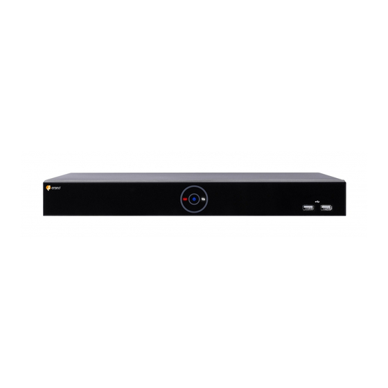
Page 8: Package Contents
Package Contents The device package contents consist of the following: Note Please check all components involved. Table 1-1 Package contents Name Name SATA cable DC Power Adapter & Power cord SATA power cable Mouse HDD fixing screw Quick guide Program CD DVR Description Each part is listed in the below: Figure 1-1 Name and Connection of each front section... - Page 9 4ch DVR 8ch DVR Figure 1-2 Name and Connection of each rear section of 4ch and 8ch DVR Table 1-3 Name and Function of each rear section of 4ch and 8ch DVR Name Function Audio In Camera audio input port. Video In Camera video input port.
-
Page 10: Installation
Installation This chapter describes the way to install DVR. When installing a device, connect rear of the device with each port on the basis of below connection map. Figure 2-1 Connection map The device starts first like below sequences: 1 Installing HDD. 2 Connecting with an exterior device. -
Page 11: Installing Hdd
Installing HDD How to install HDD in the device: Withdraw the mains plug before installing HDD to reduce the risk of injury or electrical shock, or device malfunction. Attention Make sure to check the compatibility of HDD with the device. 1 Always switch off and unplug the unit. - Page 12 6 Connect a monitor with VGA, HDMI or CVBS port. 7 Connect a network port. 8 Connect an alarm and RS485 devices. 9 Connect USB port in front section of the unit with a mouse. 10 Supply the main power after completion. Before connection, match socket with adapter pins.
-
Page 13: Starting System
Starting System Power supply begins with system operation as follows: 1 Switching on initialize with below icons in order. Note Installing new HDD might take more initialize time. 2 With buzzer sounds, the start screen is presented. 3 In Log in screen, enter the ID, Password and press OK. Default ID &... -
Page 14: Quick Setup
Quick Setup First start of the system operates Easy Installation as follows: 1 Account 2 System 3 Network 4 Time/Date 5 Record 2.4.1 Account How to set Account of Easy Installation: 1 Click the keyboard icon to set ID and Password users want. 2 With keyboard UI, set the ID and Password, and press OK. -
Page 15: System
2.4.2 System How to set the system of Easy Installation: 1 Set each item in System setting screen. System Mode: Select input video type(Analog Only or Analog+IP cam) Language: Select system language. Device Name: Enter the device name. ... -
Page 16: Time/Date
2 Press Save button to save set value. 3 Press Next to end Network setting and move the next setting phase. 2.4.4 Time/Date How to set the time/date of Easy Installation: 1 Set each item in Time/Date setting screen. Network Time Sync: Select network for synchronizing with time server. ... -
Page 17: Easy Installation Wizard
Select priority of frame rate or resolution. Select recording modes as continouse or event. Select if audio record or not. Click Calculation to see recommended frame rate and resolution. 2 Press Save button to save set value. 3 Press Next to end Network setting and move the next setting phase. -
Page 18: Live Screen Configuration
Live Screen Configuration UI screen is configured like below figure. Figure 3-1 UI Screen Configuration Table 3-1 Items and Description of UI Screen Configuration Item Description Setting menu is located in the corner of upper screen. See “4 Setup Setup menu menu”... -
Page 19: Icons In Live Screen
Icons in Live screen Each icon in the live screen displays a present setting status or a function. UI screen consists of like below. Chosen live screen is marked as a blue frame; mouse-located live screen is marked Note as yellow one. Figure 3-2 Live screen icon Table 3-2 Live screen icon and its description Icon... -
Page 20: Live Launcher Menu
Live Launcher menu This chapter describes Launcher menu in the bottom of the screen. Figure 3-3 Launcher menu Table 3-3 Launcher menu Item and Description Item Description Log in/out status and logged in ID. Date & Time Displaying present date and time. Displaying HDD capacity in use. -
Page 21: Backup
3.2.1 Backup The device provides a back-up function of live screen. Figure 3-4 Backup Table 3-4 Backup Item and Description Item Description Select CH Selecting a channel users want to back-up. Select All/ Select or clear all channels. Unselect All Start Setting back-up start time (Bookmark: bookmark list). - Page 22 Select Backup Mask and click SET button to open the Privacy Mask pop-up window. Figure 3-5 Backup Mask Table 3-5 Backup Mask Item and Description Item Description Select CH Select the channel to set the privacy zone. Privacy Mask Select whether to use the Privacy Mask. Enable Mask Zone Apply all or only the selected mask.
-
Page 23: Quick Menu
Quick menu This chapter depicts Quick menu when users click the right button of the mouse in live screen. Figure 3-6 Quick menu Table 3-6 Quick menu Item and Description Item Description Screen Mode Selecting the partition mode of live screen (Full, 2X2 and 3X3). Zoom in Magnifying selected live screen (Zoom out, 2 times, 4 times, and 8 times). -
Page 24: Ptz Control
3.3.1 PTZ Control The location of images may be moved to monitor with PTZ ball. PTZ Control menu can be displayed if relevant channel’s protocol is set in DEVICE > Note PTZ in the upper live screen. Figure 3-7 Quick menu > PTZ Control Table 3-7 Quick menu >... -
Page 25: Camera Registration
In PTZ Control screen, clicking the right button of the mouse displays Quick menu. Figure 3-8 PTZ Control Quick menu Table 3-8 PTZ Control Item and Description in Quick menu Item Description Preset, Tour, Run PTZ functions. Scan, Pattern Exit Transforming to live screen menu in PTZ Control menu. - Page 26 Table 3-9 Camera Registration Item Description Search the connected IP cameras. Auto Assign Automatically assign the channel windows. Port Show the detected camera port. Assign Selecting the channel windows manually. Model Show detected camera model number. Show detected camera IP address. Status Show connection status.
-
Page 27: Status > System Log
Item Description Mode Select video stream format (RTSP/HTTP). 3.3.3 Status > System log Users can see the system log information in System log tap in Status screen. Figure 3-11 Status > System log in Quick menu Table 3-11 Status of Quick menu > System log Item and Description Item Description Start... -
Page 28: Status > Event
3.3.4 Status > Event Users can see the real-time event information of the unit in Event tap in Status screen. Figure 3-12 Status > Event in Quick menu Table 3-12 Status > Event Item and Description in Quick menu Item Description Temporary fixing or releasing an event list (toggle). -
Page 29: Status > Record
3.3.5 Status > Record Users can see the recording status in Record tap in Status screen. Figure 3-13 Status > Record in Quick menu Table 3-13 Status > Record Item and Description in Quick menu Item Description Record time Marking recorded period. Record list Displaying the record setting status. -
Page 30: Status > Disk
3.3.6 Status > Disk Users can see the disk status in Disk tap in Status screen. Figure 3-14 Status > Disk in Quick menu Table 3-14 Status > Disk Item and Description in Quick menu Item Description Disk Info Display disk temperature and S.M.A.R.T information. Rec. -
Page 31: Setup Menu
Setup menu This chapter describes Setup menu in the upper side of the screen. Figure 4-1 Setup menu Selecting the menu opens the setting screen. Setup screen is available to click Setup in Quick menu by clicking the right button Note of the mouse. - Page 32 Setup menu includes: Table 4-2 Setup menu tree 1 Depth 2 Depth 3 Depth System System F/W Upgrade Time/Date Time/Date Holiday SYSTEM Account User Export/Import Configuration Factory Default Basic Basic Audio In/Out CAMERA Scan Mode Advanced Advanced Display Spot Display Sequence DEVICE Setup...
-
Page 33: General Buttons In Setup Menu
1 Depth 2 Depth 3 Depth Video Loss Setup Periodic Notification Schedule Basic WAN Port DVRNS/Dashboard DVRNS/DDNS DDNS E-Mail E-Mail NETWORK Notification Server Notification Server Notification Message General buttons in Setup menu This section depicts General buttons in Setup menu. Figure 4-2 General buttons in Setup menu Table 4-3 Item and Description of General buttons in Setup menu Item... -
Page 34: System
Item Description Cancel Cancel the set value. Restore Cancel the set value, and reverse it to default. Apply Apply the content set. SYSTEM In SYSTEM, basic system environment is set. 4.2.1 System Set and upgrade the basic items of the system. System >... - Page 35 Name Function System start Select Easy Installation in starting the system. Run Easy Installation. If change video type, system will reboot and all setup go to factory default. Warning System > F/W Upgrade Set the upgraded items of the system. Figure 4-4 SYSTEM >...
-
Page 36: Time/Date
4.2.2 Time/Date Set the date, time, and holidays of the system. Time/Date > Time/Date Set the date, time, and holidays of the system. Figure 4-5 SYSTEM > Time/Date > Time/Date Table 4-6 SYSTEM > Time/Date > Time/Date Item and Description Name Function System Time... - Page 37 Time/Date > Holiday Set holidays of the system. Figure 4-6 SYSTEM > Time/Date > Holiday Table 4-7 SYSTEM > Time/Date > Holiday Item and Description Name Function Year Select years to set holidays. Delete selected holidays. Add Holiday Add holidays. List Display added holiday lists.
- Page 38 Clicking Add Holiday displays holiday addition screen like below. Figure 4-7 SYSTEM > Time/Date > Holiday > Add Holiday Table 4-8 SYSTEM > Time/Date > Holiday > Add Holiday Item and Description Name Function Name Enter the holiday name. Date Display chosen date.
-
Page 39: Account > User
4.2.3 Account > User Set the user’s account of the system. Figure 4-8 SYSTEM > Account > User Table 4-9 SYSTEM > Account > User Item and Description Name Function Add Group Add users’ group. Add User Add users. Group List Display a total group list. - Page 40 Press Add Group button, then Add Group screen displays. Figure 4-9 SYSTEM > Account > User > Add Group Table 4-10 SYSTEM > Account > User > Add Group Item and Description Name Function Name Enter the group name. PERMISSION Select items to permit access.
-
Page 41: Configuration (Config)
4.2.4 Configuration (Config) Set Export/Import and Factory Default of the system. Config > Export/Import Through a save medium, users may apply information set to other devices identically. Figure 4-11 SYSTEM > Config > Export/Import Table 4-12 SYSTEM > Config > Export/Import Item and Description Name Function Device... - Page 42 Config > Factory Default Default the setting value of the device. Figure 4-12 SYSTEM > Config > Factory Default Table 4-13 SYSTEM > Config > Factory Default Item and Description Name Function Select All Select/deselect all items to be defaulted. /Unselect All Default Item Select/deselect related items to be defaulted.
-
Page 43: Camera
CAMERA In CAMERA section, set the camera to be connected with the device. 4.3.1 Basic Set the fundamental functions of camera and audio. Basic > Basic Set the basic items of camera by channels. Figure 4-13 CAMERA > Basic > Basic Table 4-14 CAMERA >... - Page 44 Press Copy Covert Setup button, then Copy Covert Setup screen displays. Figure 4-14 CAMERA > Basic > Basic > Copy Covert Setup Table 4-15 CAMERA > Basic > Basic > Copy Covert Setup Item and Description Name Function From Select a channel converted setting. Select a channel to be copied.
- Page 45 Basic > Audio In/Out How to set audio of camera across channels Figure 4-15 CAMERA >Basic > Audio In/Out Table 4-16 CAMERA > Basic > Audio In/Out Item and Description Name Function Display channels of audio Select/deselect whether to use audio. Assign Select channels to be assigned audio.
-
Page 46: Advanced
4.3.2 Advanced Set camera video, stream and privacy mask. Advanced > Scan Mode Figure 4-16 CAMERA > Advanced > Scan Mode Table 4-17 CAMERA > Advanced > Scan Mode Item and Description Name Function Display channels. Scan Mode Automatically detects the camera input type or fixes the input video format to the selected type (Auto, AHD, TVI). - Page 47 Advanced > Analog Camera Figure 4-17 CAMERA > Advanced > Analog Camera Table 4-18 CAMERA > Advanced > Analog Camera Item and Description Name Function Display channels. Video Set brightness, contrast, and color of the camera. Privacy Mask Set the privacy field; display field numbers set in parenthesis (at most 4 setting available).
- Page 48 Locate the mouse in the Privacy Mask field, and then click Editing Icon ( ) in the right corner, then Privacy Mask screen displays. Figure 4-18 CAMERA > Advanced > Privacy Mask Table 4-19 CAMERA > Advanced > Privacy Mask Item and Description Name Function Select channels to set privacy field.
- Page 49 Advanced > IP Camera Figure 4-19 CAMERA > Advanced > IP Camera Table 4-20 CAMERA > Advanced > IP Camera Item and Description Name Function Camera Opens a pop-up menu for IP camera registration. Registration Display channels. Video Set brightness, contrast, and color of the camera. Stream Setup camera stream such as Resolution, Framerate, Bitrate and etc.
-
Page 50: Device
DEVICE In DEVICE, set the device to connect with the unit. 4.4.1 Display Set matters related to a display device and live screen. Display > Display Set the display device. Figure 4-20 DEVICE > Display > Display Table 4-21 DEVICE > Display > Display Item and Description Name Function HDMI/VGA... - Page 51 Display > Spot Set the output of the Spot monitor. Figure 4-21 DEVICE > Display > Spot Table 4-22 DEVICE > Display > Spot Item and Description Name Function Sequence Set the channel and dwell time (5, 10, 20, 30sec) when the Auto mode of Spot Monitor is selected.
- Page 52 Display > OSD Set the OSD of the display device. Figure 4-22 DEVICE > Display > OSD Table 4-23 DEVICE > Display > OSD Item and Description Name Function Camera Name Select the way to display camera in live screen (Off, CH+Title, CH). Live Bar Select the way to display the live bar (Always On, Auto Hide).
- Page 53 Display > Sequence How to set the play sequence of live screen Figure 4-23 DEVICE > Display > Sequence Table 4-24 DEVICE > Display > Sequence Item and Description Name Function Quad Sequence Set to convert automatically as 4-partition screen on the time basis. Division Select screen partition mode to be marked in the below table (All, Full, and Quad).
- Page 54 Clicking Add Sequence displays Add Sequence screen. Figure 4-24 DEVICE > Display > Sequence > Add Sequence Table 4-25 DEVICE > Display > Sequence > Add Sequence Item and Description Name Function Dwell Time Select time to play (3 sec, 5 sec, 10 sec, 15 sec, and 30 sec). Division Select the partition screen to play (Full, Quad).
-
Page 55: Disk
4.4.2 Disk Disk > Setup The way to set the disk Figure 4-25 DEVICE > Disk > Setup Table 4-26 DEVICE > Disk > Setup Item and Description Name Function Refresh disk information. Disk Info Display the basic disk information in disc list. ... - Page 56 Name Function Overwrite Select/deselect to rewrite new data on the existing disk in case of Recording insufficient saving space remained. Auto Delete Select/deselect to use the function to delete saved data automatically (1- 365 days). Disk > iSCSI The way to set the iSCSI .
- Page 57 Clicking Register displays iSCSI Register screen. Figure 4-27 DEVICE > Disk > iSCSI > Register Table 4-28 DEVICE > Disk > iSCSI > Register Item and Description Name Function Target Address Input IP address and port for iSCSI. Target Port HTTP Port Discover Click to search iSCSI storage.
-
Page 58: Ptz > Ptz
4.4.3 PTZ > PTZ To use PTZ Function of the device, users need to match ID, protocol, and speed with each camera. Figure 4-28 DEVICE > PTZ > PTZ Table 4-29 DEVICE > PTZ > PTZ Item and Description Name Function Copy PTZ Setup Apply setting history to all or selected channels in the same way. -
Page 59: Serial Device > Serial Device
4.4.4 Serial Device > Serial Device Users need to set Serial Device to connect PTZ camera, USB device with the unit. Figure 4-29 DEVICE > Serial Device > Serial Device Table 4-30 DEVICE > Serial Device > Serial Device Item and Description Name Function USB (to Serial) -
Page 60: Text > Text
4.4.5 TEXT > TEXT Set the input device such as ATM or POS, etc. Figure 4-30 DEVICE > TEXT > TEXT Table 4-31 DEVICE > TEXT > TEXT Item and Description Name Function Select/deselect whether to use text function. Select camera channels to connect with the text input device. Protocol Select protocol to correspond with the text input device. - Page 61 Press Copy to TEXT Setup button, then Copy to TEXT Setup screen displays. Figure 4-31 DEVICE > TEXT > TEXT > Copy to TEXT Setup Table 4-32 DEVICE > TEXT > TEXT > Copy to TEXT Setup Item and Description Name Function From...
-
Page 62: Record
RECORD In RECORD, users may set matters related to recording. 4.5.1 Schedule Schedule > Schedule Recording types can be set across channels and time. Figure 4-32 RECORD > Schedule > Schedule Table 4-33 RECORD > Schedule > Schedule Item and Description Name Function Select channels to set schedules. - Page 63 The function of each scheduling type involves: Table 4-34 Function of each scheduling type Color Scheduling type Function None Do not record. Continuous Record on consecutive mode when time set. Motion Record on event recording mode when motion sensitive event occurs. Alarm Record on event recording mode when alarm occurs.
- Page 64 7 Copy Schedule Setup screen displays. 8 Select channels to be copied. 9 Select channels to apply copied content. 10 Copy the schedule by pressing Apply. 11 Press Save to save the schedule. Schedule > Quick Figure 4-33 RECORD > Schedule > Quick...
- Page 65 Table 4-35 RECORD > Schedule > Quick Item and Description Name Function Desired Recording Select desired recording period. Period Recording Hours per Select recording hours per day. HDD Size It is automatically displayed. Stream Priority Select Framerate or Resolution. Recording mode Select recording mode as Continuous or Event.
-
Page 66: Main Stream
4.5.2 Main Stream To set the image resolution when event occurs across channels or general recording is in process. Main Stream > Analog Camera To set the image quality and resolution of Main Stream Figure 4-34 RECORD > Stream > Main Stream Table 4-36 RECORD >... - Page 67 Clicking Copy Stream Setup opens Copy Stream Setup. Figure 4-35 RECORD > Stream > Main Stream > Copy Stream Setup Table 4-37 RECORD > Stream > Main Stream > Copy Stream Setup Item and Description Name Function From Select the channel set. Select the device to be copied.
- Page 68 Table 4-38 RECORD > Main Stream > IP Camera Item and Description Name Function Display channels. Resolution Show camera main stream setup status. Framerate Bitrate Continuous Select recording stream in case of Continuous mode. Event Select recording stream in case of Event mode. Pre-Alarm Start recording before set time, if event occurs (null, 1 sec, 2 sec, 3 sec, 4 sec, and 5 sec).
-
Page 69: Second Stream
4.5.4 Second Stream Second Stream > Analog Camera To set the image quality and resolution of Second Stream Figure 4-37 RECORD > Stream > Second Stream Table 4-39 RECORD > Stream > Second Stream Item and Description Name Function Display channels. Resolution Set the resolution of video clips (640X480). - Page 70 Second Stream > IP Camera Figure 4-38 RECORD > Second Stream > IP Camera Table 4-40 RECORD > Second Stream > IP Camera Item and Description Name Function Display channels. Resolution Show camera main stream setup status. Framerate Bitrate Pre-Alarm Start recording before set time, if event occurs.
-
Page 71: Panic
4.5.5 Panic How to set immediate recording Figure 4-39 RECORD > Stream > Panic Table 4-41 RECORD > Stream > Panic Item and Description Name Function Panic Record Select/deselect to use immediate recording function. Display channels. Resolution Set the resolution of video clips (4MP, 1080P, 720P, 960H). Frame rate Select recording FPS (1-30). -
Page 72: Event
EVENT In EVENT, users may set each event of the device. 4.6.1 System/Disk To set the system and disk event System/Disk > System To set the system event of the device Figure 4-40 Event > System/Disk > System Table 4-42 Event > System/Disk > System Item and Description Name Function System Restart... - Page 73 System/Disk > Disk To set disk event Figure 4-41 Event > System/Disk > Disk Table 4-43 Event > System/Disk > Disk Item and Description Name Function Disk Unplugged Select/deselect whether to use disk unplugged event. Beep Select/deselect whether to use buzzer sound in case of event. Alarm out Select to end alarm time (null, Relay1-Keep, 5 sec, 10 sec, 20 sec, 30 sec, 1 min, 10 min, 30 min, and 1 hour).
-
Page 74: Alarm In
4.6.2 Alarm In To set sensor alarms and schedule Alarm In > Setup To set sensor alarms Figure 4-42 Event > Alarm In > Setup Table 4-44 Event > Alarm In > Setup Item and Description Name Function Sensor Display sensor numbers. Select/deselect whether to use alarm in the sensor. - Page 75 Placing your mouse on Alarm, Group Rec, Noti., Preset and clicking editing Icon( ) in right corner displays Event : Alarm screen. Figure 4-43 Event > Alarm In > Setup > Event : Alarm Table 4-45 Event > Alarm In > Setup > Event : Alarm Item and Description Name Function Alarm-out...
- Page 76 Alarm In > Schedule To schedule recording time when alarm occurs across device sensors Figure 4-44 Event > Alarm In > Schedule Table 4-46 Event > Alarm In > Schedule Item and Description Name Function Sensor Select the sensor to set the schedule. Schedule Type Select the types of schedules.
-
Page 77: Motion
4.6.3 Motion To set and schedule motions across channels Motion > Setup To set motions across channels. Figure 4-45 Event > Motion > Setup Table 4-47 Event > Motion > Setup Item and Description Name Function Display channels. Select/deselect whether to use motion function in the channel. Area Display the motion area. - Page 78 Event : Motion screen, see section “4.6.2 Alarm In > Setup in Alarm In.” Motion > Schedule To schedule record time when the motion sensor detects across channels Figure 4-46 Event > Motion > Schedule Table 4-48 Event > Motion > Schedule Item and Description Name Function Select channels to set schedules.
-
Page 79: Video Loss
4.6.4 Video Loss To set Video Loss across channels Figure 4-47 Event > Video Loss > Setup Table 4-49 Event > Video Loss > Setup Item and Description Name Function Display channels. Select/deselect whether to use Video Loss in the channel. Beep Select use time of buzzer sound (null, 5 sec, 10 sec, 20 sec, 30 sec, 1 min, 10 min, 30 min, and 1 hour). -
Page 80: Notification
4.6.5 Notification To set and schedule periodical alarms Notification > Periodic To set periodical alarms Figure 4-48 EVENT > Notification > Periodic Table 4-50 EVENT > Notification > Periodic Item and Description Name Function Periodic Select/deselect whether to use periodical alarms. Notification Summary Send the save or event information. - Page 81 Notification > Schedule To schedule remote notification (alarm & motion) Figure 4-49 EVENT > Notification > Schedule Table 4-51 EVENT > Notification > Schedule Item and Description Name Function Schedule Type Select the types of schedules. Selection Schedule Table Display the schedule users set. Drag Field Display the area dragged with a mouse.
-
Page 82: Network
NETWORK In NETWORK, users may set the network environment. 4.7.1 Basic > WAN Port To set the network environment Figure 4-50 NETWORK > Basic > WAN Port Table 4-52 NETWORK > Basic > WAN Port Item and Description Name Function Static IP Check if you use static IP. -
Page 83: Dvrns/Ddns
4.7.2 DVRNS/DDNS To set DVRNS/DDNS DVRNS/DDNS > DVRNS/Dashboard To register DVRNS/Dashboard account Figure 4-51 NETWORK > DVRNS/DDNS > DVRNS/Dashboard Table 4-53 NETWORK > DVRNS/DDNS > DVRNS/Dashboard Item and Description Name Function DVRNS Register DVRNS account. ID: Enter DVRNS ID (default: MAC address of the unit) ... - Page 84 DVRNS/DDNS > DDNS To set DDNS site for remote users to access in networking Figure 4-52 NETWORK > DVRNS/DDNS > DDNS Table 4-54 NETWORK > DVRNS/DDNS > DDNS Item and Description Name Function DDNS Site Select DDNS site. Host Name Enter the host name.
-
Page 85: E-Mail
4.7.3 E-Mail To set email server to send email on the occasion of event Figure 4-53 NETWORK > E-Mail > E-Mail Table 4-54 NETWORK > E-Mail > E-Mail Item and Description Name Function Server Type Select SMTP server. gmail.com ... -
Page 86: Ftp
4.7.4 Set up FTP server to send video to FTP server. The file format is AVI file. Figure 4-55 NETWORK > FTP > FTP Table 4-55 NETWORK > FTP > FTP Name Function FTP Server Select whether to use FTP. Address(URL)/Port Enter server address and port. -
Page 87: P2P
4.7.5 User can connect recorder from mobile app using QR code scan. Figure 4-56 NETWORK > P2P > P2P Table 4-56 NETWORK > P2P > P2P Name Function P2P Registration Click button to check up registration status. P2P QR Code Scan QR code using mobile app to connect recorder. -
Page 88: Notification Server
4.7.6 Notification Server Notification Server > Notification Server Figure 4-57 NETWORK > Notification Server > Notification Server Table 4-57 NETWORK > Notification Server > Notification Server Name Function Notification Server Select/deselect whether to use Notification Server. Type Select TCP or UDP Protocol. Enter the server IP address or host name. - Page 89 Notification Server > Notification Message Set up the message to be sent to the notification server when event occurs. Figure 4-58 NETWORK > Notification Server > Notification Message Table 4-58 NETWORK > Notification Server > Notification Message Name Function Deleted registered notification message. Notification message edit window pop-up.
- Page 90 Table 4-59 NETWORK > Notification Server > Notification Message > Add Message Name Function Select the channel to add a message. Event Select the event type (motion, alarm, video loss). Message Create a message to send.
-
Page 91: Search/Playback
Search/Playback This chapter describes Live Launcher search and play menu in the below screen bar. Figure 5-1 Live Launcher Search, Play menu Table 5-1 Item and Description of Live Launcher Search, Play menu Item Description Search recorded data (time, event, thumbnail, smart search and text). Playback recorded data. - Page 92 Search > Event Recording data is searched by event type. Figure 5-3 Search: Event Table 5-3 Search: Event Item and Description Item Description Select CH Select channels to search. Select All Select/deselect all channels. /Unselect All Start Setting starting time to search. Setting ending time to search.
- Page 93 Item Description Time Selecting time to search. Interval Setting time interval for searching images. Time Playing or stopping videos searched. Lapse/Pause Cancel Ending search screen. Search > Smart Search Recording data is searched by detecting change of specific area. Figure 5-5 Search: Smart Search Table 5-5 Search: Smart Search Item and Description Item Description...
- Page 94 Table 5-6 Search: TEXT Item and Description Item Description Select CH Select channels to search. Select All Select/deselect all channels. /Unselect All Start Setting starting time to search. Setting ending time to search. Keyword Entering keyword to search. Case Sensitive Searching items in case-sensitive.
-
Page 95: Playback
Playback To play recorded data Figure 5-7 Playback Launcher Table 5-7 Playback Launcher Item and Description Item Description Displaying present play status. Date and Time Displaying date and time of playing videos. Moving to the first section of the video. Playing the videos with multiplied speed in reverse (2~64x). - Page 96 Table 5-8 Playback Launcher > Record Time-Line Item and Description Name Function Shows the recording status. Select the desired time with the mouse to Time lines playback. Add bookmarks at the selected time in the Time line. Run a Manual backup. See “3.2.1 Backup” to display detailed information about back-up.
-
Page 97: Webviewer
Webviewer This chapter describes webviewer for monitoring videos through a PC in remote mode. How to monitor with webviewer. Table 6-1 System Requirement for Webviewer Item Recommended Minimum MicrosoftⓇ WindowsⓇ 10 x86(64bit) MicrosoftⓇ WindowsⓇ XP Home SP3 (Home Premium, Professional, Ultimate) MicrosoftⓇ... - Page 98 In case of selecting Viewer(Internet Explorer) Click Viewer. When Java download screen opens, download and install JAVA. Live images may be monitored.
- Page 99 In case of selecting Viewer(Chrome) After click Viewer, .jnlp file can be downloaded. Click Keep button. Click webviewer_chrome.jnlp. When Java download screen opens, download and install JAVA. Live images may be monitored.
- Page 100 In case of selecting Setup Users can set the menu in similar ways with NVR connected monitor. Figure 6-1 Setup screen...
- Page 101 Products Specifications Channel Video Input Channel Up to 4ch (4 BNC, 1 IP configurable) Up to 8ch (8 BNC, 2 IP configurable) Video Input Type AHD, TVI, CVBS, IP AHD, TVI, CVBS, IP Video 4M, 1080p, 720p, 960H, D1(CVBS) 4M, 1080p, 720p, 960H, D1(CVBS) Input Up to 3M Up to 3M...
- Page 102 Ethernet 1 RJ45 1 RJ45 10/100/1000 Base-T 10/100/1000 Base-T Max. Network Unlimited Unlimited Throughput (Guarantee 72Mbps, Support Bandwidth (Guarantee 144Mbps, Support Bandwidth Control) Control) Remote Monitoring CMS, Mobile, Web, Dashboard CMS, Mobile, Web, Dashboard Audio 4 RCA Input 4 RCA Input 1 RCA, 1HDMI Output 1 RCA, 1HDMI Output Alarm...
- Page 103 Appendix: GDPR functions Recorders of the series: IER, MSR...
- Page 104 GDPR features of IER and MSR series recorders Four-eye principle In order to access or export video data, two users must log on to the device with their credentials one after the other. This may be one employee and the company’s data protection officer, for example (according to Art. 32 GDPR). Defined storage times per video channel.
- Page 105 Differentiated authorisation management Different user groups with different authorizations can be created in the configuration menu. Camera selection for each user. Individual group configuration. Maintenance user without video access (e.g. for installers) (according to Art. 32 GDPR). Detailed log informations Users with the required authorisation can access detailed log-in records to find out with absolute certainty who exported video data, when they did so and whether they complied with the company’s privacy policy (according to Art.
- Page 106 Password change cycle & automatic logout during inactivity • If someone forgets to log out ... • ... so that passwords are changed regularly! (according to Art. 32 GDPR) Cameras on the PoE port can be isolated (NAT/IPC) Normally, the cameras can be reached on the PoE port in the network, but this can be completely isolated (according to Art. 32 GDPR).
- Page 107 VIDEOR E. Hartig GmbH Exclusive distribution through special- ised trade channels only. VIDEOR E. Hartig GmbH Carl-Zeiss-Straße 8 63322 Rödermark/Germany Tel. +49 (0) 6074 / 888-0 Technical changes reserved Fax +49 (0) 6074 / 888-100 www.videor.com...
Need help?
Do you have a question about the MSR-24N040004A and is the answer not in the manual?
Questions and answers