
Related Manuals for TeeJet Technologies MATRIX PRO GS


Summary of Contents for TeeJet Technologies MATRIX PRO GS
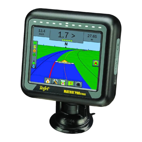
- Page 1 MATRIX PRO GS ® VOYAGER 570G U S E R M A N U A L U S E R M A N U A L Software version 4.21...
- Page 2 GETTING STARTED #1 Turn Power On Press the POWER button to power on the console. #2 Home Screen Once the power up sequence has completed, the Home screen will appear with the option to start a new job or continue an existing job. #3 Go to Unit Setup 1.
-
Page 3: Table Of Contents
Matrix® Pro 570GS ● Matrix® Pro 840GS Table of Contents CHAPTER 1 – INTRODUCTION Product Upgrades Available ..................................1 SYSTEM COMPONENTS Matrix Pro 570GS Console ...................................1 Matrix Pro 840GS Console ...................................2 Buttons ..........................................2 Additional Information ....................................2 RealView® Camera ......................................3 CONFIGURATIONS BASIC SCREEN USE Bottom Tab Keys ...............................3 Unavailable Options When Job is Active ........................3 Console Screen Colors..............................4... - Page 4 Matrix® Pro 570GS ● Matrix® Pro 840GS CONFIGURATION Implement ........................................13 Implement Type ................................13 Single Section Setup ..............................13 Multiple Sections with SDM/SFM Setup ........................14 Droplet Size Monitor ..............................15 Tip Selection ................................16 Reverse Sense Module ............................16 Guidance [Lightbar] ....................................17 AutoSteer ........................................18 Assisted/Auto Steering Unavailable ..........................18 FieldPilot [using a SCM] ............................18 FieldPilot Pro / UniPilot Pro [using a SCM Pro] ......................18...
- Page 5 Matrix® Pro 570GS ● Matrix® Pro 840GS CHAPTER 5 – GNSS RECEIVER CONFIGURATION GNSS Receiver Configuration .................................. 34 GNSS Type ................................35 GNSS Port ................................35 External Receiver Minimum Configuration Requirements .....................35 GNSS Status Information ............................36 GNSS Status Information on Guidance Screens ......................36 GGA Requirements ................................36 Program ..................................37 PRN ..................................37...
- Page 6 Matrix® Pro 570GS ● Matrix® Pro 840GS Operation ........................................53 Status Bar ................................53 Droplet Size Chart................................53 Guidance Bar ................................53 BOOMPILOT BoomPilot Start Mode .............................54 BoomPilot Icon ................................55 CHAPTER 7 – GUIDANCE Navigation Screens Options ..................................57 GUIDANCE BAR Navigation Activity & Boom Status ...........................58 Cross Track Error ................................58 Selectable Information.............................59 STATUS BAR...
- Page 7 Matrix® Pro 570GS ● Matrix® Pro 840GS BOOMPILOT No Section Control Module ..................................74 Console Only ................................74 With Optional Work On/Off Switch ...........................74 Using the Console................................74 With TeeJet Section Control Module and Switchbox or ISM ......................75 With TeeJet Section Control Module ..............................75 ZOOM IN/OUT Vehicle View ........................................
- Page 8 Matrix® Pro 570GS ● Matrix® Pro 840GS APPENDIX A – SYSTEM CONFIGURATIONS APPENDIX B – MATRIX PRO GS CONSOLE MENU SETTINGS APPENDIX C – UNIT SPECIFICATIONS APPENDIX D – SETTING RANGES APPENDIX E – UTM COORDINATES AND ZONES www.teejet.com...
-
Page 9: Chapter 1 - Introduction
Matrix® Pro 570GS ● Matrix® Pro 840GS CHAPTER 1 – INTRODUCTION The Matrix Pro GS allows the management of multiple connected modules plus GNSS mapping, Guidance, FieldPilot ® , BoomPilot ® , Rate Control, and data collection in a single console using CAN bus technology. This replaces multiple consoles in the cab with one robust system. -
Page 10: Matrix Pro 840Gs Console
On – Press the POWER button to power on the console. Upon attaching equipment to the Matrix Pro GS system. power up, the Matrix Pro GS will begin its start up sequence. Off – Press and briefly hold the POWER button until a Start Up Sequence confirmation screen acknowledges shut down mode. -
Page 11: Realview® Camera
BASIC SCREEN USE The Matrix Pro GS can be used as a simple current job system or advanced multi-job system. Regardless of which mode the console is in, the basic screen functions are the same. • Bottom Tabs and Side Tabs access the various screens and sub-screens •... -
Page 12: Console Screen Colors
Matrix® Pro 570GS ● Matrix® Pro 840GS Console Screen Colors Simple or Advanced Mode The console is available in six color schemes. From the System To change between simple mode and advanced mode, see the configuration chapter under Data –> Options. Setup Bottom Key, press CONSOLE side tab and enter options. -
Page 13: Warnings And Information Pop-Ups
Matrix® Pro 570GS ● Matrix® Pro 840GS Warnings and Information Pop-ups Drop Down Menu Selections Press DOWN arrow to access the options. Use the UP/DOWN A pop-up warning or information box will be displayed for approximately five (5) seconds. To remove the information box, tap arrows or slide bar if necessary to scroll through the extended anywhere on the screen. -
Page 14: Keyboard Entry Screen
Matrix® Pro 570GS ● Matrix® Pro 840GS Keyboard Entry Screen Next Page Press the KEYPAD icon . Use the numeric keypad to enter Press the NEXT PAGE arrow to set up additional options for the a value. selected item. Figure 1-13: Example of Next Page Press the ACCEPT icon to save the settings or the CANCEL icon... -
Page 15: Chapter 2 - Jobs / Home Screen
See Client information, farm information, field information, and “Matrix Pro GS Console Menu Settings” in the appendix of this manual. prescription maps can only be inputted using Fieldware Link. A job name can only be edited using Fieldware Link. -
Page 16: Simple Mode
Start Job If a selected job is in a UTM zone other than the current or adjacent The Matrix Pro GS is programmed with a field finder tool to assist UTM zone, will be disabled. the user in finding the job closest to the vehicle’s location. With GPS Continue acquired, the job pick list will be updated every ten seconds. -
Page 17: Chapter 3 - Full Screen Video View
Matrix® Pro 570GS ● Matrix® Pro 840GS CHAPTER 3 – FULL SCREEN VIDEO VIEW RealView Full Screen Video View allows live video input to be displayed. View video feed(s) and setup cameras without GNSS available. Options for RealView Guidance are not available on this screen. ►Single Camera –... -
Page 18: Camera Snapshot
Matrix® Pro 570GS ● Matrix® Pro 840GS Figure 3-3: Single Camera Selection with VSM Camera Snapshot RealView Camera Snapshot saves a still photo of the current view on the screen to a USB drive. 1. Insert USB drive. 2. Press REALVIEW CAMERA FULL SCREEN VIDEO VIEW bottom tab 3. -
Page 19: Chapter 4 - System Setup
Matrix® Pro 570GS ● Matrix® Pro 840GS CHAPTER 4 – SYSTEM SETUP System Setup is used to configure the console, the machine and its implements. Four side tabs access options for Machine/Implement Configuration, Data Management, Console Settings, and Tools. OVERVIEW Data Management Four side tabs access setup options for: Implement Configuration... -
Page 20: Configuration
CONFIGURATION Configuration is used to configure the Implement, Guidance, GNSS Receiver, Video, Sensors, AutoSteer, and Tilt Correction. NOTE: Feature availability will vary depending on the devices available on the Matrix Pro GS system. 1. Press SYSTEM SETUP bottom tab 2. Press CONFIGURATION side tab 3. -
Page 21: Implement
Matrix® Pro 570GS ● Matrix® Pro 840GS Figure 4-4: Implement Type – Spreader Implement Implement Setup is used to establish the various settings associated with straight mode, spreader mode, or staggered mode. Available settings will vary depending on the specific equipment present in the system. -
Page 22: Multiple Sections With Sdm/Sfm Setup
Matrix® Pro 570GS ● Matrix® Pro 840GS ►Tip Selection [when available] – used to select the type of Multiple Sections with SDM/SFM Setup sprayer tip (series and capacity) for determining droplet size Multiple Sections with SDM/SFM Setup is used when a Section Driver Module (SDM) or Switch Function Module (SFM) is on the information ►Applied Alert –... -
Page 23: Droplet Size Monitor
Matrix® Pro 570GS ● Matrix® Pro 840GS Figure 4-7: Implement – Multiple Sections with SDM or SFM Setup Droplet Size Monitor When the system includes a Pressure Sensor Interface Kit (PSIK), or a Dual Control Module with Product Control Application Type set to "Liquid"... -
Page 24: Tip Selection
Matrix® Pro 570GS ● Matrix® Pro 840GS Tip Selection Reverse Sense Module Tip Selection enables up to five (5) tips to be preset for quick recall, Reverse Sense Module Setup is used when adding a Reverse and the current tip to be selected. Sense Module or SCM Pro (Steering Control Module Pro) to any configuration. -
Page 25: Guidance [Lightbar]
Matrix® Pro 570GS ● Matrix® Pro 840GS Figure 4-11: Guidance with External Lightbar Module (ELM), Guidance [Lightbar] Guidance options are used to configure the Cross Track Error shown on the on the lightbar. NOTE: In previous software versions, this feature was referred to as "Lightbar".\ An optional External Lightbar Module (ELM) may be used to provide additional guideance information. -
Page 26: Autosteer
Matrix® Pro 570GS ● Matrix® Pro 840GS ►Steering Angle Sensor – used to establish and calibrate the AutoSteer Steering Angle Sensor (SAS) as the primary feedback sensor When a Steering Control Module (SCM or SCM Pro) is present, for auto steering Assisted/Auto Steering options will be available. -
Page 27: Active Vehicle
FieldPilot Pro or UniPilot Pro. This is a critical safety feature that should only be disabled when instructed by the machine manufacturer or TeeJet Technologies. 4. Press RETURN arrow or CONFIGURATION side tab return to the main Configuration screen. -
Page 28: Tilt Correction
Matrix® Pro 570GS ● Matrix® Pro 840GS Tilt Correction GNSS Receiver Configuration GNSS Receiver Configuration is used to configure GNSS Type, When a Steering Control Module (SCM) or Tilt Gyro Module (TGM) is present, Tilt Correction is available. This corrects the GNSS signal GNSS Port, and PRN, as well as to view GNSS status information. -
Page 29: Video
Matrix® Pro 570GS ● Matrix® Pro 840GS Video Sensors When a Pressure Sensor Interface Kit (specifically, an Input Output Video Setup is used to set up a single directly connected camera Module (IOM)) is on the system, options to set up and configure the or individual cameras while using an Eight (8) Channel or Four (4) Channel Video Selector Module (VSM). -
Page 30: Sensors Unavailable
Matrix® Pro 570GS ● Matrix® Pro 840GS Sensors Unavailable Droplet Size Monitor If a Pressure Sensor Interface Kit is being used, the Droplet Size If a Pressure Sensor Interface Kit is not installed, setup options will not be available. Monitor options will be available. 1. -
Page 31: Data Management
Matrix® Pro 570GS ● Matrix® Pro 840GS DATA MANAGEMENT Data Management allows for transfer and management of job 1. Press DATA MANAGEMENT side tab data, reporting of job data, changing of job mode, and transfer and 2. Press Job Data management of machine settings. -
Page 32: Transfer
Matrix® Pro 570GS ● Matrix® Pro 840GS Transfer Manage When in advanced job mode, the job data transfer screen When in advanced job mode, the job data manage screen allows the allows the transfer of selected jobs to or from a USB drive, as creation of a new empty job, copying of a selected job's Guidelines, Boundaries, Applied Data, and/or Prescription Map to a new job, as well as deleting jobs. -
Page 33: Reports
Matrix® Pro 570GS ● Matrix® Pro 840GS Figure 4-28: Reports – Simple Job Mode Reports Reports is used to create job reports and save them to a USB drive. NOTE: If Simple Job Mode is selected in the Options page, only the current job can be saved. -
Page 34: Machine Settings
• Job-specific settings (including application rates, application type, and Product Channel assignments) NOTE: Not all settings are saved as part of the machine settings. See the appendix "Matrix Pro GS Console Menu Settings" for details. 1. Press DATA MANAGEMENT side tab Machine Settings 2. -
Page 35: Transfer
NOTE: Not all settings are saved as part of the machine settings. See the appendix "Matrix Pro GS Console Menu Settings" NOTE: Not all settings saved as part of the machine settings are for details. -
Page 36: Console
Matrix® Pro 570GS ● Matrix® Pro 840GS CONSOLE Console Setup is used to configure the display and cultural settings, About About/Save screen displays the system software version as well as unlock advanced features, connect to wireless network, and play the software versions of modules connected to the CAN bus. back demo GNSS data. -
Page 37: Display
Matrix® Pro 570GS ● Matrix® Pro 840GS Display Cultural Display is used to configure color scheme and LCD brightness, Cultural is used to configure units, language, and time zone settings. establish screenshot availability and calibrate the touchscreen. 1. Press CONSOLE side tab 1. -
Page 38: Audio Volume
Matrix® Pro 570GS ● Matrix® Pro 840GS Audio Volume Demo GNSS Demo GNSS is used to start the playback of a simulated GNSS Audio Volume adjusts the volume level of the audio speaker. signal. 1. Press CONSOLE side tab WARNING! This tool will disable incoming GNSS positions and begin Audio Volume 2. -
Page 39: Restart Demo Gnss
Matrix® Pro 570GS ● Matrix® Pro 840GS Restart Demo GNSS Figure 4-40: Feature Unlocked Demonstration GNSS can be restarted. 1. Press CONSOLE side tab 2. Press Demo GNSS 3. Press Restart 4. Press RETURN arrow or CONSOLE side tab to return to the main Console Settings screen. -
Page 40: Tools
Matrix® Pro 570GS ● Matrix® Pro 840GS TOOLS Figure 4-42: Upload Software Tools is used to upload software updates for system devices, and to do various calculations on a regular calculator or a unit converter. 1. Press SYSTEM SETUP bottom tab 2. -
Page 41: Extras
Matrix® Pro 570GS ● Matrix® Pro 840GS Figure 4-44: Units Converter Extras 1. Press TOOLS side tab 2. Press Extras 3. Select from: ►Calculator – used to perform mathematical calculations ►Units Converter – used to perform unit conversions for area, length, volume, pressure, mass, temperature, or angle Figure 4-43: Calculator Backspace... -
Page 42: Chapter 5 - Gnss Receiver Configuration
Matrix® Pro 570GS ● Matrix® Pro 840GS CHAPTER 5 – GNSS RECEIVER CONFIGURATION GNSS Receiver Configuration is used to configure GNSS Type, GNSS Port, and PRN, and other GNSS parameters, and to view GNSS status information. GNSS Receiver Configuration NOTE: These settings are required for rate control, assisted/ Figure 5-1: GNSS Options auto steering, and tilt sensor operation, as well as proper implement operation. -
Page 43: Gnss Type
Figure 5-2: GNSS Type External Receiver Minimum Configuration Requirements Before the Matrix Pro GS will connect and work with an external GNSS receiver, these minimum configuration requirements must be met. Serial Port Settings Baud rate:... -
Page 44: Gnss Status Information
Matrix® Pro 570GS ● Matrix® Pro 840GS GNSS Status Information GNSS Status Information on Guidance Screens GNSS Status Information displays a snapshot of the current GNSS GNSS Status displays information regarding current GNSS status, including data rates, number of satellites in view, HDOP and PRN status information. -
Page 45: Program
Matrix® Pro 570GS ● Matrix® Pro 840GS Program Alternate PRN Program allows direct programming of the GNSS receiver through a When PRN is not automatic, a second alternate SBAS PRN will command line interface. Only TeeJet support technicians should use provide a second set of GNSS differential correction data. -
Page 46: Gnss Glossary
Matrix® Pro 570GS ● Matrix® Pro 840GS NTRIP (Networked Transportation of RTCM via GNSS Glossary Internet Protocol): Commercial Satellite Provider: An internet-based application that makes the RTCM correction Another common source for DGPS signals. Error correction data from the CORS stations available to anyone with an internet information obtained from their base stations is sent to a connection and the appropriate log-on credentials to the NTRIP communications satellite (separate from the GPS satellites) and... -
Page 47: Chapter 6 - Implement Setup
Matrix® Pro 570GS ● Matrix® Pro 840GS CHAPTER 6 – IMPLEMENT SETUP Implement Setup is used to establish the various settings associated with straight mode, spreader mode, and staggered mode. Settings will vary depending on if there is section control available: SmartCable, Section Driver Module (SDM), or Switch Function Module (SFM). -
Page 48: Straight
Matrix® Pro 570GS ● Matrix® Pro 840GS Figure 6-5: Offset Directions and Distances Straight The boom sections have no length and are on a line a fixed distance from the antenna. Single Section No section control is available on the system. Straight 1. -
Page 49: Spreader - Teejet
Matrix® Pro 570GS ● Matrix® Pro 840GS Figure 6-6: Multiple Sections Figure 6-8: Overlap 100% Spreader – TeeJet A virtual line is created in line with the delivery disks from which Figure 6-7: Offset Directions and Distances the application section or sections can vary in length and can be at different distances from the line (availability depends on the specific equipment in the system). -
Page 50: Multiple Sections
Matrix® Pro 570GS ● Matrix® Pro 840GS Multiple Sections 4. Press RETURN arrow to return to the Implement screen Section control is available (SmartCable, Section Driver Module or CONFIGURATION side tab to return to the main (SDM), or Switch Function Module (SFM) or ISOBUS). Configuration screen. - Page 51 Matrix® Pro 570GS ● Matrix® Pro 840GS Figure 6-12: Multiple Sections Figure 6-14: Lateral Offset Direction and Distance Figure 6-15: Overlap Figure 6-13: Distances and Length 100% 98-05273-ENUS R6...
-
Page 52: Spreader - Oem
Matrix® Pro 570GS ● Matrix® Pro 840GS Multiple Sections Spreader – OEM Section control is available (SmartCable, Section Driver Module A virtual line is created in line with the delivery disks from which (SDM), or Switch Function Module (SFM) or ISOBUS). the application section or sections can vary in length and can be at different distances from the line. -
Page 53: Staggered
Matrix® Pro 570GS ● Matrix® Pro 840GS Figure 6-17: Multiple Sections Staggered A virtual line is created in line with Section 1 from which the application section or sections have no length and can be at different distances from the antenna. Multiple Sections Section control is available (SmartCable, Section Driver Module (SDM), or Switch Function Module (SFM) or ISOBUS). - Page 54 Matrix® Pro 570GS ● Matrix® Pro 840GS Figure 6-18: Multiple Sections Figure 6-20: Offset Directions and Distances – in front of section 1 Figure 6-21: Overlap 100% Figure 6-19: Offset Directions and Distances – behind section 1 www.teejet.com...
-
Page 55: Application Or Working Width
Matrix® Pro 570GS ● Matrix® Pro 840GS APPLICATION OR WORKING WIDTH Application Width [Straight Implement Type or Staggered Implement Type] or Working Width [Spreader Implement Type] is used to enter the width of the single section or width of each section to calculate the total width of the implement. Single Section Multiple Sections Section control is available (SmartCable, Section Driver Module... -
Page 56: Lateral Implement Offset Distance Adjustment
Matrix® Pro 570GS ● Matrix® Pro 840GS LATERAL IMPLEMENT OFFSET DISTANCE ADJUSTMENT Figure 6-24: Lateral Implement Offset Distance Lateral implement offset distance is used to enter the distance from the center line of the machine to the center of the implement. When on-screen mapping shows no overlap or gap, yet field application produces an overlap or gap consistently to only one side in the direction of travel, an adjustment to the lateral implement offset... -
Page 57: Lateral Implement Offset Adjustment
Matrix® Pro 570GS ● Matrix® Pro 840GS Lateral Implement Offset Adjustment To calculate an implement offset adjustment using adjacent guidelines: 1. Create a straight AB line. as if you were operating the implement, and place flags at the outside edges of the 2. -
Page 58: Reverse Sense Module
Matrix® Pro 570GS ● Matrix® Pro 840GS REVERSE SENSE MODULE Reverse on Guidance Screens Reverse Sense Module Setup is used when adding a Reverse Sense Module to any configuration. This allows for application While traveling in reverse, having BoomPilot in Reverse active mapping and control, and on-screen guidance when traveling in will allow for automatic section control. -
Page 59: Tip Selection
Matrix® Pro 570GS ● Matrix® Pro 840GS TIP SELECTION Preset When the system includes a Pressure Sensor Interface Kit (PSIK), Tip presets allow saving of up to five tips for quick recall. Tip Selection is used to select the type of sprayer tip (series and capacity) for determining droplet size information. -
Page 60: Current Tip
Matrix® Pro 570GS ● Matrix® Pro 840GS Current Tip DROPLET SIZE MONITOR Current Tip shows the active tip for determining current droplet size information. Tips must be preset to be available for current tip When the system includes a Pressure Sensor Interface Kit (PSIK), Droplet Size Monitor can be enabled/disabled. -
Page 61: Tip Selection / Current Tip
Matrix® Pro 570GS ● Matrix® Pro 840GS Tip Selection / Current Tip Droplet Size Chart When choosing a spray tip that produces droplet sizes in one of the To establish the tip presets and current tip, see "Tip Selection" in this eight droplet size classification categories, always remember that a chapter. -
Page 62: Boompilot
Matrix® Pro 570GS ● Matrix® Pro 840GS BOOMPILOT Depending on if there is a section control system present and when BoomPilot Start Mode BoomPilot Start Mode is used to set if the BoomPilot control is present what kind of section control is being used as well as what options are enabled, there are multiple options for BoomPilot section started automatically by speed, or manually by the BoomPilot icon. -
Page 63: Boompilot Icon
Matrix® Pro 570GS ● Matrix® Pro 840GS BoomPilot Icon The BoomPilot Icon is used to activate an icon in the Navigation and Guidance options on the guidance screens for manually controlling BoomPilot 1. Press CONFIGURATION side tab 2. Press Implement 3. -
Page 64: Chapter 7 - Guidance
Matrix® Pro 570GS ● Matrix® Pro 840GS CHAPTER 7 – GUIDANCE The Matrix Pro GS allows product application and vehicle guidance to be performed simultaneously. Once unit setup is complete, guidance can begin. Five guidance modes allow the operator to optimize the field work: Straight AB... -
Page 65: Navigation Screens Options
Matrix® Pro 570GS ● Matrix® Pro 840GS Navigation Screens Options Navigation and Guidance Options Guidance Mode Return to Point Guidance Mode – access to guidance mode Mark Point – establishes a point at options the vehicle location. Grayed = GNSS is unavailable. -
Page 66: Guidance Bar
Matrix® Pro 570GS ● Matrix® Pro 840GS GUIDANCE BAR Screen Options Zoom in/out The Guidance bar keeps you informed of your choice of selectable Icons – to be used on the Matrix Pro 570GS information, navigation activity, and section status. Buttons –... -
Page 67: Selectable Information
Matrix® Pro 570GS ● Matrix® Pro 840GS Selectable Information STATUS BAR Speed – displays the current speed of travel The Status Bar provides information on GNSS status, guidance Heading – displays the course of travel based clockwise from mode, boundary area, assisted/auto steering engagement, tilt a north-south baseline. -
Page 68: Status/Information Screens
Matrix® Pro 570GS ● Matrix® Pro 840GS Status/Information Screens Assisted/Auto Steering Status Green = engaged, actively steering GNSS Status Yellow = enabled, all conditions have been met to allow for GNSS Status displays information regarding current GNSS status, including data rates, number of satellites in view, HDOP and PRN assisted/auto steering status, receiver and version, satellite quality and ID, and UTM zone. - Page 69 Matrix® Pro 570GS ● Matrix® Pro 840GS Bounded Area Status BoomPilot Status Bounded Area Status displays information regarding the areas in the BoomPilot Status displays information regarding the current status of current boundaries. the BoomPilot system. 1. Press BOUNDED AREA icon 1.
-
Page 70: Navigation Screens
Matrix® Pro 570GS ● Matrix® Pro 840GS NAVIGATION SCREENS Guidance and navigation can be accessed from the Vehicle View screen, Field View screen, or RealView screen. • Press NAVIGATION AND GUIDANCE OPTIONS tab to display navigation options. • Press REALVIEW OPTIONS tab to display camera setup and guidance options. -
Page 71: Vehicle View
Matrix® Pro 570GS ● Matrix® Pro 840GS Vehicle View Vehicle View creates a computer-generated image of the vehicle position displayed in the application area. From this screen all setup and navigation options can be accessed via the Options tabs on the right side of the screen. To access the Vehicle View screen: 1. -
Page 72: Field View
Matrix® Pro 570GS ● Matrix® Pro 840GS Field View Field View creates a computer-generated image of the vehicle position and application area from an aerial perspective. From this screen, all setup and navigation options, as well as Pan Mode, can be accessed via the Option tabs on the right side of the screen. To access the Field View screen: 1. -
Page 73: Realview Guidance
Matrix® Pro 570GS ● Matrix® Pro 840GS RealView Guidance RealView Guidance allows live video input to be displayed instead of a computer-generated image. From this screen all setup and navigation options can be accessed via the tabs on the right side of the screen. To adjust the camera view [reverse, upside down], go to Setup->... -
Page 74: Guidance Modes
Matrix® Pro 570GS ● Matrix® Pro 840GS GUIDANCE MODES Straight AB Guidance Straight AB Guidance provides straight-line guidance based on A and B reference points. The original A and B points are used to calculate all other parallel guidelines. NOTE: Offset to adjacent guidelines will be calculated using the guidance width: see “Configuration”... -
Page 75: Guidelines
Matrix® Pro 570GS ● Matrix® Pro 840GS GUIDELINES AB guidelines, Azimuth guidelines, next pass guidelines, and Marking A and B Points NextRow guidelines are each available depending on the current To establish an AB guideline: guidance mode. Up to 25 established guidelines can be stored in the console per job. -
Page 76: A+ Nudge Feature
Matrix® Pro 570GS ● Matrix® Pro 840GS Figure 7-11: Mark B Point A+ Nudge Feature The A+ Nudge feature allows the current guideline to be shifted 1:14 PM Mark B to the vehicle’s current location. To adjust the guideline: 1. Press NAVIGATION AND GUIDANCE OPTIONS tab display navigation options. -
Page 77: Next Guideline Feature
Matrix® Pro 570GS ● Matrix® Pro 840GS Next Guideline Feature Last Pass Guidelines If more than one guideline is saved, the Next Last Pass Guidance offers true last-pass navigation. The Guideline feature will become available. By console will automatically detect the nearest applied area and pressing the Next Guideline option, the vehicle will be directed to establish parallel guideline based on that area. -
Page 78: Nextrow Guidelines
Matrix® Pro 570GS ● Matrix® Pro 840GS NextRow Guidelines Azimuth Degree An azimuth is defined as a horizontal angle measured NextRow Guidance indicates where the next row is located clockwise from a north baseline. When using an azimuth, the based on the programmed guidance width, and provides point from which the azimuth originates is the center of an imaginary guidance at user-marked row ends to the next adjacent row. -
Page 79: Application Boundary
Matrix® Pro 570GS ● Matrix® Pro 840GS APPLICATION BOUNDARY Application boundaries establish areas where product is and is NOTE: If a boundary is mapped with some sections folded not applied while using ABSC or BoomPilot. Boundaries can be as described above, it may be necessary to use the established in all guidance modes. - Page 80 Matrix® Pro 570GS ● Matrix® Pro 840GS Figure 7-23: Finish Boundary – Travel to Starting Point Use DELETE BOUNDARY icon to delete all field boundaries for the current job. 4.68 Mark A Figure 7-26: Delete Boundary 5.48 Mark A Figure 7-24: Save Boundary 4.68 Mark A In correspondence to your current location, the IN BOUNDARY...
-
Page 81: Return To Point
Matrix® Pro 570GS ● Matrix® Pro 840GS RETURN TO POINT Figure 7-29: Delete Point Return to Point provides guidance back to an established point in Vehicle View and Field View. In Vehicle View an arrow directs the 9:03 AM vehicle back to the established point. In Field View only the point is displayed. -
Page 82: Boompilot
Matrix® Pro 570GS ● Matrix® Pro 840GS BOOMPILOT Depending on if there is a section control system present and when Figure 7-31: BoomPilot Icon and Status Bar Indicator present what kind of section control is being used as well as what 0.00 Mark A options are enabled, there are multiple options for BoomPilot section... -
Page 83: With Teejet Section Control Module And Switchbox Or Ism
Matrix® Pro 570GS ● Matrix® Pro 840GS With TeeJet Section Control Module and ZOOM IN/OUT Switchbox or ISM SmartCable, Section Driver Module (SDM) or Switch Function Vehicle View Module (SFM) and a switchbox or Implement Status Module (ISM) is Zoom In/Out & Perspective is used to adjust the vehicle’s view or present. -
Page 84: Pan Mode
Matrix® Pro 570GS ● Matrix® Pro 840GS PAN MODE APPLICATION MAPPING While in Field View Guidance, the Pan Mode allows the screen to be GNSS-based product application mapping is available in Vehicle positioned manually as desired. The off-center position on the screen View or Field View, in any guidance mode, when Third-Party Rate will be retained until the World icon is pressed. -
Page 85: Realview Specific Options
Matrix® Pro 570GS ● Matrix® Pro 840GS Figure 7-35: Prescription Map REALVIEW SPECIFIC OPTIONS 27.00 10.0 Mark A RealView Guidance allows live video input to be displayed instead of a computer-generated image. RealView setup options accesses additional guidance tools including guidance over video and a steering angle indicator. -
Page 86: Realview Guidance Options
Matrix® Pro 570GS ● Matrix® Pro 840GS RealView Guidance Options Camera Snapshot RealView setup options accesses additional guidance tools RealView Camera Snapshot saves a still photo of the current including guidance over video and a steering angle indicator. view on the screen to a USB drive. 1. - Page 87 Matrix® Pro 570GS ● Matrix® Pro 840GS Figure 7-41: Single Camera Selection with VSM 0.00 0.00 Figure 7-42: Select Split View with VSM 0.00 0.00 98-05273-ENUS R6...
-
Page 88: Chapter 8 - Third-Party Rate Control
Control settings – used to configure hardware interface and 5. Restart the console. communication. 6. On the Matrix Pro GS console, configure Product settings – used Figure 8-1: Feature Unlock to configure product name, tank/bin volumes, target application rates, increment for adjusting target rates, and color mapping maximum/minimum rate limits and corresponding display colors www.teejet.com... -
Page 89: Setup Options
Matrix® Pro 570GS ● Matrix® Pro 840GS SETUP OPTIONS Third-Party Rate Control Product When a Third-Party Rate Control system is present and Rate Control When a Third-Party Rate Control system is present and Rate Control has been unlocked, Product options are available for configuring has been unlocked, a Third-Party Rate Control can be enabled/ disabled. -
Page 90: Guidance Screen Options
Matrix® Pro 570GS ● Matrix® Pro 840GS Status Bar GUIDANCE SCREEN OPTIONS In addition to the standard Status Bar bar options, the Product Rate When a Third-Party Rate Controller is integrated into the system, Control Status icon provides information on rate control status. additional rate control and mapping options are available on the When an icon is pressed, the related status information is displayed. -
Page 91: Duplicating And Transferring Maps
Prescription Maps contain geo-referenced product rate information. The Matrix Pro GS can import job data containing Prescription Maps for use with variable-rate application (VRA) using compatible rate controllers. On Screen Mapping •... -
Page 92: Application Map
Matrix® Pro 570GS ● Matrix® Pro 840GS Application Map Figure 8-10: Product Options Application Map shows how much product has been applied and where, using color to indicate level in proportion to preset or automatically set maximum and minimum levels. NOTE: Application Map and Target Rate Map cannot be selected simultaneously. -
Page 93: Target Rate Map
Matrix® Pro 570GS ● Matrix® Pro 840GS Target Rate Map Color Range Selection Product options configure maximum/minimum rate limits and Target Rate Map shows the target application rate that the rate controller attempted to achieve at each location. corresponding display colors for mapping. NOTE: Application Map and Target Rate Map cannot be selected 1. - Page 94 Matrix® Pro 570GS ● Matrix® Pro 840GS APPENDIX A – SYSTEM CONFIGURATIONS The following diagrams are reflective of typical Matrix Pro GS configurations. Due to the variety of possible configurations, this should be used for reference purposes only. Figure A-1: Matrix Pro GS with FieldPilot AutoSteering System...
- Page 95 Matrix® Pro 570GS ● Matrix® Pro 840GS Figure A-2: Matrix Pro GS with FieldPilot Pro or UniPilot Pro Steering System Matrix ProGS 570 Matrix ProGS 840 Kit, RAM Mount w/Suction Cup TeeJet CAN Options 45-05626 90-02349 (Matrix 570) Power/CAN/Data Cable...
- Page 96 In the following tables, these symbols indicate whether settings are available during an active job: • Settings available with an active job. • Settings that can be made in the Matrix Pro GS console itself, or Available during an active job using the Fieldware Link software.
- Page 97 Matrix® Pro 570GS ● Matrix® Pro 840GS Saved to exported profile in Can be edited in Available with Fieldware Fieldware Configuration Settings Active Job Matrix Pro Link Matrix Pro Link LED Brightness .................. Display Mode ................... ...
- Page 98 Matrix® Pro 570GS ● Matrix® Pro 840GS Saved to exported profile in Can be edited in Available with Fieldware Fieldware Configuration Settings Active Job Matrix Pro Link Matrix Pro Link Retained from Assisted/Auto Steering Enabled/Disabled .......... console ...
- Page 99 Matrix® Pro 570GS ● Matrix® Pro 840GS Console Settings Available with Active Console Settings System Information .................. About Save ...................... Color Scheme ..................LCD Brightness .................. Display Screenshot .................... Screen Calibration ................... Units .........................
- Page 100 Figure A-4: UTM Coordinate System – Global The Matrix Pro GS console then tracks the UTM zones in which each product application job is performed. This zone information is then used to determine whether a job can be started/continued or to find the saved job that is closest to the vehicle’s current position.
- Page 101 Be sure that the area around the vehicle is clear of people and obstacles before and during engagement. The Matrix Pro GS is designed to support and improve efficiency while working in the field. The driver has full responsibility for the quality and work related results.
- Page 102 MATRIX PRO GS U S E R M A N U A L Product Upgrades Available ® • FieldPilot auto steering ® • UniPilot assisted steering ® • BoomPilot automated boom section control • Tilt gyro module • Video selection modules for up to 8 cameras •...
Need help?
Do you have a question about the MATRIX PRO GS and is the answer not in the manual?
Questions and answers