MacDon R113 Operator's Manual
Sp disc header
Hide thumbs
Also See for R113:
- Operator's manual (294 pages) ,
- Unloading and assembly instructions (234 pages) ,
- Assembly instruction manual (212 pages)

Related Manuals for MacDon R113


Summary of Contents for MacDon R113
- Page 1 R113 SP Disc Header Operator’s Manual 214077 Revision A 2017 Model Year Original Instruction The harvesting specialists.
- Page 2 The A-weighted sound pressure level inside the operator’s station of a typical self-propelled vehicle (e.g., M1170), when operated in conjunction with this R113 SP Disc Header, is 70 dBA. This measurement was taken in accordance with ISO 5131. The sound pressure level depends upon the rotary disc speed, crop conditions, as well...
- Page 3 Declaration of Conformity Figure 1. EC Declaration of Conformity 214077 Revision A...
- Page 4 Figure 2. EC Declaration of Conformity 214077 Revision A...
- Page 5 Use this manual as your first source of information about the machine. When setting up the machine or making adjustments, review and follow the recommended machine settings in all relevant MacDon publications. Failure to do so may compromise machine function and machine life and may result in a hazardous situation.
-
Page 6: Model And Serial Number
Model and Serial Number Record the model number, serial number, and model year of the header on the lines below. R113 SP Disc Header Header Model: Serial Number: Year: The serial number plate (A) is located near the base of the right side hazard/signal light on the right edge of the header. -
Page 7: Table Of Contents
TABLE OF CONTENTS Declaration of Conformity..........................i Introduction.............................. iii Model and Serial Number.......................... iv Chapter 1: Safety ............................ 1 1.1 Safety Alert Symbols ..........................1 1.2 Signal Words ............................2 1.3 General Safety.............................3 1.4 Maintenance Safety ..........................5 1.5 Hydraulic Safety...........................6 1.6 Welding Precaution ..........................7 1.7 Safety Signs ............................8 1.7.1 Installing Safety Decals .......................8 1.8 Locating Safety Decals.........................9... - Page 8 TABLE OF CONTENTS 3.7.2 Closing Driveshields........................63 3.8 Cutterbar Doors ..........................65 3.8.1 Inspecting Cutterbar Doors ......................65 3.8.2 Opening Cutterbar Doors ......................65 3.8.3 Opening Cutterbar Doors: Export Latches ...................66 3.8.4 Closing Cutterbar Doors ......................68 3.9 Cutterbar Deflectors ...........................69 3.9.1 Removing Cutterbar Deflectors ....................69 3.9.2 Installing Cutterbar Deflectors ....................69 3.10 Cutting Height..........................71 3.10.1 Adjusting Cutting Height ......................71...
- Page 9 TABLE OF CONTENTS 3.18.6 Using Chemical Drying Agents ....................94 3.19 Transporting the Header ........................95 Chapter 4: Maintenance and Servicing ................... 97 4.1 Preparing Machine for Servicing......................97 4.2 Recommended Safety Procedures ......................98 4.3 Maintenance Requirements ......................100 4.3.1 Maintenance Schedule/Record ....................101 4.3.2 Break-In Inspections........................
- Page 10 TABLE OF CONTENTS Installing Non-Driven Drums....................146 4.5.8 Cutterbar Spindle Shear Pin..................... 149 Removing Cutterbar Spindle Shear Pin ..................149 Installing Cutterbar Spindle Shear Pin ..................152 4.6 Header Drive 90-Degree Gearbox ..................... 156 4.6.1 Checking and Adding Lubricant ....................156 4.7 Conditioners ............................
- Page 11 TABLE OF CONTENTS 7.1.3 O-Ring Boss (ORB) Hydraulic Fittings (Adjustable) ..............195 7.1.4 O-Ring Boss (ORB) Hydraulic Fittings (Non-Adjustable)............. 197 7.1.5 O-Ring Face Seal (ORFS) Hydraulic Fittings ................198 7.1.6 Tapered Pipe Thread Fittings ....................199 7.2 Conversion Chart ..........................200 Index...............................201 Recommended Lubricants ..................
-
Page 13: Chapter 1: Safety
1 Safety 1.1 Safety Alert Symbols This safety alert symbol indicates important safety messages in this manual and on safety signs on the machine. This symbol means: • ATTENTION! • BECOME ALERT! • YOUR SAFETY IS INVOLVED! Carefully read and follow the safety message accompanying this symbol. -
Page 14: Signal Words
SAFETY 1.2 Signal Words Three signal words, DANGER, WARNING, and CAUTION, are used to alert you to hazardous situations. The appropriate signal word for each situation has been selected using the following guidelines: DANGER Indicates an imminently hazardous situation that, if not avoided, will result in death or serious injury. WARNING Indicates a potentially hazardous situation that, if not avoided, could result in death or serious injury. -
Page 15: General Safety
SAFETY 1.3 General Safety CAUTION The following are general farm safety precautions that should be part of your operating procedure for all types of machinery. Protect yourself. • When assembling, operating, and servicing machinery, wear all protective clothing and personal safety devices that could be necessary for job at hand. - Page 16 SAFETY • Wear close-fitting clothing and cover long hair. Never wear dangling items such as scarves or bracelets. • Keep all shields in place. NEVER alter or remove safety equipment. Make sure driveline guards can rotate independently of shaft and can telescope freely. •...
-
Page 17: Maintenance Safety
SAFETY 1.4 Maintenance Safety To ensure your safety while maintaining machine: • Review operator’s manual and all safety items before operation and/or maintenance of machine. • Place all controls in Neutral, stop the engine, set the park brake, remove the ignition key, and wait for all moving parts to stop before servicing, adjusting, and/or repairing. -
Page 18: Hydraulic Safety
SAFETY 1.5 Hydraulic Safety • Always place all hydraulic controls in Neutral before dismounting. • Make sure that all components in hydraulic system are kept clean and in good condition. • Replace any worn, cut, abraded, flattened, or crimped hoses and steel lines. •... -
Page 19: Welding Precaution
It is very important that welding on the header is not attempted while the header is connected to the windrower. If an Operator needs to do any welding on the R113 SP Disc Header, the header should first be disconnected and removed from the windrower. -
Page 20: Safety Signs
SAFETY 1.7 Safety Signs • Keep safety signs clean and legible at all times. • Replace safety signs that are missing or become illegible. • If original parts on which a safety sign was installed are replaced, be sure repair part also bears current safety sign. -
Page 21: Locating Safety Decals
SAFETY 1.8 Locating Safety Decals Figure 1.15: Safety Sign Decal Locations Top View A - MD #194466 B - MD #247167 C - MD #194465 D - MD #166466 E - MD #113482 F - MD #190546 Figure 1.16: Safety Sign Decals 214077 Revision A... - Page 22 SAFETY Figure 1.17: Safety Sign Decal Locations Roll Conditioner A - MD #190546 B - MD #184385 C - MD #184371 D - MD #246959 E - MD #246956 F - NO STEP Symbol (Imprinted on Shield) 214077 Revision A...
-
Page 23: Understanding Safety Signs
SAFETY 1.9 Understanding Safety Signs NOTE: This is a general list of safety sign definitions, and every decal may not necessarily be applied to your machine. MD #113482 General hazard pertaining to machine operation and servicing. CAUTION • Read the operator’s manual, and follow all safety instructions. - Page 24 SAFETY MD #184371 Open drive hazard WARNING • Guard missing. Do not operate. • Keep all shields in place. Figure 1.20: MD #184371 MD #184385 Entanglement hazard CAUTION • To avoid injury from entanglement with rotating auger, stand clear of self-propelled disc header while machine is running.
- Page 25 SAFETY MD #190546 Slippery surface WARNING—DON’T PLACE FOOT • Do not use this area as a step or platform. • Failure to comply could result in serious injury or death. Figure 1.22: MD #190546 MD #194465 Rotating cutters WARNING—STAND CLEAR •...
- Page 26 SAFETY MD #246956 Moving into working/transport position hazard WARNING • To avoid injury, read the tractor and self-propelled disc header manufacturer’s manuals before moving into either transport or working position. Figure 1.25: MD #246956 MD #246959 Pinch hazard WARNING—KEEP AWAY •...
-
Page 27: Chapter 2: Product Overview
Weight: base machine, adaptor frame, and 2708 kg (5959 lb.) polyurethane conditioner Compatible windrower MacDon M155E4 or M1170 Self-Propelled Windrower Lighting Left and right turn signals Manual storage Plastic case on header right driveshield Cutterbar Number of cutting discs... - Page 28 PRODUCT OVERVIEW Frame and Structure Roll length 3275 mm (129 in.) Roll diameter 229 mm (9.0 in.) / 179 mm (7.0 in.) OD Tube Roll speed 1009 rpm Polyurethane rolls Optional Roll type Polyurethane intermeshing conditioner rolls Roll length 3275 mm (129 in.) Roll diameter 254 mm (10.0 in.) / 203 mm (8.0 in.) OD Tube Roll speed...
-
Page 29: Component Identification
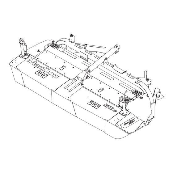
PRODUCT OVERVIEW 2.2 Component Identification Figure 2.1: 13-Foot SP Disc Header A - Front Curtains B - Cutterbar Doors C - Drive Shield (Left) D - Hose Support 1 E - Hydraulic Motor 2 F - Hose Support G - Center-Link Tube H - Hazard / Brake Lights J - Disc Drum (Right) K- Conditioner Rolls... - Page 30 PRODUCT OVERVIEW Figure 2.2: 13-Foot SP Disc Header A - Header Boots B - Side Deflectors C - Side Deflector Adjuster Handles D - Rear Crop Baffle E - Carrier Frame F - Shield (Right) 214077 Revision A...
-
Page 31: Definitions
ORFS This style of fitting is also commonly called ORS, which stands for O-ring seal R1 Series header MacDon R113 and R116 disc headers RoHS (Reduction of A directive by the European Union to restrict use of certain hazardous substances... - Page 32 PRODUCT OVERVIEW Term Definition Axial load placed on a bolt or screw, usually measured in Newtons (N) or Tension pounds (lb.) TFFT Turns from finger tight The product of a force X lever arm length, usually measured in Newton-meters (Nm) Torque or foot-pounds (lbf∙ft) A tightening procedure where fitting is assembled to a precondition (finger tight) and...
-
Page 33: Chapter 3: Operation
3 Operation 3.1 Break-In Period After attaching the self-propelled disc header to the self-propelled windrower for the first time, operate the machine slowly for five minutes, watching and listening from the self-propelled windrower seat for binding or interfering parts. NOTE: Until you become familiar with the sound and feel of your new self-propelled disc header, be extra alert and attentive. -
Page 34: Daily Start-Up Check
OPERATION 3.2 Daily Start-Up Check Perform the following checks each day before startup: CAUTION • Ensure windrower and self-propelled disc header are properly attached, all controls are in neutral, and windrower brakes are engaged. • Clear the area of other persons, pets etc. Keep children away from machinery. Walk around the self- propelled disc header to make sure no one is under, on, or close to it. - Page 35 OPERATION 1. Check the machine for leaks or any parts that are missing, broken, or not working correctly. NOTE: Use proper procedure when searching for pressurized fluid leaks. Refer to Hydraulic Hoses and Lines, page 163. 2. Clean all lights and reflective surfaces on the machine, and check lights for proper operation.
-
Page 36: Engaging And Disengaging Header Safety Props
OPERATION 3.3 Engaging and Disengaging Header Safety Props Safety props are located on both header lift cylinders on the windrower. Refer to relevant procedure for your windrower: • M1 Series Self-Propelled Windrowers 3.3.1 Engaging and Disengaging Header Safety Props: M1170 Windrower, page 24 •... -
Page 37: Engaging And Disengaging Header Safety Props: M155E4 Windrower
OPERATION 4. Disengage safety props by turning lever (A) away from header to raise safety prop until lever locks into vertical position. NOTE: If safety prop will not disengage, raise header to release the prop. 5. Repeat for opposite cylinder. CAUTION Check to be sure all bystanders have cleared the area. - Page 38 OPERATION 3. Pull lever (A) and rotate toward header to lower safety prop (B) onto cylinder. Repeat for opposite cylinder. Figure 3.8: Safety Prop Disengage safety props as follows: 1. Turn lever (A) away from header to raise safety prop until lever locks into vertical position.
-
Page 39: Header Float
OPERATION 3.4 Header Float The M1170 and M155E4 windrowers have different float adjustments. Although they both have float springs, the M1170 is completely adjustable from the cab through the Harvest Performance Tracker (HPT) and the M155E4 has coarse adjustment done at the spring drawbolt and fine adjustment done through the Cab Display Module (CDM) in the windrower cab. -
Page 40: Attaching Header To Windrower
OPERATION 3.5 Attaching Header to Windrower 3.5.1 Attaching R1 SP Disc Header to M1170 Windrower The windrower hydraulic center-link may be equipped with a self-aligning option that allows the Operator to control the vertical position of the center-link from the cab. DANGER To avoid bodily injury or death from unexpected startup of the machine, always stop the engine and remove the key from the ignition before leaving the operator’s seat for any reason. - Page 41 OPERATION CAUTION To prevent damage to the header lift linkages when lowering header lift legs without a header or weight box attached to the windrower, ensure the float springs tension is fully released. NOTE: If not prompted by the Harvest Performance Tracker (HPT) display to remove float, remove float manually.
- Page 42 OPERATION 8. Hydraulic center-link with optional self-alignment: a. Adjust position of the center-link cylinder (A) with the switches on the GSL until the hook (B) is above the header attachment pin. IMPORTANT: Hook release (C) must be down to enable self-locking mechanism.
- Page 43 OPERATION 10. Press the HEADER UP switch (A) to raise header to maximum height. NOTE: If one end of the header does NOT fully raise, rephase the lift cylinders as follows: a. Press and hold the HEADER UP switch (A) until both cylinders stop moving.
-
Page 44: Attaching R1 Series Sp Disc Header To M155E4 Windrower: Self-Aligning Hydraulic Center-Link
OPERATION 14. Disengage safety prop by turning lever (A) downward to raise safety prop until lever locks into vertical position. NOTE: If safety prop will not disengage, raise header slightly. 15. Repeat for opposite side. CAUTION Check to be sure all bystanders have cleared the area. Figure 3.20: Cylinder Safety Prop 16. - Page 45 OPERATION CAUTION To prevent damage to the lift system when lowering header lift linkages without a header or weight box attached to the windrower, ensure the float engagement pin is installed in storage position (B) and NOT in engaged position (A). CAUTION Check to be sure all bystanders have cleared the area.
- Page 46 OPERATION 4. Drive the windrower slowly forward until the windrower feet (A) enter the header supports (B). Continue driving slowly forward until the feet engage the supports and the header nudges forward. Figure 3.26: Header Support 5. Use the following GSL functions to position the center-link hook above the header attachment pin: •...
- Page 47 OPERATION 9. Press the HEADER UP switch (A) to raise header to maximum height. NOTE: If one end of the header does NOT fully raise, rephase the lift cylinders as follows: • Press and hold the HEADER UP switch until both cylinders stop moving.
- Page 48 OPERATION 11. Install clevis pin (A) through support and windrower lift member, and secure with hairpin (B). Repeat for opposite side. IMPORTANT: Ensure clevis pin (A) is fully inserted and hairpin is installed behind bracket. Figure 3.31: Header Support 12. Remove clevis pin from storage position (B) in linkage and insert into hole (A) to engage float springs.
-
Page 49: Attaching R1 Series Sp Disc Header To M155E4 Windrower: Hydraulic Center-Link Without Self-Alignment
OPERATION 15. Start the engine and activate the HEADER DOWN switch (A) on the GSL to fully lower the header. 16. Stop engine and remove key from ignition. Figure 3.34: Ground Speed Lever 3.5.3 Attaching R1 Series SP Disc Header to M155E4 Windrower: Hydraulic Center-Link without Self-Alignment 1. - Page 50 OPERATION IMPORTANT: Before starting engine, remove protective cover from exhaust stack. 2. Start the engine and activate the HEADER DOWN button (A) on the ground speed lever (GSL) to fully retract header lift cylinders. Figure 3.37: Ground Speed Lever 3. Relocate pin (A) in frame linkage as required to raise the center-link (B) until the hook is above the attachment pin on the header.
- Page 51 OPERATION 5. Use the following GSL functions to position the center-link hook above the header attachment pin: • HEADER TILT UP (A) to retract the center-link • HEADER TILT DOWN (B) to extend the center-link 6. Stop engine and remove key from ignition. Figure 3.40: Ground Speed Lever 7.
- Page 52 OPERATION 11. Engage safety props on both lift cylinders as follows: a. Stop engine and remove key from ignition. b. Pull lever (A) and rotate towards the header to release and lower safety prop (B) onto the lift cylinder. c. Repeat for opposite lift cylinder. Figure 3.43: Safety Prop 12.
- Page 53 OPERATION 13. Remove clevis pin from storage position (B) in linkage and insert into hole (A) to engage float springs. Secure with hairpin. Figure 3.45: Header Float Linkage 14. Disengage safety prop by turning lever (A) downwards to release and lower stop until lever locks into vertical position.
-
Page 54: Attaching Hydraulics And Electrical Connections
Connecting R1 Series Hydraulics and Electrical: M155E4 Windrowers, page 44 Connecting R1 Series Hydraulics and Electrical: M1170 Windrowers NOTE: Hydraulic drive kit (A) (MD #B6271) is required for a R113 13-foot self-propelled disc header to operate correctly on a M1170 Self-Propelled Windrower. To order this kit, contact your MacDon Dealer. - Page 55 OPERATION 3. Attach hose support (A) to windrower frame near left cab-forward leg, and route hose bundle under frame. NOTE: Route hoses as straight as possible and avoid rub/wear points that could damage hydraulic hoses. Figure 3.50: Hose Support Attachment 4.
-
Page 56: Connecting R1 Series Hydraulics And Electrical: M155E4 Windrowers
OPERATION 7. Remove protective plugs (A) from return line fitting (B) and pressure line fitting (C). IMPORTANT: Keep open lines and ports clean. Figure 3.53: Protective Plugs 8. Connect hydraulic hoses and electrical harness to receptacles on windrower as follows: a. - Page 57 OPERATION NOTE: Hydraulic drive kit (A) (MD #B6272) is required for a R113 self-propelled disc header to operate correctly on a M155E4 Self-Propelled Windrower. To order this kit, contact your MacDon Dealer. Figure 3.55: Hydraulic Drive Kit (MD #B6272) 1. Disengage and rotate lever (A) counterclockwise to FULLY UP position.
- Page 58 OPERATION 3. Move hose bundle (A) from the windrower and rest the bundle on the header. Figure 3.57: Hose Bundle 4. Position the hose support with lower bolt (A) in the forward hole as shown in Figure 3.58, page 46. Loosen both bolts and adjust as required.
- Page 59 OPERATION 6. Move the windrower’s left-side (cab-forward) platform (A) to the OPEN position. Refer to your windrower operator’s manual for instructions. Figure 3.60: Windrower Left Platform in Open Position 7. Route the windrower hose bundle (A) through hose support (B) on the header. NOTE: Route hoses as straight as possible and avoid rub/wear points that could damage hydraulic hoses.
- Page 60 OPERATION 9. Remove protective plugs (A) from return line fitting (B) and pressure line fitting (C). IMPORTANT: Keep open lines and ports clean. Figure 3.62: Protective Plugs 10. Connect the pressure hose (A) routed from the header to port M2 on the windrower’s disc drive valve (middle block).
- Page 61 OPERATION 11. Remove caps and plugs from hoses on windrower and lines on header. 12. Connect the return hose (B) from port M1 on the windrower’s drive manifold to the steel line attached to port (A) on the header motor. Figure 3.64: Hydraulic Connections 13.
- Page 62 OPERATION NOTE: If the windrower is equipped with a reverser valve (A) for an auger header, route the return hose (B) from port R1 on the windrower’s reverser valve to the steel line attached to port (C) on the header’s motor. Figure 3.66: Windrower Hose Connections with Reverser 15.
- Page 63 OPERATION 16. Connect the electrical harness (A) from windrower to the electrical connector (B) on the header. Figure 3.68: Electrical Connection 17. Lower and lock lever (A). Secure hose (B) with three cinch straps (C). Figure 3.69: Hose Bundle 214077 Revision A...
- Page 64 OPERATION 18. Move platform (A) to the CLOSED position. Figure 3.70: Top View of Windrower 214077 Revision A...
-
Page 65: Detaching The Header
OPERATION 3.6 Detaching the Header 3.6.1 Detaching R1 Series Header: M1170 Windrower DANGER To avoid bodily injury or death from unexpected startup of the machine, always stop the engine and remove the key from the ignition before leaving the operator’s seat for any reason. CAUTION Check to be sure all bystanders have cleared the area. - Page 66 OPERATION 5. Disconnect the following electrical harness and hydraulic hoses from the windrower: a. Disconnect the return hose from receptacle (A). b. Disconnect the pressure hose from receptacle (B). c. Disconnect the case drain hose from receptacle (C). d. Disconnect the electrical harness from receptacle (D).
- Page 67 OPERATION 7. Store the hydraulic hoses (A) and electrical harness (B) disconnected from the windrower in Step 5, page 54 the header’s hydraulic storage plate (C). NOTE: Install caps and plugs on open lines to prevent buildup of dirt and debris while in storage. Figure 3.75: Hydraulic Storage Plate (Parts Removed for Clarity) 8.
- Page 68 OPERATION 9. Engage safety prop on lift cylinder as follows: a. Pull lever (A) and rotate toward header to release, and lower safety prop onto cylinder. b. Repeat for opposite lift cylinder. IMPORTANT: Ensure the safety props engage over the cylinder piston rods.
- Page 69 OPERATION NOTE: If not prompted by the HPT to remove float, remove float manually. 14. Lower the header to the ground. Self-aligning center-link: 15. Use HEADER TILT cylinder switches (A) on GSL to release load on center-link cylinder. 16. Operate the link lift cylinder with the REEL UP switch (B) to disengage the center-link from the header.
-
Page 70: Detaching R1 Series Header: M155E4 Windrower
OPERATION 20. Back the windrower slowly away from header. 21. Reinstall clevis pin (A) through support (C) and secure with hairpin (B). Repeat for opposite side. Figure 3.82: Header Support 3.6.2 Detaching R1 Series Header: M155E4 Windrower DANGER To avoid bodily injury or death from unexpected startup of the machine, always stop the engine and remove the key from the ignition before leaving the operator’s seat for any reason. - Page 71 OPERATION 4. Disconnect hose (A) from port (M2) on the disc drive valve. Figure 3.84: Hydraulic Connections 5. Raise lever (A) and undo the three cinch straps (C). 6. Move hose (B) to store on header. Figure 3.85: Hose Bundle 214077 Revision A...
- Page 72 OPERATION 7. Disconnect the following hoses from the hydraulic motor: • Return hose (A) • Pressure hose (B) • Case drain hose (C) 8. Install caps on the connectors and hose ends (if equipped) to prevent buildup of dirt and debris. Figure 3.86: Hose Bundle 9.
- Page 73 OPERATION 10. Move the hose bundle from header to the left-side (cab-forward) hose support (B). 11. Rotate lever (A) clockwise and push to engage bracket. 12. Route the electrical harness through the hose support (B) and attach cap to electrical connector (C). Figure 3.88: Hose Bundle 13.
-
Page 74: Driveshields
OPERATION 3.7 Driveshields 3.7.1 Opening Driveshields CAUTION Do NOT operate the machine without the driveshields in place and secured. NOTE: Images shown are for left driveshield—right driveshield is similar. Figure 3.90: Left Driveshield 1. Remove lynch pin (A) and tool (B) from pin (C). Figure 3.91: Left Driveshield 214077 Revision A... -
Page 75: Closing Driveshields
OPERATION 2. Insert flat end of tool (A) into latch (B) and turn it counterclockwise to unlock. Figure 3.92: Driveshield Latch 3. Pull top of driveshield (A) away from header to open. NOTE: For improved access, lift driveshield off the pins at the base of the shield, and lay the shield on the header. - Page 76 OPERATION 1. Position driveshield onto pins at base of driveshield (if necessary). 2. Push driveshield (A) to engage latch (B). 3. Check that driveshield is properly secured. Figure 3.94: Left Driveshield 4. Replace tool (B) and lynch pin (A) on pin (C). Figure 3.95: Left Driveshield 214077 Revision A...
-
Page 77: Cutterbar Doors
OPERATION 3.8 Cutterbar Doors WARNING Do NOT operate the machine without all the cutterbar doors down or without curtains installed and in good condition. Two doors (A) with rubber curtains provide access to the cutterbar area. Curtains (B) and (C) are attached to each front corner and at the center respectively. -
Page 78: Opening Cutterbar Doors: Export Latches
OPERATION 1. Lift door (A) at front to open. Figure 3.98: Cutterbar Doors 3.8.3 Opening Cutterbar Doors: Export Latches Headers sold outside North America require a tool-operated latch on the cutterbar doors. Follow these steps to open cutterbar doors with export latches: DANGER To avoid bodily injury or death from unexpected startup of machine, always stop engine and remove key from ignition before leaving operator’s seat for any reason. - Page 79 OPERATION 2. Use a rod or screwdriver to press down on the latch (A) and release the cutterbar door. Figure 3.100: Cutterbar Door Latch (Cut Away View) 3. Lift up on door (A) while pressing down on latch. Figure 3.101: Left Cutterbar Door Open 214077 Revision A...
-
Page 80: Closing Cutterbar Doors
OPERATION 3.8.4 Closing Cutterbar Doors CAUTION To avoid injury, keep hands and fingers away from corners of doors when closing. 1. Pull door (A) at top to close. 2. Ensure that curtains hang properly and completely enclose cutterbar area. Figure 3.102: Cutterbar Doors 214077 Revision A... -
Page 81: Cutterbar Deflectors
OPERATION 3.9 Cutterbar Deflectors Cutterbar deflectors attach to the cutterbar just below the header’s conditioner rolls. Deflectors provide improved feeding into the conditioner rolls and prevent heavy crop with long stems from feeding under the rolls during cutting. Cutterbar deflectors may not be well-suited for some environments, such as sandy conditions, and can be easily removed or installed in the field. - Page 82 OPERATION 4. Position left deflector (A) on top of ledge along the aft end of the cutterbar, and align existing fasteners and cutterbar plug with slots in deflector (A). 5. Install three button hex head socket M10 bolts (B) with lock nuts in the holes with the heads facing down.
-
Page 83: Cutting Height
OPERATION 3.10 Cutting Height Cutting height is determined by a combination of the cutterbar angle and skid shoe settings. Adjust cutting height for optimum cutting performance while preventing excessive build-up of mud and soil inside the self-propelled disc header that can lead to poor crop flow and increased wear on cutting components. To choose an angle that maximizes performance for your crop and field conditions, refer to 3.11 Cutterbar Angle, page... -
Page 84: Cutterbar Angle
OPERATION 3.11 Cutterbar Angle The cutterbar angle adjustment ranges from 0 to 8 degrees below horizontal. Choose an angle that maximizes performance for your crop and field conditions. A flatter angle provides better clearance in stony conditions, whereas a steeper angle is required in down crops for better lifting action. Refer to your windrower operator’s manual for instructions. -
Page 85: Cutterbar Lubrication
OPERATION 3.12 Cutterbar Lubrication 3.12.1 Checking and Adding Cutterbar Lubricant DANGER To avoid bodily injury or death from unexpected startup of machine, always stop engine and remove key from ignition before leaving operator’s seat for any reason. CAUTION Exercise caution when working around the blades. Blades are sharp and can cause serious injury. Wear gloves when handling blades. - Page 86 OPERATION 6. Remove oil level inspection plug (A) and O-ring (B) from cutterbar. Figure 3.109: Cutterbar 7. Oil level must be up to the bore. If required, add lubricant as follows: a. Replace inspection plug removed in Step 6, page b.
-
Page 87: Draining Cutterbar
OPERATION 8. Check O-ring (B) for breaks or cracks and replace if necessary. 9. Install plug (A) and O-ring (B). Tighten securely. Figure 3.111: Cutterbar 3.12.2 Draining Cutterbar DANGER To avoid bodily injury or death from unexpected startup of the machine, always stop the engine and remove the key from the ignition before leaving the operator’s seat for any reason. -
Page 88: Filling Cutterbar
OPERATION NOTE: Do NOT flush the cutterbar. 6. Dispose of used lubricant safely. 3.12.3 Filling Cutterbar CAUTION Exercise caution when working around the blades. Blades are sharp and can cause serious injury. Wear gloves when handling blades. 1. Remove M18 cutterbar breather (A) from the raised end of cutterbar and add the exact amount of lubricant specified for the cutterbar. -
Page 89: Curtains
OPERATION 3.13 Curtains Rubber curtains are installed at the following locations: • Inboard curtain (A) attached to the center fixed cover. • Door curtains (B) attached to each cutterbar door. • Outboard curtains (C) attached to each front corner. The curtains form a barrier that minimizes the risk of thrown objects being ejected from the cutterbar area. -
Page 90: Removing Cutterbar Door Curtains
OPERATION 3.13.2 Removing Cutterbar Door Curtains The procedure for removing cutterbar door curtains is the same for both doors. 1. Open cutterbar doors (A). Refer to 3.8.2 Opening Cutterbar Doors, page Figure 3.116: Cutterbar Doors 2. Remove seven nuts (A) from the bolt studs. 3. -
Page 91: Installing Cutterbar Door Curtains
OPERATION 3.13.3 Installing Cutterbar Door Curtains The procedure for installing cutterbar door curtains is the same for both doors. 1. Insert the cutterbar door stud bolts (B) into the precut holes on curtain (A). 2. Install seven large washers (C). 3. -
Page 92: Installing Cutterbar Inboard Curtain
OPERATION 3. Remove four nuts (A) from weld studs on center shield, remove two curtain brackets (B), and remove curtain. Figure 3.121: Inboard Curtain, Nuts, and Brackets 3.13.5 Installing Cutterbar Inboard Curtain 1. Open cutterbar doors (A). Refer to 3.8.2 Opening Cutterbar Doors, page Figure 3.122: Cutterbar Doors 2. -
Page 93: Removing Outboard Curtains
OPERATION 4. Secure two curtain brackets (A) to center shield using two M10 carriage head bolts (B) and nuts. 5. Torque bolts (A) to 39 Nm (29 lbf·ft). Figure 3.124: Inboard Curtain and Brackets 3.13.6 Removing Outboard Curtains The procedure for removing outboard curtains is the same for both sides. 1. -
Page 94: Installing Outboard Curtains
OPERATION 3. Remove two nuts (A) from bolt studs. 4. Remove nut (B) from carriage head bolt, slide out the bracket (C), and remove curtain (D). Figure 3.127: Outboard Curtain 3.13.7 Installing Outboard Curtains The procedure for installing outboard curtains is the same for both sides. 1. - Page 95 OPERATION 6. Install four bolts, large washers, and nuts (A) to secure outboard curtain (B) to endsheet. Torque bolts to 39 Nm (29 lbf·ft). Figure 3.130: Left Side Endsheet 214077 Revision A...
-
Page 96: Roll Gap
OPERATION 3.14 Roll Gap The roll gap controls the degree to which crop is conditioned as it passes through the rolls. Roll gap is factory-set at 6 mm (1/4 in.) for steel rolls, and approximately 3 mm (1/8 in.) for polyurethane rolls. Polyurethane rolls are better suited for crushing stems while providing reduced crimping and are recommended for alfalfa, clover, legumes and similar crops. -
Page 97: Adjusting Roll Gap: Polyurethane Rolls
OPERATION 4. Steel Rolls: The length of thread (A) extending above the jam nut on the adjustment rods can be used as an approximation of roll gap but does NOT provide consistent roll gap measurements. Roll gap factory setting is 6 mm (1/4 in.). Refer to 3.14.3 Adjusting Roll Gap: Steel Rolls, page Figure 3.132: Roll Gap Adjustment... -
Page 98: Adjusting Roll Gap: Steel Rolls
OPERATION 3.14.3 Adjusting Roll Gap: Steel Rolls The length of thread extending above the jam nut on the adjustment rods can be used as an approximation of roll gap but does NOT provide consistent roll gap measurements. To ensure roll gap is at the factory setting, follow the procedure below. -
Page 99: Roll Tension
OPERATION 3.15 Roll Tension Roll tension (the pressure holding the rolls together) is factory-set to maximum and is adjustable. Heavy crops or tough forage can cause the rolls to separate; therefore, maximum roll tension is required to ensure that materials are sufficiently crimped. To prevent over-conditioning of light alfalfa and short grasses, apply less roll tension. -
Page 100: Roll Timing
OPERATION 3.16 Roll Timing For proper conditioning, the rolls must be properly timed with the bar on one roll centered between two bars on the other roll. The factory setting should be suitable for most crop conditions. IMPORTANT: Roll timing is critical when the roll gap is decreased because conditioning is affected, and the bars may contact each other. - Page 101 OPERATION NOTE: When setting roll timing, ensure the grease fittings (F) on both drivelines face towards the rear simultaneously. 2. Secure bottom roll (A). 3. Manually rotate the upper roll (B) in a counterclockwise direction until it stops. 4. Make a mark (C) across the yoke (D) and gearbox flange (E).
- Page 102 OPERATION 6. Determine the center point (A) between the two marks on the yoke plate, and place a third mark. 7. Rotate the upper roll (B) in the counterclockwise direction until the bolt lines up with the third (center) mark. Figure 3.140: Conditioner Drive 8.
-
Page 103: Roll Conditioner
OPERATION 3.17 Roll Conditioner WARNING Keep everyone several hundred feet away from your operation. Ensure bystanders are never in line with the front or rear of the machine. Stones or other foreign objects can be ejected from either end with force. A wider windrow will generally dry faster and more evenly, resulting in less protein loss. -
Page 104: Positioning Forming Shield Rear Baffle: Roll Conditioner
OPERATION 3.17.2 Positioning Forming Shield Rear Baffle: Roll Conditioner DANGER To avoid bodily injury or death from unexpected startup of machine, always stop engine and remove key from ignition before leaving operator's seat for any reason. The rear baffle primarily determines the height of the windrow, but can also affect the width. It is located immediately behind and above the conditioning rolls and can be positioned to do the following: •... -
Page 105: Haying Tips
OPERATION 3.18 Haying Tips 3.18.1 Curing Curing crops quickly helps maintain the highest quality of crop material as 5% of protein is lost from hay for each day that it lays on the ground after cutting. Leaving the windrow as wide and fluffy as possible results in the quickest curing. Cured hay should be baled as soon as possible. -
Page 106: Windrow Characteristics
OPERATION 3.18.4 Windrow Characteristics Producing windrows with the recommended characteristics will achieve the greatest results. Refer to 3 Operation, page 21 for instructions on adjusting the header. Table 3.2 Recommended Windrow Characteristics Characteristic Advantage Enables airflow through windrow, which is more important to the curing High and fluffy process than direct sunlight Consistent formation (not bunching) -
Page 107: Transporting The Header
OPERATION 3.19 Transporting the Header For information on transporting the header when attached to the windrower, refer to your windrower operator’s manual. IMPORTANT: For cab-forward road travel the windrower must have the lighting and marking bundle installed (MD #B5412). 214077 Revision A... -
Page 109: Chapter 4: Maintenance And Servicing
4 Maintenance and Servicing The following instructions provide information about routine header service. Detailed maintenance and service information is contained in the technical manual that is available from your Dealer. A parts catalog is located in a plastic case at the right end of the header. Log hours of operation and use the maintenance record provided (refer to 4.3.1 Maintenance Schedule/Record, page... -
Page 110: Recommended Safety Procedures
MAINTENANCE AND SERVICING 4.2 Recommended Safety Procedures • Park on level surface when possible. Follow all recommendations in your tractor operator's manual. • Wear close-fitting clothing and cover long hair. Never wear dangling items such as scarves or bracelets. Figure 4.1: Safety Around Equipment •... - Page 111 MAINTENANCE AND SERVICING • Be prepared if an accident should occur. Know where the first aid kits and fire extinguishers are located, and know how to use them. Figure 4.4: Safety Equipment • Keep the service area clean and dry. Wet or oily floors are slippery.
-
Page 112: Maintenance Requirements
MAINTENANCE AND SERVICING 4.3 Maintenance Requirements Regular maintenance is the best insurance against early wear and untimely breakdowns. Following the maintenance schedule will increase your machine’s life. Periodic maintenance requirements are organized according to service intervals. When servicing the machine, refer to the specific headings in this section. Refer to the inside back cover of this manual and use only the fluids and lubricants specified. -
Page 113: Maintenance Schedule/Record
MAINTENANCE AND SERVICING 4.3.1 Maintenance Schedule/Record Keep a record of maintenance as evidence of a properly maintained machine. Daily maintenance records are not required to meet normal warranty conditions. ü ü Check S S Lubricate ▲ Change Action Hour meter reading Service date Serviced by First Use... - Page 114 MAINTENANCE AND SERVICING ü ü Check S S Lubricate ▲ Change Action Lube roller conditioner bearings. Refer 4.4 Lubrication, page 105. Lube conditioner roll driveline slip joints. Refer to 4.4 Lubrication, page 105. First 50 hours Check conditioner drive belt tension. ü...
-
Page 115: Break-In Inspections
MAINTENANCE AND SERVICING ü ü Check S S Lubricate ▲ Change Action Change roll timing gearbox lubricant. ▲ Refer to Checking and Changing Roll Timing Gearbox Oil, page 161. Change header drive gearbox ▲ lubricant. Refer to 4.6.1 Checking and Adding Lubricant, page 156. -
Page 116: Preseason Servicing
MAINTENANCE AND SERVICING 4.3.3 Preseason Servicing CAUTION • Review the operator's manual to refresh your memory on safety and operating recommendations. • Review all safety signs and other decals on the self-propelled disc header and note hazard areas. • Ensure all shields and guards are properly installed and secured. Never alter or remove safety equipment. -
Page 117: Lubrication
MAINTENANCE AND SERVICING 4.4 Lubrication WARNING To avoid personal injury, before servicing header or opening drive covers, refer to 4.1 Preparing Machine for Servicing, page Greasing points are marked on the machine by decals showing a grease gun and the grease interval in hours of operation. -
Page 118: Service Intervals
MAINTENANCE AND SERVICING 4.4.2 Service Intervals NOTE: Use high temperature extreme pressure (EP2) performance with 1% max molybdenum disulphide (NLGI Grade 2) lithium base unless otherwise specified. First 25 Hours To check conditioner roll timing gearbox oil level, refer to Checking and Changing Roll Timing Gearbox Oil, page 161. -
Page 119: Every 25 Hours
MAINTENANCE AND SERVICING Every 25 Hours Figure 4.8: Every 25 Hours A - Idler Pivot B - Bearing, Roller Conditioner (4 Places) C - U-Joint, Upper Driveline (2 Places) D - Slip Joints, Conditioner Drivelines 5 E - U-Joint, Lower Driveline (2 Places) F - Conditioner Drive Belt Tensioner 5. -
Page 120: First 50 Hours
MAINTENANCE AND SERVICING First 50 Hours To change conditioner roll timing gearbox oil level, refer to Checking and Changing Roll Timing Gearbox Oil, page 161. Figure 4.9: First 50 Hours A – Conditioner Drive Belt Tensioner B – Header Drive Gearbox C –... -
Page 121: Every 100 Hours Or Annually
MAINTENANCE AND SERVICING Every 100 Hours or Annually Figure 4.10: Every 100 Hours A – Conditioner Drive Belt Tensioner B – Conditioner Roll Timing Gearbox C – Header Drive Gearbox 214077 Revision A... -
Page 122: First 150 Hours
MAINTENANCE AND SERVICING First 150 Hours Figure 4.11: First 150 Hours A – Header Drive Gearbox B – Cutterbar C – Conditioner Roll Timing Gearbox 214077 Revision A... -
Page 123: Every 250 Hours
MAINTENANCE AND SERVICING Every 250 Hours Figure 4.12: Every 250 Hours A – Header Drive Gearbox B – Cutterbar C – Conditioner Roll Timing Gearbox 214077 Revision A... -
Page 124: Cutterbar
MAINTENANCE AND SERVICING 4.5 Cutterbar The cutterbar does not require regular maintenance other than checking and changing the lubricant at regular intervals. Refer to 4.3.1 Maintenance Schedule/Record, page 101. IMPORTANT: Check the lubricant level when the lubricant is warm. If the lubricant is cold, idle the machine for about 10 minutes prior to checking. -
Page 125: Removing Cutterbar Discs
MAINTENANCE AND SERVICING 1. Ensure that the discblade fasteners (A) are securely attached to the cutterbar disc and that nut shields (B) are present and undamaged. Replace as required. 2. Check that the cutterbar disc bolts (C) are securely attached to the spindles. Tighten as required. 3. -
Page 126: Installing Cutterbar Discs
MAINTENANCE AND SERVICING 4. Place a pin (or equivalent) in the front hole of the rock guard (B) to prevent disc rotation while loosening bolts. 5. Remove four M12 bolts (A) and washers. Figure 4.16: Cutterbar Disc Bolts 6. Remove cutterbar disc cap (A). 7. - Page 127 MAINTENANCE AND SERVICING 1. Install spacer plate (A) on spindle. Figure 4.18: Cutterbar Disc and Cap 2. Place a pin (or equivalent) in the front hole of the rock guard (D) to prevent disc rotation while tightening bolts. 3. Position new disc (A) on spindle ensuring that it is positioned at a 90 degree angle in relation to the adjacent discs.
-
Page 128: Cutterbar Spindles
MAINTENANCE AND SERVICING 4.5.2 Cutterbar Spindles Discs are factory-installed to produce three crop stream, but disc rotation patterns can be changed to suit crop conditions. To prevent damage to the cutterbar and drive systems, each disc is attached to a spindle containing a shear pin (A). If the disc contacts a large object such as a stone or stump, the pin will shear and the disc will stop rotating and move upwards while remaining attached to the spindle with a... - Page 129 MAINTENANCE AND SERVICING CAUTION Discblades have two sharp cutting edges that can cause serious injury. Exercise caution and wear gloves when working with blades. 1. Park on a flat, level surface. 2. Lower self-propelled disc header fully, shut off engine, and remove key. NOTE: To prevent oil from spilling from the cutterbar when removing disc spindles, ensure self-propelled disc header is on a flat, level surface and is tilted all the way.
- Page 130 MAINTENANCE AND SERVICING 6. Remove cutterbar disc cap (A). 7. Remove cutterbar disc (B). IMPORTANT: Blades are rotation specific. It is necessary to switch entire disc when swapping spindles. Figure 4.25: Cutterbar Disc and Cap 8. Remove spacer plate (A). Figure 4.26: Spacer Plate 9.
-
Page 131: Installing Cutterbar Spindles
MAINTENANCE AND SERVICING 10. Remove spindle (A) from cutterbar. Figure 4.28: Left Spindle Installing Cutterbar Spindles Figure 4.29: Underside of Cutterbar Spindles Installed in Cutterbar IMPORTANT: Right discs (A) and left discs (B) are timed and must be at 90° when reinstalled. Misaligned discs could result in the following: •... - Page 132 MAINTENANCE AND SERVICING NOTE: Right discs (A) and left discs (B) are slightly offset as shown depending on which idler gear the spindle is turning. • Spindles that rotate clockwise have left-leading threading • Spindles that rotate counterclockwise have right-leading threading DANGER To avoid bodily injury or death from unexpected start-up or fall of a raised machine, stop engine, remove key, and engage windrower lift cylinder safety props before going under machine for any reason.
- Page 133 MAINTENANCE AND SERVICING 4. Determine suitable spindle rotation pattern for crop conditions. Refer to 4.5.2 Cutterbar Spindles, page 116. Figure 4.31: 13- and 16-Foot Cutterbars 5. Ensure that spindle O-ring (A) is properly seated, cleaned, and undamaged. Figure 4.32: Left-Hand Spindle O-Ring 6.
- Page 134 MAINTENANCE AND SERVICING 7. Insert studs (A) into spindle as shown. NOTE: Plugs are factory-installed as shown in position (B), but may come loose over time. Ensure studs are inserted into proper location. IMPORTANT: Ensure clockwise spindles rotate clockwise and counterclockwise spindles (with machined grooves) rotate counterclockwise.
- Page 135 MAINTENANCE AND SERVICING 10. Install spacer plate (A). Figure 4.37: Spacer Plate 11. Place a pin (or equivalent) in the front hole of the rock guard (D) to prevent disc rotation while tightening bolts. IMPORTANT: Blades are rotation specific. It is necessary to switch entire disc when swapping spindles.
-
Page 136: Cutterbar Crop Stream Configuration
MAINTENANCE AND SERVICING 4.5.3 Cutterbar Crop Stream Configuration Discs are factory-installed to produce three crop streams, but disc rotation pattern can be changed by substitution of spindle and corresponding disc to suit crop conditions. Each spindle and disc pair is designed to rotate in one direction and must be changed as sets when altering crop flows. -
Page 137: Changing 13-Foot Cutterbar Crop Stream Configuration
MAINTENANCE AND SERVICING Changing 13-Foot Cutterbar Crop Stream Configuration Figure 4.42: 13-Foot (8 Disc) Spindle Rotation Pattern and Crop Streams A - One Crop Stream B - Three Crop Streams NOTE: Refer to Removing Cutterbar Spindles, page 116 Installing Cutterbar Spindles, page 119. -
Page 138: Inspecting Discblades
MAINTENANCE AND SERVICING Inspecting Discblades DANGER To avoid bodily injury or death from unexpected startup of machine, always stop engine and remove key from ignition before leaving operator’s seat for any reason. CAUTION Discblades have two sharp cutting edges that can cause serious injury. Exercise caution and wear gloves when working with blades. -
Page 139: Inspecting Discblade Hardware
MAINTENANCE AND SERVICING IMPORTANT: The discblades have cutting edges on both sides so the blades can be turned over and reused. The twist in each blade determines the cutting direction. Figure 4.45: Counterclockwise Disc Rotation Direction Figure 4.46: Clockwise Disc Rotation Direction Inspecting Discblade Hardware CAUTION Damaged or loose discblades or blade attachment hardware can be ejected during machine operation and... - Page 140 MAINTENANCE AND SERVICING 1. Check and replace bolts under the following conditions: • Bolt has been removed and reinstalled five times. • Head (A) is worn flush with bearing surface of blade. • Diameter of bolt neck (B) has worn to 14.5 mm (9-1/16 in.) or less.
-
Page 141: Removing Discblades
MAINTENANCE AND SERVICING 2. Check and replace nuts under the following conditions: • Nut has been previously installed—nuts are one-time use only. • Nut shows signs of wear (A) that is more than half the original height (B). • Nut is cracked. Figure 4.48: Discblade Nut Removing Discblades DANGER... -
Page 142: Installing Discblades
MAINTENANCE AND SERVICING 4. Rotate disc (A) so that blade (B) faces forward and lines up with hole (C) in rock guard. Figure 4.50: Discblade Aligned with Hole in Rock Guard 5. Place a pin (or equivalent) in the front hole of the rock guard to prevent disc rotation while loosening blade bolts. -
Page 143: Accelerators
MAINTENANCE AND SERVICING 1. Place a pin (or equivalent) in the front hole of the rock guard to prevent disc rotation while tightening blade bolts. 2. Install new or reversed blade (A) with shoulder bolt (B) onto disc (C). IMPORTANT: Nuts are one-time-use only. -
Page 144: Inspecting Accelerators
MAINTENANCE AND SERVICING Inspecting Accelerators DANGER To avoid bodily injury or death from unexpected startup of machine, always stop engine and remove key from ignition before leaving operator’s seat for any reason. 1. Raise self-propelled disc header fully, stop engine, and remove key. 2. -
Page 145: Installing Accelerators
MAINTENANCE AND SERVICING 3. Remove nut (A), flange bolt (B), and discblade (C) from disc. Discard nut. Figure 4.56: Discblade and Disc 4. Remove lock nut (A), accelerator (B), blade holder (C), and hex-socket bolt (D). 5. Repeat the removal procedure for the second accelerator. -
Page 146: Rock Guards
MAINTENANCE AND SERVICING 3. Install new nut (A), flange bolt (B), and discblade (C) onto disc. Figure 4.59: Discblade and Disc 4. Torque the inside nut (A) to 58 Nm (43 lbf·ft). 5. Torque the outside nut (B), closest to the blade, to 125 Nm (92 lbf·ft). -
Page 147: Removing Rock Guards
MAINTENANCE AND SERVICING 1. Raise self-propelled disc header fully, stop engine, and remove key. 2. Engage windrower lift cylinder safety props. Refer to Engaging and Disengaging Header Safety Props, page 3. Inspect rock guards for wear, cracks, damage, or distortion. Replace if worn to 75% or more of their original thickness. -
Page 148: Installing Rock Guards
MAINTENANCE AND SERVICING Installing Rock Guards 1. Guide rock guard onto cutterbar until tabs (A) sit on top of the cutterbar while bottom back bolt holes line up. Figure 4.64: Rock Guard Installed on Cutterbar 2. Install two hex head screws, washers, and lock nuts (A). - Page 149 MAINTENANCE AND SERVICING 2. Open cutterbar doors (A). Refer to 3.8.2 Opening Cutterbar Doors, page Figure 4.66: Cutterbar Doors CAUTION Discblades have two sharp cutting edges that can cause serious injury. Exercise caution and wear gloves when working with blades. 3.
-
Page 150: Removing Driven Drums And Driveline
MAINTENANCE AND SERVICING 6. Close cutterbar doors (A). Refer to 3.8.4 Closing Cutterbar Doors, page Figure 4.68: Cutterbar Doors in Closed Position Removing Driven Drums and Driveline DANGER To avoid bodily injury or death from unexpected start-up or fall of a raised machine, stop engine, remove key, and engage windrower lift cylinder safety props before going under machine for any reason. - Page 151 MAINTENANCE AND SERVICING 2. Remove four M10 hex flange head bolts (A) and remove vertical drive shield (B). Figure 4.70: Vertical Drive Shield 3. Remove two M10 hex flange head bolts (A) and remove cover plate (B). Figure 4.71: Cover Plate 4.
- Page 152 MAINTENANCE AND SERVICING 5. Remove one 20 mm M10 hex flange head bolt (A), two 16 mm M10 hex flange head bolts (B), and vertical shield (C). Figure 4.73: Vertical Shield 6. Remove eight M8 hex flange head bolts (A), and remove two drum shields (B).
-
Page 153: Installing Driven Drums And Driveline
MAINTENANCE AND SERVICING 8. Slide driveline (A) downwards, tilt to the side, and pull driveline up and out of drum. NOTE: For clarity, illustration shows cutaway view of drum and tube shield. Figure 4.76: Vertical Driveline (Cutaway View Shown) 9. Look down into the drum, and use a 305 mm (12 in.) extension and 16 mm deep socket to remove the four M12 bolts (A) and washers holding the drum disc in place. - Page 154 MAINTENANCE AND SERVICING 1. Position the drum disc assembly as shown. 2. Use a 305 mm (12 in.) extension and 16 mm deep socket to install the four M12 bolts (A) and washers that hold the drum disc in place. Torque to 85 Nm (63 lbf·ft). Figure 4.78: Drum Disc (Top View, Arrow Indicates Front of Machine) 3.
- Page 155 MAINTENANCE AND SERVICING 7. Position two drum shields (B) as shown, and secure with eight M8 hex flange head bolts (A). Figure 4.81: Drum Shields 8. Position vertical shield (A) as shown, and install one 20 mm M10 hex flange head bolt (B) and two 16 mm M10 hex flange head bolts (C).
- Page 156 MAINTENANCE AND SERVICING 10. Install top M10 hex flange head bolt (B) through cover plate (A) and top plate (C). 11. Install lower M10 hex flange head bolt (D) through cover plate (A) and vertical shield (E). 12. Tighten bolts (B) and (D). Figure 4.84: Cover Plate 13.
-
Page 157: Removing Non-Driven Drums
MAINTENANCE AND SERVICING 14. Close cutterbar doors. Refer to 3.8.4 Closing Cutterbar Doors, page Figure 4.86: Cutterbar Doors in Closed Position Removing Non-Driven Drums DANGER To avoid bodily injury or death from unexpected start-up or fall of a raised machine, stop engine, remove key, and engage windrower lift cylinder safety props before going under machine for any reason. -
Page 158: Installing Non-Driven Drums
MAINTENANCE AND SERVICING 2. Place a wooden block between two cutterbar discs to prevent disc rotation while loosening blade bolts. 3. Remove eight M8 bolts (A) and washers securing the cover to the non-driven drum, and then remove the cover. Figure 4.88: Non-Driven Drum Cover (Top View) 4. - Page 159 MAINTENANCE AND SERVICING 1. Position each disc at a 90 degree angle relative to the neighboring discs. IMPORTANT: Discs are direction-specific. Ensure proper disc 90° orientation. NOTE: Arrow in illustration points to the front of the machine. Figure 4.90: Cutterbar Discs (Top View) 2.
- Page 160 MAINTENANCE AND SERVICING 5. Install eight M8 bolts (A) and washers to secure the cover to the non-driven drum, and torque to 28 Nm (20 lbf·ft). NOTE: Arrow in illustration points to the front of the machine. WARNING Ensure cutterbar is completely clear of foreign objects. Foreign objects can be ejected with considerable force when the machine is started and may result in serious injury or machine damage.
-
Page 161: Cutterbar Spindle Shear Pin
MAINTENANCE AND SERVICING 4.5.8 Cutterbar Spindle Shear Pin To prevent damage to the cutterbar and drive systems, each disc is attached to a spindle containing a shear pin (A). If the disc contacts a large object such as a stone or stump, the pin will shear and the disc will stop rotating and move upwards while remaining attached to the spindle with a snap ring (B). - Page 162 MAINTENANCE AND SERVICING 3. Open cutterbar doors (A). Refer to 3.8.2 Opening Cutterbar Doors, page 4. Clean debris from work area. Figure 4.96: Cutterbar Doors 5. Remove cutterbar disc (A). Refer to Removing Cutterbar Discs, page 113. 6. Remove driven drum (B). Refer to Removing Driven Drums and Driveline, page 138.
- Page 163 MAINTENANCE AND SERVICING 9. Remove M12 bolt and remove safecut spindle-nut wrench (A) from left side shield plate. Figure 4.99: Safecut Spindle-Nut Wrench Location 10. Identify left or right markings on spindle nut. IMPORTANT: Distinguish between left and right markings as follows: •...
-
Page 164: Installing Cutterbar Spindle Shear Pin
MAINTENANCE AND SERVICING 12. Use the safecut spindle-nut wrench and remove nut (A). Figure 4.102: Cutterbar Spindle 13. Remove the hub (A). 14. Remove shear pins (B). Do NOT damage the pin bore on the pinion. NOTE: Check the nut and hub for damage. Replace if necessary. - Page 165 MAINTENANCE AND SERVICING 1. Fill the space above the bearing with grease. 2. Place the hub (A) on the spindle (C). 3. Install shear pins (B). Figure 4.104: Cutterbar Spindle 4. Observe orientation of groove in shear pin (A). IMPORTANT: The correct shear pin orientation is critical.
- Page 166 MAINTENANCE AND SERVICING 6. Using the safecut spindle-nut wrench (B), torque spindle nut (C) to 300 Nm (221 lbf·ft). NOTE: Position the safecut spindle-nut wrench (B) 90 degrees (D) to the torque wrench (A). 7. Return safecut spindle-nut wrench to left side shield plate.
- Page 167 MAINTENANCE AND SERVICING 11. Install cutterbar disc (A). Refer to Installing Cutterbar Discs, page 114. 12. Install driven drum (B). Refer to Installing Driven Drums and Driveline, page 141. 13. Install non-driven drum (C). Refer to Installing Non- Driven Drums, page 146.
-
Page 168: Header Drive 90-Degree Gearbox
MAINTENANCE AND SERVICING 4.6 Header Drive 90-Degree Gearbox The header drive gearbox (A), transfers power from the hydraulic motor. It is located inside the drive compartment at the left end of the self-propelled disc header. The only regular servicing required is maintaining the lubricant level and changing the lubricant according to the intervals specified in this manual. -
Page 169: Conditioners
MAINTENANCE AND SERVICING 4.7 Conditioners 4.7.1 Conditioner Drive Belt The conditioner drive belt is located inside the left driveshield and is tensioned with a spring tensioner. The tension is factory-set and should not require adjustment. Inspecting Conditioner Drive Belt Check the belt tension and inspect for damage or wear every 100 hours or annually (preferably before the start of the cutting season). -
Page 170: Removing Conditioner Drive Belt
MAINTENANCE AND SERVICING 5. Measure the length of belt tensioner spring (A) and ensure spring length (B) is 366 mm (14-3/8 in.) in accordance with spring tension decal (C). If spring length requires adjustment, refer to Installing Conditioner Drive Belt, page 159. -
Page 171: Installing Conditioner Drive Belt
MAINTENANCE AND SERVICING 4. Turn jam nut (A) counterclockwise to unlock tension adjustment. 5. Turn jam nut (A) and adjuster nut (B) counterclockwise to fully collapse tensioner spring (C), and release the tension from conditioner drive belt (D). 6. Remove drive belt (D). Figure 4.118: Conditioner Drive Installing Conditioner Drive Belt DANGER... - Page 172 MAINTENANCE AND SERVICING 3. Measure the length of tensioner spring (C); dimension (D) should be set to 366 mm (14-3/8 in.). 4. Loosen nut (A). 5. To adjust the spring tension, turn adjuster nut (B) clockwise to increase spring length (tension) or turn adjuster nut (B) counterclockwise to decrease spring length (relax).
-
Page 173: Roll Timing Gearbox (Md #221748)
MAINTENANCE AND SERVICING 4.7.2 Roll Timing Gearbox (MD #221748) The roll timing gearbox, located inside the drive compartment at the right side of the self-propelled disc header, transfers power from the gearbox-driven lower roll to the upper roll. The gearbox (A) does not require routine maintenance or service other than checking and changing the oil. - Page 174 MAINTENANCE AND SERVICING Checking Conditioner Gearbox Oil Level 3. Clean around oil level plug (A) on inboard side of gearbox. 4. Remove oil level plug (A), and check that oil level is even with the hole. 5. Top up oil level with SAE 85W-140 gear oil if necessary. 6.
-
Page 175: Hydraulics
MAINTENANCE AND SERVICING 4.7.3 Hydraulics Hydraulic Hoses and Lines Check hydraulic hoses and lines daily for signs of leaks. WARNING • Avoid high-pressure fluids. Escaping fluid can penetrate the skin causing serious injury. Relieve pressure before disconnecting hydraulic lines. Tighten all connections before applying pressure. Keep hands and body away from pin holes and nozzles which eject fluids under high pressure. -
Page 176: Servicing Amber Hazard/Signal Lights
MAINTENANCE AND SERVICING Servicing Amber Hazard/Signal Lights Replacing Amber Hazard/Signal Bulb 1. Remove two Phillips screws (A) from fixture, and remove the plastic lens. 2. Replace bulb, and reinstall plastic lens and screws. Bulb—Trade #1157. Figure 4.128: Plastic Lens and Screws Replacing Amber Hazard/Signal Light Fixture 1. -
Page 177: Driveshields
MAINTENANCE AND SERVICING 4.7.5 Driveshields Removing Driveshields CAUTION Do NOT operate the machine without the driveshields in place and secured. NOTE: Images shown are for left side driveshield (A). Right side driveshield is similar. Figure 4.130: Left Driveshield 1. Remove lynch pin (A) and tool (B) from pin (C). Figure 4.131: Tool to Unlock Driveshield 214077 Revision A... -
Page 178: Installing Driveshields
MAINTENANCE AND SERVICING 2. Insert flat end of tool (A) into latch (B) and turn it counterclockwise to unlock. Figure 4.132: Tool to Unlock Driveshield and Latch 3. Pull top of driveshield (A) away from header conditioner and lift off the pins at the base of the shield to remove. Figure 4.133: Driveshield Installing Driveshields CAUTION... -
Page 179: Replacing Driveshield Latch
MAINTENANCE AND SERVICING 1. Position driveshield (A) onto pins (B) at base of driveshield. 2. Push driveshield to engage latch (C). 3. Check that driveshield (A) is properly secured. Figure 4.134: Driveshield and Latch 4. Replace tool (B) and lynch pin (A) on pin (C). Figure 4.135: Tool to Unlock Driveshield Replacing Driveshield Latch CAUTION... - Page 180 MAINTENANCE AND SERVICING 1. Remove driveshield (A). Refer to Removing Driveshields, page 165. Figure 4.136: Driveshield 2. Remove hex nut (A) and flat washer securing latch to backside of driveshield, replace latch if worn or damaged, and reinstall nut and washer. Figure 4.137: Backside of Driveshield 3.
-
Page 181: Conditioners
MAINTENANCE AND SERVICING 4.7.6 Conditioners Roll Conditioner Rolls condition the crop by crimping and crushing the stem in several places, which allows the release of moisture resulting in faster drying times. Both steel and polyurethane conditioner rolls are available. Refer to 5.1 Options and Attachments, page 181 for ordering information. -
Page 182: Changing The Conditioner
Bearings 4.7.7 Changing the Conditioner The R113 self-propelled disc header can be operated either with no conditioner, with a polyurethane roll conditioner, or with a steel roll conditioner. If the header is not conditioner equipped, a shield must be installed. - Page 183 MAINTENANCE AND SERVICING 3. M1170: Move hose bundle (A) clear of frame and lay on header. Figure 4.143: M1170 Hose Bundle 4. M155E4: Remove two bolts (A) attaching hose bracket (B) to header frame. Place hose bundle and bracket onto header. Do NOT disconnect hoses from motor.
- Page 184 MAINTENANCE AND SERVICING 6. To protect the finish on the frame, wrap packing foam (A) (or equivalent) around frame at approximate shown locations. 7. Position forks (B) under the packing foam on the frame as shown at right. Raise forks and lift frame slightly. The forks should not directly contact the frame.
-
Page 185: Installing The Conditioner
MAINTENANCE AND SERVICING 12. Loosen two M16 hex head bolts (A) at each side of conditioner that secure it to header. DANGER To prevent the conditioner from falling backward, ensure lifting chains are secure and tight. Failure to do so may result in death or serious injury. - Page 186 MAINTENANCE AND SERVICING 3. Carefully align pin (B) at each end of conditioner (A) with lug (C) on header. Lower the conditioner (A), so that pins (B) engage lugs (C) on header Figure 4.152: Installing Conditioner 4. Align mounting holes and install four M16 x 40 hex head bolts (A) with heads facing inboard (two per side).
- Page 187 MAINTENANCE AND SERVICING 10. Slowly move forward until the lift arm (C) is lined up with the mounting holes in the frame (A) and (B). Figure 4.155: Frame (Left Side Shown) 11. Install only bolt (A) through the frame (B) and bushing (D) in the lift arm.
-
Page 188: Installing Conditioner Drive
MAINTENANCE AND SERVICING 18. With flat washer shim (A) on either side of the center-link support, install securing bolt (B) and washer (C) through the conditioner center-link support bracket and center-link support. 19. Install nut (D) and torque to 332–346 Nm (245–255 lbf·ft). - Page 189 MAINTENANCE AND SERVICING 1. Remove drive cover (A) from left side of header by removing securing hex head bolt (B), flat washer (C) and nut (D) and sliding cover off pins (E). Figure 4.160: Drive Cover 2. Position tensioner assembly (A) as shown, and secure with M16 x 120 bolt (B) and nut (C).
-
Page 190: Shield (No Conditioner)
MAINTENANCE AND SERVICING 4.7.8 Shield (No Conditioner) Removing Shield (No Conditioner) Follow these steps to remove the shielding installed on a disc header configured without a conditioner: 1. Disconnect and remove the header from the windrower. On both ends of the header, remove four M16 hex head bolts (A), nuts, and flat washers securing the shield (B) to the panel on header (C). -
Page 191: Installing Shield (No Conditioner)
MAINTENANCE AND SERVICING Installing Shield (No Conditioner) Follow these steps to install the shielding on a self-propelled disc header configured without a conditioner: 1. Position shielding (A) until pins (B) engage the slots in cutterbar support (C) and bolt holes (D) align with panel (E). -
Page 193: Chapter 5: Optional Kits
5 Optional Kits The following kits are available through your MacDon Dealer. The Dealer will require the bundle number for pricing and availability. 5.1 Options and Attachments 5.1.1 Tall Crop Divider Kit Tall crop dividers attach to the ends of the self-propelled disc header for clean crop dividing and cutterbar entry in tall crops. -
Page 195: Chapter 6: Troubleshooting
6 Troubleshooting 6.1 Performance Problems Symptom Problem Solution Refer to • Removing Discblades, page 129 Dull, bent, or badly worn Replace discblades. discblades • Installing Discblades, page 130 Decrease header angle • Cutterbar plugging 3.10 Cutting Height, and increase float. In some page 71 Build-up of dirt between conditions, it may be... - Page 196 TROUBLESHOOTING Symptom Problem Solution Refer to Strips of uncut crop left on — Ground speed too slow Increase ground speed. field (continued) — Reduce ground speed. Ground speed too fast Roll gap too large for • 3.14.2 Adjusting Roll Decrease roll gap. proper feeding Gap: Polyurethane Rolls, page 85...
- Page 197 TROUBLESHOOTING Symptom Problem Solution Refer to Uneven windrow Refer to windrower Uneven feeding Reduce header speed. formation in light crop operator’s manual Plugging behind end — Ground speed too slow Increase ground speed. hourglass deflectors — Ground speed too fast Reduce ground speed.
- Page 198 TROUBLESHOOTING Symptom Problem Solution Refer to • 3.14.2 Adjusting Roll Gap: Polyurethane Rolls, page 85 Excessive crimping Increase roll gap. Excessive drying or • 3.14.3 Adjusting Roll bleaching of crop Gap: Steel Rolls, page Crop is spread too wide in •...
-
Page 199: Mechanical Problems
TROUBLESHOOTING 6.2 Mechanical Problems Symptom Problem Solution Refer to • Removing Discblades, page 129 Bent discblade Replace blade. • Installing Discblades, page 130 • 3.16.1 Checking Roll Timing, page 88 Check roll timing and Conditioner roll timing off adjust if necessary. •... - Page 200 Drive Belt, page 157 completely stopped, remove foreign object. Belt pulleys and idlers Align pulleys and idler. See MacDon Dealer misaligned Conditioner roll does Inspecting Conditioner Faulty drive belt Check drive belt pulleys. not rotate Drive Belt, page 157 3.5 Attaching Header to...
- Page 201 Repair/replace Defective hydraulic motor hydraulic motor. Defective hydraulic pump Repair/replace pump. See MacDon Dealer in windrower Header runs while unloaded, but slows or Repair/replace Defective relief valve in stops when starting to cut relief valve.
-
Page 203: Chapter 7: Reference
7 Reference 7.1 Torque Specifications The following tables provide correct torque values for various bolts, cap screws, and hydraulic fittings. • Tighten all bolts to torque values specified in charts (unless otherwise noted throughout this manual). • Replace hardware with same strength and grade of bolt. •... - Page 204 REFERENCE Table 7.2 Metric Class 8.8 Bolts and Class 9 Distorted Thread Nut Torque (lbf·ft) Torque (Nm) Nominal (*lbf·in) Size (A) Min. Max. Min. Max. 3-0.5 3.5-0.6 4-0.7 5-0.8 6-1.0 8-1.25 18.8 20.8 *167 *185 Figure 7.2: Bolt Grades 10-1.5 12-1.75 14-2.0 16-2.0...
- Page 205 REFERENCE Table 7.4 Metric Class 10.9 Bolts and Class 10 Distorted Thread Nut Torque (lbf·ft) Torque (Nm) Nominal (*lbf·in) Size (A) Min. Max. Min. Max. 3-0.5 3.5-0.6 4-0.7 5-0.8 6-1.0 10.7 11.8 *105 8-1.25 Figure 7.4: Bolt Grades 10-1.5 12-1.75 14-2.0 16-2.0 20-2.5...
-
Page 206: Metric Bolt Specifications Bolting Into Cast Aluminum
REFERENCE 7.1.2 Metric Bolt Specifications Bolting into Cast Aluminum Table 7.5 Metric Bolt Bolting into Cast Aluminum Bolt Torque Nominal 10.9 Size (A) (Cast Aluminum) (Cast Aluminum) lbf·ft lbf·ft – – – – – – – Figure 7.5: Bolt Grades –... -
Page 207: O-Ring Boss (Orb) Hydraulic Fittings (Adjustable)
REFERENCE 7.1.3 O-Ring Boss (ORB) Hydraulic Fittings (Adjustable) 1. Inspect O-ring (A) and seat (B) for dirt or obvious defects. 2. Back off lock nut (C) as far as possible. Ensure that washer (D) is loose and is pushed toward lock nut (C) as far as possible. - Page 208 REFERENCE Table 7.6 O-Ring Boss (ORB) Hydraulic Fittings (Adjustable) Torque Value SAE Dash Size Thread Size (in.) lbf·ft (*lbf·in) 5/16–24 6–7 *53–62 3/8–24 12–13 *106–115 7/16–20 19–21 14–15 1/2–20 21–33 15–24 9/16–18 26–29 19–21 3/4–16 46–50 34–37 7/8–14 75–82 55–60 1-1/16–12 120–132 88–97...
-
Page 209: O-Ring Boss (Orb) Hydraulic Fittings (Non-Adjustable)
REFERENCE 7.1.4 O-Ring Boss (ORB) Hydraulic Fittings (Non-Adjustable) 1. Inspect O-ring (A) and seat (B) for dirt or obvious defects. 2. Check that O-ring (A) is NOT on threads and adjust if necessary. 3. Apply hydraulic system oil to O-ring. 4. -
Page 210: O-Ring Face Seal (Orfs) Hydraulic Fittings
REFERENCE 7.1.5 O-Ring Face Seal (ORFS) Hydraulic Fittings 1. Check components to ensure that sealing surfaces and fitting threads are free of burrs, nicks, scratches, or any foreign material. Figure 7.9: Hydraulic Fitting 2. Apply hydraulic system oil to O-ring (B). 3. -
Page 211: Tapered Pipe Thread Fittings
REFERENCE Table 7.8 O-Ring Face Seal (ORFS) Hydraulic Fittings (continued) Torque Value SAE Dash Size Thread Size (in.) Tube O.D. (in.) lbf·ft – – Note 1-7/16 150–165 111–122 1-11/16 1-1/4 205–226 151–167 1–2 1-1/2 315–347 232–256 2-1/2 510–561 376–414 7.1.6 Tapered Pipe Thread Fittings Assemble pipe fittings as follows: 1. -
Page 212: Conversion Chart
REFERENCE 7.2 Conversion Chart Table 7.10 Conversion Chart SI Units (Metric) Inch-Pound Units Factor Quantity Unit Name Abbreviation Unit Name Abbreviation acres acres Area hectares x 2.4710 = US gallons Flow liters per minute L/min x 0.2642 = per minute Force Newtons x 0.2248 =... -
Page 213: Index
Index cutterbar ..69, See accelerators, See spindle shear pins accelerators adjusting cutterbar angle ........72 inspecting............132 cutterbar doors installing............133 closing ............68 maintaining............. 131 inspecting .............65 removing ............132 opening............65 cutterbar angle definitions............19 adjusting angle ..........72 cutterbar doors definitions............19 export latches ASTM opening............66... - Page 214 INDEX cutterbar discs positioning rear baffle ........92 inspecting ........... 112 installing ............. 114 removing............. 113 discblades, See cutterbars, discblades gearboxes inspecting discblade hardware ......127 header drive (90-degree) ......... 156 inspecting discblades ........126 checking and adding lubricant....... 156 installing discblades ........130 roll timing gearbox removing discblades ........
- Page 215 INDEX M1170 ............42 maintenance safety ..........5 M155E4.............44 maintenance schedule/records......101 fittings metric bolts O-ring boss (ORB) adjustable ....... 195 torque specifications ........191 O-ring boss (ORB) non-adjustable ....197 model numbers O-ring face seal (ORFS)....... 198 locations............iv tapered pipe thread fittings ......199 records..............
- Page 216 INDEX maintenance requirements ......100 preparing for servicing ........97 rock guards............134 shields (no conditioner)........178 inspecting............134 installing............179 installing............136 removing ............178 removing ............135 specifications RoHS header .............15 definitions............19 torque specifications ........191 roll conditioners ..........169 spindle shear pins ..........
- Page 217 INDEX attaching to header ........28 detaching from header ........53 M155E4 attaching to header hydraulic center-link with optional self- alignment kit..........32 hydraulic center-link without optional self- alignment kit..........37 detaching from header ........58 windrows driving on windrows...........94 windrow characteristics ........94...
-
Page 219: Recommended Lubricants
Recommended Lubricants Keep your machine operating at top efficiency by using only clean lubricants and by ensuring the following: • Use clean containers to handle all lubricants. • Store lubricants in an area protected from dust, moisture, and other contaminants. IMPORTANT: Do NOT overfill the cutterbar when adding lubricant. - Page 220 10708 N. Pomona Avenue Kansas City, Missouri United States 64153-1924 t. (816) 891-7313 f. (816) 891-7323 MacDon Australia Pty. Ltd. A.C.N. 079 393 721 P.O. Box 243, Suite 3, 143 Main Street Greensborough, Victoria, Australia 3088 t. 03 9432 9982 f.
Need help?
Do you have a question about the R113 and is the answer not in the manual?
Questions and answers