MacDon R113 Installation Instructions Manual
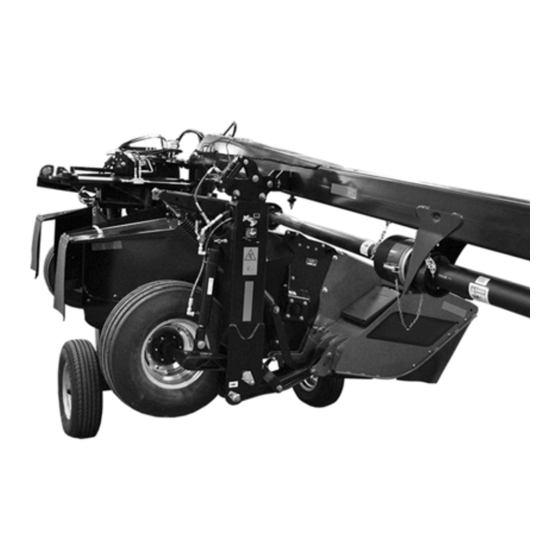
Rotary disc pull-type road-friendly transport
Hide thumbs
Also See for R113:
- Operator's manual (294 pages) ,
- Unloading and assembly instructions (234 pages) ,
- Assembly instruction manual (212 pages)

Subscribe to Our Youtube Channel
Related Manuals for MacDon R113


Summary of Contents for MacDon R113
- Page 1 R113/R116 Rotary Disc Pull-Type ™ Road-Friendly Transport (MD #C2002) Installation Instructions 214633 Revision C Original Instruction The harvesting specialists.
- Page 2 © 2019 MacDon Industries, Ltd. The information in this publication is based on the information available and in effect at the time of printing. MacDon Industries, Ltd. makes no representation or warranty of any kind, whether expressed or implied, with respect to the...
- Page 3 MacDon R113/R116 Rotary Disc Pull-Type to stay within width restrictions for most roads and highways while being towed. This document explains how to install the transport onto the R113/R116 Rotary Disc Pull-Type. A list of parts included in the kit is provided. Refer to...
- Page 4 List of Revisions At MacDon, we’re continuously making improvements, and occasionally these improvements affect product documentation.The following list provides an account of major changes from the previous version of this document. Section Summary of Change Internal Use Only Throughout Updated references to rotary disc pull-types according to Tech Pubs product naming conventions.
- Page 5 Section Summary of Change Internal Use Only • Added one electrical cap (MD #134742) for a total quantity of one. • Added one electrical harness (MD #281614) for a total quantity of one. 2.2 Transport Assembly Parts List – ECN 56030 Created a topic and parts list for the small parts bag ECN 57834 Small Parts Bag, page 8...
- Page 6 Section Summary of Change Internal Use Only 3.2.1 Installing Latch Assembly, page Added part numbers for clarity: Tech Pubs • MD #120333 • Step 13, page 15 • MD #18648 3.2.2 Installing Transport Assembly, Revised step. Hardware is now discarded. Tech Pubs page 16 •...
- Page 7 Section Summary of Change Internal Use Only Revised the step to read “rod end” (previously was 3.2.5 Installing Transport Swing Product Support “clevis end”). Added part numbers for clarity: Cylinder, page 22 Tech Pubs • MD # 281101 • Step 6, page 23 •...
- Page 8 Section Summary of Change Internal Use Only • Step 17, page 29 3.3.1 Installing Hydraulic Lines and Added part number MD #30753 for clarity. Tech Pubs Hoses, page 27 • Step 35, page 32 3.4.1 Installing Light Assemblies, page Added step and revised associated picture. Tech Pubs •...
- Page 9 Section Summary of Change Internal Use Only Added “washers” to the step and revised associated 3.4.6 Installing Slow Moving Vehicle ECN 57755 Sign, page 39 picture. • Step 5, page 39 3.4.6 Installing Slow Moving Vehicle Removed the last two steps of this procedure because Engineering Sign, page 39 the speed decal was already attached to the bracket.
-
Page 11: Table Of Contents
TABLE OF CONTENTS Introduction ..............................i List of Revisions............................ii Chapter 1: Safety ............................1 1.1 Signal Words ............................1 1.2 General Safety ............................2 Chapter 2: Parts List............................ 5 2.1 Transport Assembly Parts List ........................6 2.2 Transport Assembly Parts List – Small Parts Bag ...................8 2.3 Remote Control Parts List........................ - Page 12 TABLE OF CONTENTS 5.5 Converting from Transport to Field Mode – With Road-Friendly Transport ™ ........... 56 Chapter 6: Reference ..........................61 6.1 Attaching Rotary Disc Pull-Type to the Tractor ................... 61 6.1.1 Attaching with Drawbar Hitch ......................61 6.1.2 Attaching with Two-Point Hitch ...................... 68 ™...
-
Page 13: Chapter 1: Safety
Chapter 1: Safety 1.1 Signal Words Three signal words, DANGER, WARNING, and CAUTION, are used to alert you to hazardous situations. Two signal words, IMPORTANT and NOTE, identify non-safety related information. Signal words are selected using the following guidelines: DANGER Indicates an imminently hazardous situation that, if not avoided, will result in death or serious injury. -
Page 14: General Safety
SAFETY 1.2 General Safety CAUTION The following general farm safety precautions should be part of your operating procedure for all types of machinery. Protect yourself. • When assembling, operating, and servicing machinery, wear all protective clothing and personal safety devices that could be necessary for the job at hand. - Page 15 SAFETY • Wear close-fitting clothing and cover long hair. NEVER wear dangling items such as scarves or bracelets. • Keep all shields in place. NEVER alter or remove safety equipment. Make sure driveline guards can rotate independently of shaft and can telescope freely. •...
-
Page 17: Chapter 2: Parts List
Chapter 2: Parts List The following parts are included in this kit. 214633 Revision C... -
Page 18: Transport Assembly Parts List
2.1 Transport Assembly Parts List Figure 2.1: Transport Assembly Parts List 214633 Revision C... - Page 19 PARTS LIST Part Number Description ASSEMBLY – TRANSPORT WHEEL FRAME ASSEMBLY – PIN TRANSPORT ASSEMBLY – TRANSPORT VALVE MOUNTING 247958 BRACKET - SUPPORT ASSEMBLY – SUPPORT, DUAL LAMP, LH 223185 BRACKET – SMV, SIS SIGN 259218 ASSEMBLY – CYL, 3.5" TRANSPORT 136325 CAP - HYD SAE -6 ORFS ASSEMBLY –...
-
Page 20: Transport Assembly Parts List - Small Parts Bag
2.2 Transport Assembly Parts List – Small Parts Bag Figure 2.2: Transport Assembly – Small Parts Bag 214633 Revision C... - Page 21 PARTS LIST Part Number Description 30753 FASTENER - CABLE TIE BLACK 184301 CLAMP 135235 CLAMP - DOUBLE HOSE INSULATED 21763 FASTENER - CABLE TIE BLACK 281101 PIN - CLEVIS 18609 PIN - COTTER 1/4 DIA X 2 ZP 120333 PIN - CLEVIS, 18.95 MM, 127 MM 18648 PIN - COTTER 3/16 DIA X 1.25 ZP 136383...
-
Page 22: Remote Control Parts List
2.3 Remote Control Parts List The following parts are included in this kit. Figure 2.3: Parts List – Remote Control Parts 214633 Revision C... - Page 23 PARTS LIST Part Number Description ASSEMBLY - SWITCH BOX W DECAL, MD 281615 HARNESS - AUX PLUG 6. Not sold separately. 214633 Revision C...
-
Page 25: Chapter 3: Installation Instructions
Chapter 3: Installation Instructions This section describes the installation of the transport. The basic components are installed first, then hydraulic systems are connected, and the lighting and signage are installed last. Follow each procedure in order. IMPORTANT: Before installing the kit, lower the header to the ground and place the hitch in the mid (centered) position. 3.1 Moving Hitch Swing Cylinder When installing the transport you will need to move the hitch swing cylinder from the left side to the right side of the hitch. -
Page 26: Installing Components
INSTALLATION INSTRUCTIONS 3.2 Installing Components This section explains how to install the basic parts of the transport system. 3.2.1 Installing Latch Assembly 1. Disconnect right light electrical connection (A). 2. Remove two bolts (B) that secure right light assembly (C) to the carrier frame. - Page 27 INSTALLATION INSTRUCTIONS 11. Install latch assembly (A) onto the carrier frame as shown, and secure with the M20 bolts, washers, and nuts (B) retained in Step 10, page 14. Do NOT fully tighten bolts; adjustment of the latch assembly may be necessary. 12.
-
Page 28: Installing Transport Assembly
INSTALLATION INSTRUCTIONS 3.2.2 Installing Transport Assembly 1. Remove bolts (A), hardened washers, and nuts securing slow moving vehicle (SMV) sign (B) to the carrier frame. Remove the sign. Retain the sign for reinstallation. Discard the two bolts, washers, and nuts. Figure 3.8: SMV Sign Attached to Carrier Frame 2. - Page 29 INSTALLATION INSTRUCTIONS 6. Install two M20 x 65 bolts (A) (MD #136157), hardened washers (MD #112130), and nuts (MD #136122). 7. Temporarily install bolts (B) to help align the assembly. Figure 3.11: Pin Support 8. Rotate pin (A) until hole in pin aligns with holes in welded collar (B).
- Page 30 INSTALLATION INSTRUCTIONS 11. Retrieve cover assembly (B) from the shipping location. 12. Remove two bolts (A) from cover assembly (B). Retain the bolts and cover for installation later. Figure 3.14: Cover Assembly 13. Disconnect plugs P102 (A) and P301 (B) from the transport lighting module.
- Page 31 INSTALLATION INSTRUCTIONS 17. Attach module (A) to cover assembly bracket (B) using two M4 x 16 screws (C) (MD #136313) and M4 nuts (MD #030855). Torque hardware to 3 Nm (27 lbf·in). Figure 3.17: Lighting Module Attached to Bracket 18. Install cover support (B). 19.
-
Page 32: Installing Transport Wheels
INSTALLATION INSTRUCTIONS 3.2.3 Installing Transport Wheels 1. Cut the straps securing the transport assembly to the pallet. 2. Slowly lower the forklift until transport assembly wheel spindles (A) are approximately 305 mm (12 in.) off the ground. 3. Remove wheel bolts (B) from spindle hub (A) on the left side. -
Page 33: Installing Transport Valve
INSTALLATION INSTRUCTIONS Check tire pressure daily: • Maximum pressure is 310 kPa (45 psi) for field wheels (A). • Maximum pressure is 552 kPa (80 psi) for optional transport wheels (B). Figure 3.23: Field and Transport Wheels 3.2.4 Installing Transport Valve NOTE: Cover support bracket removed from illustrations for clarity. -
Page 34: Installing Transport Swing Cylinder
INSTALLATION INSTRUCTIONS 8. Remove nut (A) from support (D). 9. Install bolt (B) through support (D) and support (C), and then reinstall nut (A). Figure 3.26: Support Plate 3.2.5 Installing Transport Swing Cylinder 1. Remove the shipping bag from the pallet. 2. -
Page 35: Installing Transport Alignment Control
INSTALLATION INSTRUCTIONS 5. Install barrel end of transport swing cylinder (A) onto the carrier frame with clevis pin (B) (MD # 281101). Secure clevis pin with cotter pin (C) (MD #18609). Figure 3.29: Transport Swing Cylinder 6. Connect rod end (B) of transport swing cylinder (A) to transport casting. - Page 36 INSTALLATION INSTRUCTIONS 3. Secure cam assembly (A) onto hitch swing cylinder plate (B) with bolts and nuts (C). Torque nuts (C) to 55–60 Nm (40–45 lbf·ft). NOTE: When installing cam assembly (A), check for hose twisting. If required, loosen hose fitting to allow hose to untwist. Torque fitting when complete.
- Page 37 INSTALLATION INSTRUCTIONS 6. Ensure the end of cam arm (A) is parallel with clevis (B) on the rod end of the cylinder. If adjustment is required, use a bar to turn the clevis until the clevis is parallel with cam arm (A). NOTE: The rod end of the cylinder will be attached to the transport casting after the system is primed.
- Page 38 INSTALLATION INSTRUCTIONS 9. Retrieve paddle assembly (B) (MD #247625) from the shipping bag. 10. Install washers (A) (MD #184711) onto the bolts welded to the completion valve assembly. 11. Install paddle assembly (B) onto the welded bolts and secure with nuts (C) (MD #135799). NOTE: Make sure that paddle (B) is centered on the valve and moves freely.
-
Page 39: Installing Hydraulics
INSTALLATION INSTRUCTIONS 3.3 Installing Hydraulics This section explains how to install the transport hydraulic control system. 3.3.1 Installing Hydraulic Lines and Hoses NOTE: The cover support bracket has been removed from the illustrations for clarity. NOTE: Refer to the pull-type operator’s manual or technical manual for hydraulic fitting installation details. 1. - Page 40 INSTALLATION INSTRUCTIONS 6. Remove the cap from fitting (A). 7. Remove the plug from hose (B). Install hose to fitting (A) as shown. Figure 3.40: Alignment Valve Fitting 8. Install steel line (A) (MD #246954) from port A on the completion assembly to tee fitting (D).
- Page 41 INSTALLATION INSTRUCTIONS 13. Install hose (A) (MD #246366) from the outer port (rod end) on the transport cylinder block to tee fitting (D) in port D of the transport swing control. 14. Install hose (B) (MD #246366) from the inner port (base end) on the transport cylinder block to tee fitting (C) in port C of the transport swing control.
- Page 42 The secondary lift hose is required to lift the field wheels fully into storage position when the rotary disc pull-type is in transport mode. Retrieve the following secondary lift hose from the shipping bag: • R113: Use hose MD #224160. • R116: Use hose MD #224162. 18. Retrieve the blue collars with the number one (blue collar #1) on them (MD #136383) from the shipping bag.
- Page 43 INSTALLATION INSTRUCTIONS 25. Retrieve ORB-8 coupler (A) (MD #135563) and plastic cap (B) (MD #30340) from the hardware bag. 26. At the forward end of the hitch, install coupling (A) and plastic cap (B) onto secondary lift hose (C). Do NOT attach the hoses to the tractor at this time.
- Page 44 INSTALLATION INSTRUCTIONS 28. Route hose (A) (MD #247106) through opening (E) at the rear of the frame. 29. Feed shortest hose (A) through opening (B) in the carrier frame as shown with male end (C) at the hitch pivot. 30. Connect hose (A) (MD #247106) and hose (D) (MD #224160 or MD #224162) at the hitch pivot.
-
Page 45: Installing Electrical Components
INSTALLATION INSTRUCTIONS 3.4 Installing Electrical Components 3.4.1 Installing Light Assemblies 1. Disconnect the wiring harnesses at the left light assembly; there are two connectors per assembly. 2. Remove left light assembly (A). NOTE: The right light assembly was removed earlier. 3. -
Page 46: Installing Left Transport Harness
INSTALLATION INSTRUCTIONS 8. Install light assembly (A) onto the header left end with two M10 x 20 carriage bolts (B) (MD #136178) and lock nuts (MD #50101) from the shipping bag. Ensure the amber lamp faces the front of header and reflector faces outboard. -
Page 47: Connecting Right Transport Harness
11. Secure harness (A) with p-clips (MD #135235), existing bolts (C), and plastic clamp (D) (MD #184301) into existing holes. NOTE: R113: Harness for rotary disc pull-type is secured with one plastic clamp (D) (MD #184301). NOTE: R116: Harness for rotary disc pull-type is secured with two Figure 3.57: Harness Routing –... -
Page 48: Connecting Selector Valve And Transport Lighting Module
INSTALLATION INSTRUCTIONS 3.4.4 Connecting Selector Valve and Transport Lighting Module 1. Remove valve connector plug (A). Figure 3.59: Connector Plug 2. Locate plugs P102 (A) and P502 (B) on the transport harness at the header end of the hitch. Route plugs P102 (A) and P502 (B) towards selector valve (C). - Page 49 INSTALLATION INSTRUCTIONS 3. Locate connector (C) that branches off seven-pole transport plug (A) and attach it to remote wiring harness (B). Figure 3.62: Transport Harness 4. If your tractor has a three-pin auxiliary power connection: NOTE: The remote control has internal protection which prevents damage caused by incorrect wiring, short circuits, or overload conditions.
- Page 50 INSTALLATION INSTRUCTIONS 5. If your tractor does NOT have a three-pin auxiliary power connection: NOTE: The remote control has internal protection which prevents damage caused by incorrect wiring, short circuits, or overload conditions. Connect remote control wires (A) to the tractor’s power supply: •...
-
Page 51: Installing Slow Moving Vehicle Sign
INSTALLATION INSTRUCTIONS 3.4.6 Installing Slow Moving Vehicle Sign 1. Retrieve the slow moving vehicle (SMV) sign that was previously removed. 2. Remove bolts (A), and discard existing bracket (B). Retain the two bolts, nuts, and washers. NOTE: For model year 2019 and prior: Pull-types are NOT equipped with washers. -
Page 52: Installing Cover
INSTALLATION INSTRUCTIONS 3.5 Installing Cover 1. Install cover (A) onto the cover support. 2. Install bolts (B). Torque to 55–65 Nm (41–48 lbf·ft). Figure 3.69: Cover 214633 Revision C... -
Page 53: Connecting Hydraulics
INSTALLATION INSTRUCTIONS 3.6 Connecting Hydraulics WARNING Do NOT use remote hydraulic system pressures over 20,684 kPa (3000 psi). Check your tractor operator’s manual for remote system pressure. NOTE: Refer to the numbered/colored bands on the hoses to identify lift, swing/transport, and tilt hose sets. Table 3.1 Hydraulic System Hoses Tractor System... -
Page 54: Priming The Hitch Swing Cylinder
INSTALLATION INSTRUCTIONS 3.7 Priming the Hitch Swing Cylinder NOTE: The hitch swing cylinder must be primed before it is connected to the rear arm link. 1. Move the transport switch on the remote control to lower position (B) and ensure that light (A) is illuminated. The hitch swing circuit will now be active. - Page 55 INSTALLATION INSTRUCTIONS NOTE: Ensure there is no contact with the rear link arm when the hitch swing cylinder extends. 2. With the cylinder disconnected from the rear arm link, using the tractor’s hydraulics, extend and retract swing cylinder (A) several times to purge any air in the cylinder. Figure 3.72: Hydraulic System 3.
-
Page 57: Chapter 4: Checking And Adjusting The Cam On The Transport Deploy / Swing Mechanism
Chapter 4: Checking and Adjusting the Cam on the Transport Deploy / Swing Mechanism Cam angle (A) on the transport deploy/swing mechanism assembly is factory-set to 112°. It may be necessary to adjust the cam angle if the transport does NOT properly deploy. When the system is functioning properly, the header should start to rotate as the transport wheels reach the end of their travel (beneath the header). -
Page 59: Chapter 5: Transporting The Rotary Disc Pull-Type
Chapter 5: Transporting the Rotary Disc Pull-Type You can transport the rotary disc pull-type using a tractor in either field mode or transport mode. • To prepare a rotary disc pull-type for towing with a tractor in field mode without using the Road-Friendly Transport ™... - Page 60 TRANSPORTING THE ROTARY DISC PULL-TYPE 3. Connect the hitch swing cylinder hoses (collars with #2) to tractor’s hydraulic circuit (A). For instructions, refer to Connecting Hydraulics, page Figure 5.1: Hydraulic Connection 4. Raise the rotary disc pull-type fully and close the lift cylinder lock-out valve by turning handle (A) to the closed position (90°...
-
Page 61: Transporting With A Tractor
TRANSPORTING THE ROTARY DISC PULL-TYPE 5.2 Transporting with a Tractor ™ If towing endwise with the optional Road-Friendly Transport system, refer to 5.4 Converting from Field to Transport Mode – With Road-Friendly Transport ™ , page 1. Before transporting the rotary disc pull-type with a tractor, ensure the machine is prepared for transport. Refer to Preparing Rotary Disc Pull-Type for Transport, page 47 for instructions. -
Page 62: Transport Lighting
TRANSPORTING THE ROTARY DISC PULL-TYPE 5.3 Transport Lighting 5.3.1 Lighting – With Road-Friendly Transport ™ ™ Option The rotary disc pull-type is equipped with two bidirectional amber lights (A) that function as flashing hazard lights and turn signals. Red lights (B) located on the inboard side of the amber lights function as both tail and brake lights. -
Page 63: Converting From Field To Transport Mode - With Road-Friendly Transport
TRANSPORTING THE ROTARY DISC PULL-TYPE 5.4 Converting from Field to Transport Mode – With Road-Friendly ™ ™ Transport DANGER To prevent serious injury or death, do NOT convert the machine into, or from transport mode until all people, animals, and objects are clear of the unit’s rotational range. DANGER Stop the power take-off (PTO) before converting the unit into transport mode. - Page 64 TRANSPORTING THE ROTARY DISC PULL-TYPE 3. While the light is illuminated, raise the rotary disc pull- type fully by extending the field wheel cylinders. Figure 5.7: Raising Rotary Disc Pull-Type 4. Operate the hitch swing control lever to rotate the rotary disc pull-type to the right until the cam bearing nut is aligned with the green section of the transport alignment gauge decal.
- Page 65 TRANSPORTING THE ROTARY DISC PULL-TYPE 6. Operate the hitch swing control lever to lower transport wheels (A) and hold the lever until the rotary disc pull-type is lifted off the ground. 7. Continue to hold the hitch swing control lever so that rotary disc pull-type (B) rotates to the left and under the hitch.
- Page 66 TRANSPORTING THE ROTARY DISC PULL-TYPE Steering lock-out: Close the valve by turning handle (A) to the closed position (90° to the hose). Figure 5.13: Steering Lock-Out Valve Lift cylinder lock-out: Close the valve by turning handle (A) to the closed position (90° to the hose). Repeat on opposite side.
- Page 67 TRANSPORTING THE ROTARY DISC PULL-TYPE 13. Once field-to-transport conversion (A) is complete, leave the switch in upper position (C). Ensure that light (B) is NOT illuminated. Figure 5.16: Control Box 214633 Revision C...
-
Page 68: Converting From Transport To Field Mode - With Road-Friendly Transport
TRANSPORTING THE ROTARY DISC PULL-TYPE 5.5 Converting from Transport to Field Mode – With Road-Friendly ™ ™ Transport DANGER To prevent serious injury or death, do NOT convert the machine into, or from transport mode until all people, animals, and objects are clear of the unit’s rotational range. CAUTION To prevent equipment damage, ensure cutterbar doors are properly closed before converting the machine from field to transport mode. - Page 69 TRANSPORTING THE ROTARY DISC PULL-TYPE Steering lock-out: Open the valve by turning handle (A) to the open position (in line with the hose). Figure 5.19: Steering Lock-Out Valve Lift cylinder lock-out: Open the valve by turning handle (A) to the open position (in line with the hose). Repeat on opposite side.
- Page 70 TRANSPORTING THE ROTARY DISC PULL-TYPE 5. Operate the hitch swing control lever to rotate the rotary disc pull-type to the right. The rotary disc pull-type will stop when it reaches operating position. NOTE: A sequenced movement transitions the rotary disc pull-type from transport to field mode.
- Page 71 TRANSPORTING THE ROTARY DISC PULL-TYPE 8. Once transport-to-field conversion (A) is complete, leave the switch in lower position (C). Ensure that light (B) is illuminated. Figure 5.24: Control Box 214633 Revision C...
-
Page 73: Chapter 6: Reference
Chapter 6: Reference 6.1 Attaching Rotary Disc Pull-Type to the Tractor Refer to the attachment procedure that applies to your tractor: • 6.1.1 Attaching with Drawbar Hitch, page 61 • 6.1.2 Attaching with Two-Point Hitch, page 68 6.1.1 Attaching with Drawbar Hitch WARNING To avoid bodily injury or death from the unexpected startup of the machine, always stop the engine and remove the key before making adjustments to the machine. - Page 74 REFERENCE 1. Remove lynch pin (A) from clevis pin (B), and remove the clevis pin from the rotary disc pull-type hitch. Figure 6.1: Rotary Disc Pull-Type Hitch – Model Year 2018 and Prior Figure 6.2: Rotary Disc Pull-Type Hitch – Model Year 2019 Figure 6.3: Rotary Disc Pull-Type Hitch –...
- Page 75 REFERENCE 2. Move the tractor to position drawbar hitch adapter (A) under pin (B) in the hitch. Adjust height as necessary with jack. 3. Shut down the engine, and remove the key from the ignition. Figure 6.4: Rotary Disc Pull-Type Hitch Figure 6.5: Rotary Disc Pull-Type Hitch Figure 6.6: Rotary Disc Pull-Type Hitch –...
- Page 76 REFERENCE 4. Lower the hitch with the jack so that pin (A) engages drawbar hitch adapter (B). 5. Install clevis pin (C) and secure with lynch pin (D). Figure 6.7: Rotary Disc Pull-Type Hitch – Model Year 2018 and Prior Figure 6.8: Rotary Disc Pull-Type Hitch –...
- Page 77 REFERENCE 6. Position primary driveline (A) onto the tractor power take- off (PTO). 7. Pull back collar (B) on driveline (A), and push the driveline until it locks. Release collar. 8. Route safety chain (C) from the rotary disc pull-type through chain support (D) on the drawbar hitch adapter and around the tractor drawbar support.
- Page 78 REFERENCE 9. Raise jack (A), and remove pin (B). Figure 6.13: Hitch Jack – Model Year 2018 and Prior Figure 6.14: Hitch Jack – Model Year 2019 Figure 6.15: Hitch Jack – Model Year 2020 and Later 214633 Revision C...
- Page 79 REFERENCE 10. Move jack (A) to storage position on top of hitch, and secure with pin (B). 11. Proceed to 3.6 Connecting Hydraulics, page Figure 6.16: Drawbar Jack Storage – Model Year 2018 and Prior Figure 6.17: Drawbar Jack Storage – Model Year 2019 Figure 6.18: Drawbar Jack Storage –...
-
Page 80: Attaching With Two-Point Hitch
REFERENCE 6.1.2 Attaching with Two-Point Hitch Follow these steps to attach category II, IIIN, and III two-point hitches: WARNING To avoid bodily injury or death from the unexpected startup of the machine, always stop the engine and remove the key before making adjustments to the machine. 1. - Page 81 REFERENCE 6. Check distance (C) between tractor primary power take-off (PTO) shaft (A) and rotary disc pull-type hitch gearbox shaft (B) without the front half of the driveline attached. 7. Ensure that distance measurement (C) does NOT exceed the dimensions listed in Table 6.1, page Table 6.1 Distance between Hitch Gearbox and Tractor PTO Driveline Shaft Size...
- Page 82 REFERENCE For model year 2019 and prior: CAUTION Check to be sure all bystanders have cleared the area. 10. Clear bystanders from the area and start tractor. Do NOT operate the rotary disc pull-type. 11. Start the tractor and raise the hitch so that stand (A) is off the ground.
- Page 83 REFERENCE For model year 2020 and later: CAUTION Check to be sure all bystanders have cleared the area. 16. Clear bystanders from the area and start the tractor. Do NOT operate the pull-type. 17. Raise the hitch so that stand (A) is off the ground. 18.
-
Page 84: Converting Road-Friendly Transport Decal
REFERENCE ™ ™ 6.2 Converting Road-Friendly Transport Decal A - Converting From Field to Transport B - Converting From Transport to Field 214633 Revision C... - Page 86 MacDon Industries Ltd. MacDon Brasil Agribusiness Ltda. 680 Moray Street Rua Grã Nicco, 113, sala 404, B. 04 Winnipeg, Manitoba Mossunguê, Curitiba, Paraná Canada R3J 3S3 CEP 81200-200 Brasil t. (204) 885-5590 f. (204) 832-7749 t. +55 (41) 2101-1713 f. +55 (41) 2101-1699 MacDon, Inc.
Need help?
Do you have a question about the R113 and is the answer not in the manual?
Questions and answers