
Subscribe to Our Youtube Channel
Related Manuals for WAGO Compact Controller 100


Summary of Contents for WAGO Compact Controller 100
- Page 1 Manual WAGO I/O System Compact 751-9301 Compact Controller 100 Version 1.1.0, valid from FW Version 03.08.07(20)
- Page 2 We wish to point out that the software and hardware terms as well as the trademarks of companies used and/or mentioned in the present manual are generally protected by trademark or patent. WAGO is a registered trademark of WAGO Verwaltungsgesellschaft mbH. Manual Version 1.1.0, valid from FW Version 03.08.07(20)
-
Page 3: Table Of Contents
WAGO I/O System Compact Table of Contents 751-9301 Compact Controller 100 Table of Contents Notes about this Documentation .............. 8 Validity of this Documentation ..............8 Copyright....................8 Property rights..................9 Symbols ....................11 Number Notation ..................13 Font Conventions ................... 13 Important Notes .................. - Page 4 Table of Contents WAGO I/O System Compact 751-9301 Compact Controller 100 4.3.1 Mechanical Data................37 4.3.2 System Data ..................37 4.3.3 Power Supply ..................37 4.3.4 Clock ....................38 4.3.5 Programming ..................38 4.3.6 ETHERNET ..................38 4.3.7 Communication Interface ..............39 4.3.8...
- Page 5 Setting an IP Address ................79 8.3.1 IP Connection via USB ..............80 8.3.2 Changing an IP Address using “WAGO Ethernet Settings” ....81 8.3.3 Temporarily Setting a Fixed IP Address ..........83 8.3.4 Setting the IP Address via the WBM ..........84 8.3.5...
- Page 6 “Device Status” Page ............. 124 15.1.1.1.2 “Vendor Information” Page ............. 126 15.1.1.1.3 “PLC Runtime Information” Page ........... 127 15.1.1.1.4 “WAGO Software License Agreement” Page ......129 15.1.1.1.5 “Open Source Licenses” Page ..........130 15.1.1.1.6 “WBM Third Party License Information” Page ....... 131 15.1.1.1.7 “WBM Version”...
- Page 7 WAGO I/O System Compact Table of Contents 751-9301 Compact Controller 100 15.1.1.2 “Configuration” Tab ..............133 15.1.1.2.1 “PLC Runtime Configuration” Page ........133 15.1.1.2.2 “TCP/IP Configuration” Page ..........136 15.1.1.2.3 “Ethernet Configuration” Page ..........138 15.1.1.2.4 “Configuration of Host and Domain Name” Page ....141 15.1.1.2.5...
-
Page 8: Notes About This Documentation
In addition, ensure that any supplement to this documentation is included, if necessary. Validity of this Documentation This documentation is only applicable to the “Compact Controller 100” controller (751-9301). Copyright This Manual, including all figures and illustrations, is copyright-protected. Any further use of this Manual by third parties that violate pertinent copyright provisions is prohibited. -
Page 9: Property Rights
WAGO I/O System Compact Notes about this Documentation 751-9301 Compact Controller 100 Property rights Third-party trademarks are used in this documentation. This section contains the trademarks used. The “®” and “TM” symbols are omitted hereinafter. • Adobe and Acrobat are registered trademarks of Adobe Systems Inc. - Page 10 Notes about this Documentation WAGO I/O System Compact 751-9301 Compact Controller 100 • PROFIBUS is a registered trademark of the PROFIBUS ® Nutzerorganisation e.V. (PNO). • PROFINET is a registered trademark of the PROFIBUS ® Nutzerorganisation e.V. (PNO). • QR Code is a registered trademark of DENSO WAVE INCORPORATED.
-
Page 11: Symbols
WAGO I/O System Compact Notes about this Documentation 751-9301 Compact Controller 100 Symbols Personal Injury! Indicates a high-risk, imminently hazardous situation which, if not avoided, will result in death or serious injury. Personal Injury Caused by Electric Current! Indicates a high-risk, imminently hazardous situation which, if not avoided, will result in death or serious injury. - Page 12 Notes about this Documentation WAGO I/O System Compact 751-9301 Compact Controller 100 Additional Information: Refers to additional information which is not an integral part of this documentation (e.g., the Internet). Manual Version 1.1.0, valid from FW Version 03.08.07(20)
-
Page 13: Number Notation
WAGO I/O System Compact Notes about this Documentation 751-9301 Compact Controller 100 Number Notation Table 1: Number Notation Number Code Example Note Decimal Normal notation Hexadecimal 0x64 C notation Binary '100' In quotation marks, nibble separated '0110.0100' with dots (.) -
Page 14: Important Notes
2.1.1 Subject to Changes WAGO GmbH & Co. KG reserves the right to provide for any alterations or modifications. WAGO GmbH & Co. KG owns all rights arising from the granting of patents or from the legal protection of utility patents. Third-party products are always mentioned without any reference to patent rights. -
Page 15: Technical Condition Of Specified Devices
These modules contain no parts that can be serviced or repaired by the user. The following actions will result in the exclusion of liability on the part of WAGO GmbH & Co. KG: •... -
Page 16: Safety Advice (Precautions)
Important Notes WAGO I/O System Compact 751-9301 Compact Controller 100 Safety Advice (Precautions) For installing and operating purposes of the relevant device to your system the following safety precautions shall be observed: Do not work on devices while energized! All power sources to the device shall be switched off prior to performing any installation, repair or maintenance work. - Page 17 WAGO I/O System Compact Important Notes 751-9301 Compact Controller 100 Power from SELV/PELV power supply only! All field signals and field supplies connected to the controller „Compact Controller 100“ (751-9301) must be powered from SELV/PELV power supply(s)! Ensure proper contact with the DIN-rail! Proper electrical contact between the DIN-rail and device is necessary to maintain the EMC characteristics and function of the device.
- Page 18 Important Notes WAGO I/O System Compact 751-9301 Compact Controller 100 Avoid electrostatic discharge! The devices are equipped with electronic components that may be destroyed by electrostatic discharge when touched. Please observe the safety precautions against electrostatic discharge per DIN EN 61340-5-1/-3. When handling the devices, please ensure that environmental factors (personnel, work space and packaging) are properly grounded.
-
Page 19: Licensing Terms Of The Software Package Used
They can be accessed via the WBM page “Legal Information” > “Open Source Software.” You can obtain the source code with licensing terms of the open-source software from WAGO GmbH & Co. KG on request. Send your request to support@wago.com with the subject “Controller Board Support Package.”... -
Page 20: Special Use Conditions For Ethernet Devices
Please note the following when using ETHERNET devices in your system: • Do not connect control components and control networks directly to an open network such as the Internet or an office network. WAGO recommends putting control components and control networks behind a firewall. •... -
Page 21: Overview
751-9301 Compact Controller 100 Overview The controller 751-9301(Compact Controller 100) is an automation device that can perform control tasks of a PLC. It is suitable for mounting on a DIN rail and stands out on account of its various interfaces. Among other things, the controller has integrated digital and analog inputs and outputs and a serial onboard interface in accordance with EIA-485/RS-485. - Page 22 </dg_ Only use recommended memory card! Use only the SD memory card available from WAGO (item No. 758-879/000- 001) as it is suitable for industrial applications subjected to environmental extremes and for use in this device. Compatibility with other commercially available storage media cannot be guaranteed.
-
Page 23: Properties
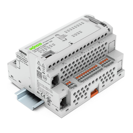
WAGO I/O System Compact Properties 751-9301 Compact Controller 100 Properties Hardware Description 4.1.1 View Figure 1: View Manual Version 1.1.0, valid from FW Version 03.08.07(20) -
Page 24: Table 3: Legend For Figure "View
Properties WAGO I/O System Compact 751-9301 Compact Controller 100 Table 3: Legend for figure “View” Position Description See sector Slot for memory card ”Memory Card Slot” LED indicators – Status DI/DO “Display Elements” > „Status DI/DO LEDs“ Operating Mode Switch “Operating Elements”... -
Page 25: Labeling And Type Plate
WAGO I/O System Compact Properties 751-9301 Compact Controller 100 4.1.2 Labeling and type plate The labeling and the type plate are attached to the left side of the product. The following information is included in it: Table 4: Labeling and type plate... - Page 26 Properties WAGO I/O System Compact 751-9301 Compact Controller 100 Figure 1: Type plate (Example) Manual Version 1.1.0, valid from FW Version 03.08.07(20)
-
Page 27: Connectors
Not assigned Not assigned 4.1.3.2 Service Interface The service interface „X3“ is used for the communication with WAGO Ethernet Settings. The USB service interface is designed as a USB-C socket. The interface supports USB Specification 2.0. The controller appears on the host device (PC) as a peripheral device in device mode. -
Page 28: Digital Outputs
Properties WAGO I/O System Compact 751-9301 Compact Controller 100 The inputs provide high-side switching. If the 24V potential for field power Uout+ (“X12” connector) is switched to an input connection, the signal status for the corresponding input channel is set to “high”. -
Page 29: Analog Inputs And Outputs
WAGO I/O System Compact Properties 751-9301 Compact Controller 100 Table 8: Digital outputs – “X5” Contact Signal Description Supply voltage input (DO1 … DO4) Ground Digital output 1 Ground Digital output 2 Ground Digital output 3 Ground Digital output 4 Ground 4.1.3.5... -
Page 30: Analog Outputs
Properties WAGO I/O System Compact 751-9301 Compact Controller 100 4.1.3.5.2 Analog outputs The controller generates signals with standardized values of 0 …+10 V for the field range. The product has 2 output channels, making two 2-wire actuators possible. The actuators are connected via the AO1 and ground connections or AO2 and ground. -
Page 31: Operating As An Rs-485 Interface
Compact Controller 100 with a bus terminating resistor (120 Ohm). A bias network (pull-up and pull-down resistor) is also integrated in the Compact Controller 100 to keep the bus lines at a defined level when no other subscriber is active. -
Page 32: Analog Temperature Sensors
Properties WAGO I/O System Compact 751-9301 Compact Controller 100 4.1.3.7 Analog Temperature Sensors The connections are used to connect actuators and sensors. picoMAX® plugs with Push-in CAGE CLAMP® Connections are used. Analog temperature sensors such as Pt1000 or Ni1000 can be connected to the controller. -
Page 33: Display Elements
Designation Color Description Red/Green/Off System Status Red/Green/Off PLC program status Red/Green/Off User LED, programmable using function blocks from the WAGO libraries to control the LEDs 4.1.4.2 Network Connection LED Table 14: “LNK ACT” LEDs Designation Color Description LNK ACT1 Green/Off... -
Page 34: Operating Elements
Properties WAGO I/O System Compact 751-9301 Compact Controller 100 4.1.5 Operating Elements 4.1.5.1 Operating Mode Switch </dg_ Table 17: Mode Selector Switch Position Actuation Function Normal operation Latching e!RUNTIME applications running. Stop STOP Latching All e!RUNTIME applications have stopped. Reset warm start or... -
Page 35: Memory Card Slot
</dg_ Only use recommended memory card! Use only the SD memory card available from WAGO (item No. 758-879/000- 001) as it is suitable for industrial applications subjected to environmental extremes and for use in this device. Compatibility with other commercially available storage media cannot be guaranteed. -
Page 36: Schematic Diagram
Properties WAGO I/O System Compact 751-9301 Compact Controller 100 Schematic Diagram Figure 3: Schematic diagram Manual Version 1.1.0, valid from FW Version 03.08.07(20) -
Page 37: Technical Data
Push-push mechanism, sealable cover lid Type of memory card MicroSD up to 32 Gbytes (All guaranteed properties are valid only in connection with the WAGO memory cards 758-879/000-3102 and 758-879/000-3108.) 4.3.3 Power Supply Table 20: Technical Data – Power Supply Input Voltage System U 24 VDC (SELV, −15 …... -
Page 38: Clock
Properties WAGO I/O System Compact 751-9301 Compact Controller 100 Buffer for system power supply! The system power supply and, if necessary, the field supply must be buffered to bridge power outages. As the power demand depends on the respective node configuration, buffering is not implemented internally. -
Page 39: Communication Interface
WAGO I/O System Compact Properties 751-9301 Compact Controller 100 4.3.7 Communication Interface Table 24: Technical Data – Communication Interface Interface 1 x serial interface per TIA/EIA 485, picoMAX ® Protocols depending on IEC program Transmission channels 1 TxD / 1 RxD, half duplex... -
Page 40: Digital Outputs
Properties WAGO I/O System Compact 751-9301 Compact Controller 100 4.3.10 Digital outputs Table 27: Technical Data – Digital Outputs Number of digital outputs Output voltage 24 VDC Load types DC, general use (according to UL 61010-2-201, paragraph 4.4.2.101) Reverse voltage protection Switching frequency (max.) -
Page 41: Climatic Environmental Conditions
WAGO I/O System Compact Properties 751-9301 Compact Controller 100 4.3.13 Climatic Environmental Conditions Table 30: Technical Data – Climatic Environmental Conditions Surrounding air temperature (operation) −25 … +60 °C Surrounding air temperature (storage) −25 … +85 °C Relative humidity (without 5 …... -
Page 42: Analog Temperature Sensors
Properties WAGO I/O System Compact 751-9301 Compact Controller 100 4.3.14 Analog Temperature Sensors Table 31: Technical Data – Analog Temperature Sensors Number of inputs Sensor types Switchable: Pt1000, Ni1000 or raw value Temperature range Pt –60 … +350 °C Ni –60 … +350 °C Measuring current (typ.) -
Page 43: Approvals
WAGO I/O System Compact Properties 751-9301 Compact Controller 100 Approvals The following approvals have been granted to the “Compact Controller 100” controller (751-9301): Conformity Marking UK Conformity Assessed Ordinary UL61010-2-201 (in preparation) Locations Manual Version 1.1.0, valid from FW Version 03.08.07(20) -
Page 44: Function Description
Function Description WAGO I/O System Compact 751-9301 Compact Controller 100 Function Description </dg_ Network 5.1.1 Interface Configuration The X1 and X2 network interfaces of the controller are connected with an integrated configurable 3-port switch, in which the third port is connected to the CPU. - Page 45 WAGO I/O System Compact Function Description 751-9301 Compact Controller 100 When switching to operating with separate interfaces, interface X2 is initialized with the setting values last valid for it. The connections on the X1 interface persist. When operating with separate interfaces and fixed IP address, the device can still be accessed via the interface X2 via the regular IP address.
-
Page 46: Mac Id And Ip Address Assignment Examples
Function Description WAGO I/O System Compact 751-9301 Compact Controller 100 5.1.1.3 MAC ID and IP Address Assignment Examples One common network with one common IP address for both ports Figure 5: One Bridge with Two Ports Table 34: MAC ID and IP Address Assignment for One Bridge with Two Ports... -
Page 47: Network Security
WAGO I/O System Compact Function Description 751-9301 Compact Controller 100 5.1.2 Network Security 5.1.2.1 Users and Passwords Several groups of users are provided in the controller which can be used for various services. Default passwords are set for all users. We strongly recommend changing these... -
Page 48: Wbm User Group
Function Description WAGO I/O System Compact 751-9301 Compact Controller 100 5.1.2.1.2 WBM User Group WBM has its own user administration system. The users in this system are isolated from the other user groups in the system for security reasons. Detailed information about this is given in the Section “WBM User Administration”. -
Page 49: Snmp User Group
WAGO I/O System Compact Function Description 751-9301 Compact Controller 100 5.1.2.1.4 SNMP User Group The SNMP service manages its own users. In its initial state, no users are stored in the system. Manual Version 1.1.0, valid from FW Version 03.08.07(20) -
Page 50: Web Protocols For Wbm Access
Function Description WAGO I/O System Compact 751-9301 Compact Controller 100 5.1.2.2 Web Protocols for WBM Access The HTTP and HTTPS web protocols can be used to access the WBM pages for the controller. HTTPS is preferred because it uses the SSL/TLS protocol. The... - Page 51 WAGO I/O System Compact Function Description 751-9301 Compact Controller 100 BSI Guidelines on Migration to TLS 1.2 The German Federal Office for Information Security guidelines on migration to TLS 1.2 contain “compatibility matrices” that show what software is comparable with TLS 1.2.
-
Page 52: Root Certificates
Function Description WAGO I/O System Compact 751-9301 Compact Controller 100 5.1.2.3 Root Certificates For communication encrypted with TLS, root certificates are used to verify the authenticity of the communication partner. A root certificate, which is signed by a certificate authority, serves to verify the validity of all certificates issued by this certificate authority. -
Page 53: Network Configuration
WAGO I/O System Compact Function Description 751-9301 Compact Controller 100 </dg_ 5.1.3 Network Configuration 5.1.3.1 Host Name/Domain Name Without a host name configuration, the controller is assigned a default name which includes the last three values of the controller's MAC address. This name... - Page 54 Function Description WAGO I/O System Compact 751-9301 Compact Controller 100 no specific routing entry exists for their destination address and destination mask are sent to this default gateway. Default Gateway: If the value “default” is entered in the “Destination Address” field, a default gateway, also called a default route, is defined.
- Page 55 WAGO I/O System Compact Function Description 751-9301 Compact Controller 100 For forwarding network communication through a router, it is necessary to note that corresponding routing entries must be provided not only for the router, but also for the respective endpoints of the communication. The routing entries of the endpoints must ensure that the desired network data packets are sent via the router, both when the connection is established and with the replies.
-
Page 56: Network Services
Function Description WAGO I/O System Compact 751-9301 Compact Controller 100 5.1.4 Network Services 5.1.4.1 DHCP Client The controller can get network parameters from an external DHCP master via the DHCP Client service. The following parameters can be obtained: • IP address •... -
Page 57: Table 38: List Of Parameters Transmitted Via Dhcp
WAGO I/O System Compact Function Description 751-9301 Compact Controller 100 The settings are made, for example, in the WBM via the “DHCP Configuration” page. The DHCP server also passes other parameters in addition to the IP address. The following table shows the complete list. -
Page 58: Dns Server
Function Description WAGO I/O System Compact 751-9301 Compact Controller 100 server must be manually configured. For the controller, the DHCP server service is handled by the program "dnsmasq". From a Linux command line, an editor must be used to change the file ®... -
Page 59: Cloud Connectivity Functionality
WAGO I/O System Compact Function Description 751-9301 Compact Controller 100 5.1.5 Cloud Connectivity Functionality With the cloud connectivity functionality and an IEC library, the controller is available as a gateway for Internet-of-Things (IoT) applications. This means the controller can collect the data from all the connected devices, access the Internet via the built-in Ethernet interface or the mobile communications module and send the data to the cloud. -
Page 60: Components Of The Cloud Connectivity Software Package
Observe the necessary data protection and security settings! Before using the cloud connectivity functionality, consult the corresponding handbook and familiarize yourself with data protection and security issues. You will find this in the Downloads area at www.wago.com. 5.1.5.1 Components of the Cloud Connectivity Software Package... -
Page 61: Memory Card Function
Memory Card Function </dg_ Only use recommended memory card! Use only the SD memory card available from WAGO (item No. 758-879/000- 001) as it is suitable for industrial applications subjected to environmental extremes and for use in this device. Compatibility with other commercially available storage media cannot be guaranteed. -
Page 62: Data Backup
Function Description WAGO I/O System Compact 751-9301 Compact Controller 100 5.2.2 Data Backup The controller has a backup function and a restore function. The necessary settings can be made and the functions can be executed via the WBM pages “Backup” and “Restore” menus. -
Page 63: Restore Function
WAGO I/O System Compact Function Description 751-9301 Compact Controller 100 Only one package may be copied to the network! If you have specified “Network” as the storage location, only one package may be selected for each storing process. No backup of the memory card! Backup from the memory card to the internal flash memory is not possible. - Page 64 Function Description WAGO I/O System Compact 751-9301 Compact Controller 100 File size must not exceed the size of the internal drive! Note that the amount of data in the media/sd/copy/ directory must not exceed the total size of the internal drive.
-
Page 65: Inserting A Memory Card During Operation
WAGO I/O System Compact Function Description 751-9301 Compact Controller 100 5.2.3 Inserting a Memory Card during Operation The fieldbus nodes and the PLC program are running. Insert a memory card during ongoing operation. During normal operation, the memory card is incorporated into the file system of the controller as a drive. -
Page 66: Setting The Home Directory For The Runtime System
Function Description WAGO I/O System Compact 751-9301 Compact Controller 100 5.2.5 Setting the Home Directory for the Runtime System The home directory for the runtime system is located in the controller's internal memory by default. An existing boot project may be saved in the home directory. -
Page 67: Table 40: Loading A Boot Project
WAGO I/O System Compact Function Description 751-9301 Compact Controller 100 Table 40: Loading a Boot Project “Home Boot Project Memory Card Directory on Stored in with Boot Boot Project is Memory Card Internal Flash Project Loaded ... Enabled” Memory Inserted... -
Page 68: Mounting
Mounting WAGO I/O System Compact 751-9301 Compact Controller 100 Mounting Installation Position The following installation positions are permitted: Table 41: Installation positions and permitted ambient temperatures Figure Installation position Permitted ambient temperature Horizontal –25 … +60 °C Vertical –25 … +55 °C Bottom –25 …... -
Page 69: Mounting Onto Carrier Rail
I/O system. If other carrier rails are used, then a technical inspection and approval of the rail by WAGO GmbH & Co. KG should take place. Carrier rails have different mechanical and electrical properties. For the optimal system setup on a carrier rail, certain guidelines must be observed: •... -
Page 70: Wago Din Rails
Mounting WAGO I/O System Compact 751-9301 Compact Controller 100 6.2.2 WAGO DIN Rails WAGO carrier rails meet the electrical and mechanical requirements shown in the table below. Table 42: WAGO DIN Rails Item No. Description 210-112 35 × 7.5; 1 mm; steel; bluish, tinned, chromed; slotted 210-113 35 ×... - Page 71 WAGO I/O System Compact Mounting 751-9301 Compact Controller 100 The spacing creates room for heat transfer, installation or wiring. The spacing to cable conduits also prevents conducted electromagnetic interferences from influencing the operation. If the installation space in the control cabinet or small installation distribution boards is limited, use angled network cables or patch cables for the X1 and X2 network connections, if necessary.
-
Page 72: Inserting Devices
(pluggable). Additional information on picoMAX is available in the catalog “picoMAX ‒ The ® ® Pluggable Connection System” or online at www.wago.com. 6.4.2.1 Status at delivery When delivered, the female connectors are not plugged into the device, but included. Manual... -
Page 73: Removing The Female Connector
WAGO I/O System Compact Mounting 751-9301 Compact Controller 100 6.4.2.2 Removing the Female Connector WAGO recommends using a picoMAX unlocking tool (referred to in the following ® text as the “unlocking tool”). Further information on the unlocking tool is provided in the Section “Accessories”... -
Page 74: Removing The Female Connector With Wiring
751-9301 Compact Controller 100 If you do not have an unlocking tool available, you can also remove the female connector with a WAGO operating tool or a screwdriver Do not insert the tool in the ventilation slots! Components inside the device may be damaged if the blade of an operating tool enters the ventilation slots. -
Page 75: Plugging In The Female Connector
WAGO I/O System Compact Mounting 751-9301 Compact Controller 100 Do not pull on the cables when using a screwdriver or operating tool! When using a screwdriver or operating tool to remove the female connector do not pull on the cables! Grip underneath the protruding rim of the female connector to pull it out. -
Page 76: Connecting
Connecting WAGO I/O System Compact 751-9301 Compact Controller 100 Connecting Earthing The controller is grounded by the spring contacts on the underside of the product by snapping it onto the grounded DIN-rail (see figure in “Mounting” > “Insert Controller”). Connecting Devices The ETHERNET interfaces are used to connect to a LAN or to the Internet for communication with the controller. -
Page 77: Commissioning
WAGO I/O System Compact Commissioning 751-9301 Compact Controller 100 Commissioning Switching On the Controller Before switching on the controller ensure that you • have properly mounted the controller (see section “Mounting”), • have connected all required data cables (see section “Connections”) to the corresponding interfaces, •... -
Page 78: Determining The Ip Address Of The Host Pc
Commissioning WAGO I/O System Compact 751-9301 Compact Controller 100 Determining the IP Address of the Host PC To ensure that the host PC can communicate with the controller via ETHERNET, the host PC and controller must be located in the same subnet. -
Page 79: Setting An Ip Address
Adapt IP addressing to your specific system structure to ensure that the PC and the controller can communicate with one another using one of the available configuration tools (e.g., WBM or WAGO ETHERNET Settings – see section “Configuration”). Example for incorporating the controller (192.168.2.17) into an existing network: The IP address of the host PC is 192.168.1.2. -
Page 80: Ip Connection Via Usb
Commissioning WAGO I/O System Compact 751-9301 Compact Controller 100 8.3.1 IP Connection via USB You can establish an IP connection via USB for commissioning and for service purposes. Connect the controller to your PC via the USB service interface and a USB service cable. -
Page 81: Changing An Ip Address Using "Wago Ethernet Settings
"WAGO Ethernet Settings" is a software ® used to identify the controller and configure network settings. You can use the WAGO USB service cable (Item No. 763-401) or the IP network for data communication. Switch off the power supply to the controller. -
Page 82: Figure 13: "Wago Ethernet Settings" - "Network" Tab (Example)
“WAGO Ethernet Settings” will restart your controller automatically. This action can take about 30 seconds.) You can now close “WAGO Ethernet Settings”, or make other changes directly in the Web-based Management system as required. Click the [Run WBM] button in the right in the pane. -
Page 83: Temporarily Setting A Fixed Ip Address
WAGO I/O System Compact Commissioning 751-9301 Compact Controller 100 </dg_ 8.3.3 Temporarily Setting a Fixed IP Address This procedure temporarily sets the IP address for the X1 interface to the fixed address “192.168.1.17”. When the switch is enabled, the fixed address is also used for interface X2. -
Page 84: Setting The Ip Address Via The Wbm
Commissioning WAGO I/O System Compact 751-9301 Compact Controller 100 8.3.4 Setting the IP Address via the WBM You can change the IP address of the controller directly via the built-in Web- Based Management without additional tools. Use a suitable network cable to connect the controller and your PC. -
Page 85: Assigning An Ip Address Using Dhcp
WAGO I/O System Compact Commissioning 751-9301 Compact Controller 100 8.3.5 Assigning an IP Address using DHCP The controller can obtain its dynamic IP address from a server (DHCP). In contrast to fixed IP addresses, dynamically assigned addresses are not stored permanently. -
Page 86: Testing The Network Connection
Commissioning WAGO I/O System Compact 751-9301 Compact Controller 100 Testing the Network Connection Carry out a ping network function to check whether you can reach the controller at the IP address you have assigned in the network. Open the MS DOS prompt window. -
Page 87: Changing Passwords
WAGO I/O System Compact Commissioning 751-9301 Compact Controller 100 Changing Passwords Change standard passwords The standard passwords are documented in these instructions and therefore do not offer adequate protection! Change the passwords to meet your particular needs! To increase security all passwords should contain a combination of lower case letters (a …... -
Page 88: Shutdown/Restart
Commissioning WAGO I/O System Compact 751-9301 Compact Controller 100 </dg_ Shutdown/Restart Switch off the power supply to shut down the controller. To perform a controller restart, press the Reset button as described in the Section “Triggering Reset Functions” > “Software Reset (Restart).”... -
Page 89: Initiating Reset Functions
WAGO I/O System Compact Commissioning 751-9301 Compact Controller 100 Initiating Reset Functions </dg_ You can initiate various reset functions using the mode selector switch and the Reset button (RST). 8.7.1 Warm Start Reset All e!RUNTIME applications are reset with a warm start reset. All global data is set to its initialization values. -
Page 90: Factory Reset
Stored boot projects are deleted, including existing web visualization data. Subsequently installed firmware functions are not overwritten. If you have any questions, contact WAGO Support. The controller is restarted after the factory reset. Proceed as follows to factory reset the controller: Press the Reset button (RST). -
Page 91: Configuration
Access to the Web-based management system via the PC using a web browser (section “Configuration Using Web-Based Management [WBM]”) • Access via the PC using “WAGO Ethernet Settings” (section “Configuration Using ‘WAGO Ethernet Settings’”). Manual Version 1.1.0, valid from FW Version 03.08.07(20) -
Page 92: Configuration Via Web-Based-Management (Wbm)
Commissioning WAGO I/O System Compact 751-9301 Compact Controller 100 8.8.1 Configuration via Web-Based-Management (WBM) The HTML pages (from here on referred to as “pages”) of the Web-Based Management are used to configure the controller. Proceed as follows to access the WBM using a web browser: Connect the controller to the ETHERNET network via the ETHERNET interface X1. - Page 93 WAGO I/O System Compact Commissioning 751-9301 Compact Controller 100 Depending on the user selected, the navigation bar and the tabs of the WBM are displayed. If you have disabled cookies in your web browser, you can continue to use the WBM as long as you move directly inside it.
-
Page 94: Wbm User Administration
Commissioning WAGO I/O System Compact 751-9301 Compact Controller 100 8.8.1.1 WBM User Administration To allow settings to be made only by a select number of users, limit access to WBM functions through User Administration. Change passwords Default passwords are documented in these instructions and therefore do not offer adequate protection! Change the passwords to meet your particular needs. - Page 95 Device Status Device Status guest Vendor Information Vendor Information guest PLC Runtime PLC Runtime Information guest Legal Information WAGO Licenses WAGO Software License Agreement guest Open Source Open Source Licenses user Licenses WBM Licenses WBM Third Party License Information user...
- Page 96 Commissioning WAGO I/O System Compact 751-9301 Compact Controller 100 Table 47: Access Rights for WBM Pages Tab/Navigation WBM Page Title User Status Overview admin Connection 1 Configuration admin Connection 2 Configuration admin SNMP General Configuration of general SNMP parameters admin...
-
Page 97: General Information About The Page
WAGO I/O System Compact Commissioning 751-9301 Compact Controller 100 8.8.1.2 General Information about the Page The IP address of the active device is displayed in the entry line of the browser window. The WBM pages are only displayed after logging in. To log in, enter your username and password in the login window and click the [Login] button. -
Page 98: Figure 20: Wbm Status Bar (Example)
Commissioning WAGO I/O System Compact 751-9301 Compact Controller 100 Figure 20: WBM Status Bar (Example) • Date and Time - Local date and local time and on the device • Setting of the mode selector switch • LED status of the Device: All LEDs are graphically represented and are labeled with their particular designation (e.g., SYS, RUN, …). -
Page 99: Configuration Using "Wago Ethernet Settings
“WAGO Ethernet Settings”! You must select the corresponding interface after launching the “WAGO ETHERNET Settings”. You can use the WAGO USB service cable (Item No. 763-401) or the IP network for data communication. Figure 21: “WAGO Ethernet Settings” – Start Screen For this, click “Settings”... -
Page 100: Figure 22: "Wago Ethernet Settings" - Communication Link
751-9301 Compact Controller 100 Figure 22: “WAGO Ethernet Settings” – Communication Link Once you have configured “WAGO Ethernet Settings” and have clicked [Apply], connection to the controller is established automatically. If “WAGO Ethernet Settings” has already been started with the correct parameters, you can establish connection to the controller by clicking [Read]. -
Page 101: Identification Tab
Besides some fixed values — e.g., item No., MAC address and firmware version — the currently used IP address and the configuration method are also shown here. Figure 23: “WAGO Ethernet Settings” – Identification Tab (Example) Manual Version 1.1.0, valid from FW Version 03.08.07(20) -
Page 102: Network Tab
Specify the specific network parameters for static configuration. Restricted setting for default gateways! Only the default gateway 1 can be set via “WAGO Ethernet Settings.” The default gateway 2 can only be set in the WBM! Preferred DNS server, alternative DNS server Enter the IP address (when required) for an accessible DNS server when identifying network names. - Page 103 WAGO I/O System Compact Commissioning 103 751-9301 Compact Controller 100 MAC address. This standard value is also used whenever the chosen name in the “Input” column is deleted. Domain name The current domain name is displayed here. This setting can be automatically overwritten with dynamic configurations, e.g., DHCP.
-
Page 104: Plc Tab
104 Commissioning WAGO I/O System Compact 751-9301 Compact Controller 100 8.8.2.3 PLC Tab Figure 25: “WAGO Ethernet Settings” – Protocol Tab Here you can select the runtime system. Manual Version 1.1.0, valid from FW Version 03.08.07(20) -
Page 105: Status Tab
WAGO I/O System Compact Commissioning 105 751-9301 Compact Controller 100 8.8.2.4 Status Tab Figure 26: “WAGO Ethernet Settings” – Status Tab General information about the controller status is displayed here. Manual Version 1.1.0, valid from FW Version 03.08.07(20) -
Page 106: E!Runtime Runtime Environment
106 e!RUNTIME Runtime Environment WAGO I/O System Compact 751-9301 Compact Controller 100 e!RUNTIME Runtime Environment General Notes Additional Information Information on the installation, startup and programming is provided in the CODESYS V3 documentation. Manual Version 1.1.0, valid from FW Version 03.08.07(20) -
Page 107: Codesys V3 Priorities
WAGO I/O System Compact e!RUNTIME Runtime Environment 107 751-9301 Compact Controller 100 CODESYS V3 Priorities A list of priorities implemented for the controller is provided below as supplementary information to the CODESYS 3 documentation. Table 48: CODESYS V3 Priorities Linux ®... -
Page 108: Memory Spaces Under E!Runtime
108 e!RUNTIME Runtime Environment WAGO I/O System Compact 751-9301 Compact Controller 100 Memory Spaces under e!RUNTIME The memory spaces in the controller under e!RUNTIME have the following sizes: • Program memory: 32 Mbytes • Data memory: 128 Mbytes • Input data: 64 kbytes •... -
Page 109: Process Image
WAGO I/O System Compact e!RUNTIME Runtime Environment 109 751-9301 Compact Controller 100 Process Image 9.4.1 Analog Inputs The analog inputs AI1 and AI2 are represented per channel via the WORD data type (16 bit). Table 49: Process Image – Analog Inputs... -
Page 110: Analog Temperature Inputs
110 e!RUNTIME Runtime Environment WAGO I/O System Compact 751-9301 Compact Controller 100 9.4.3 Analog Temperature Inputs The analog temperature sensor inputs PT1+ / PT1– and PT2+ / PT2– are represented at a resolution of 1 digit per 0.1 °C via the INT data type (16 bit). -
Page 111: Table 53: Process Image - Digital Outputs
WAGO I/O System Compact e!RUNTIME Runtime Environment 111 751-9301 Compact Controller 100 Table 53: Process Image – Digital Outputs Chan- Data Mea- Value Range Type sured Hex. Dec. Bin. Value … … DI [1 0000.0000 … … BYTE 0x00 0x0F 0000.1111... -
Page 112: Diagnostics
112 Diagnostics WAGO I/O System Compact 751-9301 Compact Controller 100 Diagnostics 10.1 Operating and Status Messages The following tables contain descriptions of all operating and status messages for the controller which are indicated by LEDs. 10.1.1 ”SYS” LED 10.1.1.1 SYS LED... -
Page 113: Network Connection Led
“STOP” status after IDE. exception (e.g., If the application cannot be started, memory access error) restart the controller. Contact WAGO Support if the error occurs again. Orange/green Load above threshold Try to reduce the load on the system: flashing value 1 Change the CODESYS program. -
Page 114: Memory Card Slot Led
114 Diagnostics WAGO I/O System Compact 751-9301 Compact Controller 100 10.1.3 Memory Card Slot LED The memory card slot LED indicates following diagnostics: Table 57: Diagnostics via Memory Card Slot LED Status Explanation Remedy No memory card access Yellow Memory card access... -
Page 115: Service
WAGO I/O System Compact Service 115 751-9301 Compact Controller 100 Service 11.1 Inserting and Removing the Memory Card </dg_ 11.1.1 Inserting the Memory Card Use an actuating tool or a screwdriver to open the transparent cover flap by flipping it upwards. The point where to position the tool is marked with an arrow. -
Page 116: Firmware Changes
Therefore, use only documentation appropriate for the target firmware after a firmware change. If you have any questions, feel free to contact our WAGO Support. Note the firmware version! The product is compatible from firmware 19. A downgrade to a version ≤ firmware 19 is not permitted. -
Page 117: Use Wagoupload To Update/Downgrade The Firmware
WAGO I/O System Compact Service 117 751-9301 Compact Controller 100 11.2.1 Use WAGOupload to Update/Downgrade the Firmware Note the WAGOupload version! The product is compatible from WAGOupload version 1.14.0.0. Launch WAGOupload. Click the [Update Firmware] action. In the “Select Target Controllers” dialog, enter the IP address of your controller in the “Transfer via TCP/IP”... -
Page 118: Perform Firmware Update/Downgrade
118 Service WAGO I/O System Compact 751-9301 Compact Controller 100 11.2.2 Perform Firmware Update/Downgrade Proceed as follows if you want to update the controller to a later firmware version or to downgrade the controller to an earlier firmware version: Save your application and the controller settings. -
Page 119: Updating Root Certificates
WAGO I/O System Compact Service 119 751-9301 Compact Controller 100 11.3 Updating Root Certificates If you want to update the root certificates on the controller, proceed as follows: Download the current root CA bundle from https://curl.haxx.se/ca to your Rename the file “ca-certificates.crt.”... -
Page 120: Removal
120 Removal WAGO I/O System Compact 751-9301 Compact Controller 100 Removal 12.1 Removing Devices Do not work when devices are energized! High voltage can cause electric shock or burns. Switch off all power to the device prior to performing any installation, repair or maintenance work. -
Page 121: Disposal
WAGO I/O System Compact Disposal 121 751-9301 Compact Controller 100 Disposal 13.1 Electrical and electronic equipment Electrical and electronic equipment may not be disposed of with household waste. This also applies to products without this symbol. Electrical and electronic equipment contain materials and substances that can be harmful to the environment and health. - Page 122 122 Disposal WAGO I/O System Compact 751-9301 Compact Controller 100 • Dispose of packaging of all types that allows a high level of recovery, reuse and recycling. Improper disposal of packaging can be harmful to the environment and wastes valuable resources.
-
Page 123: Accessories
WAGO I/O System Compact Accessories 123 751-9301 Compact Controller 100 Accessories 14.1 Tools Only use insulated tools. Table 58: Accessories – Tools unlocking tool 2092-1630 picoMAX ® Operating tool Type 1, 210-719 with partially insulated shaft 2.5 × 0.4 mm blade Manual Version 1.1.0, valid from FW Version 03.08.07(20) -
Page 124: Appendix
124 Appendix WAGO I/O System Compact 751-9301 Compact Controller 100 Appendix 15.1 Configuration Dialogs 15.1.1 Web-Based-Management (WBM) 15.1.1.1 “Information” Tab 15.1.1.1.1 “Device Status” Page The “Device Status” page shows information about product identification and the most important network properties. “Device Details” Group This group shows information about product identification. -
Page 125: Table 60: Wbm "Device Status" Page - "Network Tcp/Ip Details" Group
WAGO I/O System Compact Appendix 125 751-9301 Compact Controller 100 “Network TCP/IP Details” Group The network and interface properties of the product are displayed in this group. Table 60: WBM “Device Status” Page – “Network TCP/IP Details” Group Parameter Meaning Status of the address selection switch;... -
Page 126: Vendor Information" Page
126 Appendix WAGO I/O System Compact 751-9301 Compact Controller 100 15.1.1.1.2 “Vendor Information” Page You can find the manufacturer and address on the “Vendor Information” page. Manual Version 1.1.0, valid from FW Version 03.08.07(20) -
Page 127: Plc Runtime Information" Page
WAGO I/O System Compact Appendix 127 751-9301 Compact Controller 100 15.1.1.1.3 “PLC Runtime Information” Page All information about the enabled runtime system and PLC program created in the programming software is provided on the “PLC Runtime Information” page. You will also find a link here to open WebVisu. -
Page 128: Table 62: Wbm "Plc Runtime Information" Page - "Project Details" Group
128 Appendix WAGO I/O System Compact 751-9301 Compact Controller 100 “Project Details” Group This group appears if the controller supports the CODESYS V2 runtime system and CODESYS V2 is set as the runtime system. Table 62: WBM “PLC Runtime Information” Page – “Project Details” Group... -
Page 129: Wago Software License Agreement" Page
WAGO I/O System Compact Appendix 129 751-9301 Compact Controller 100 15.1.1.1.4 “WAGO Software License Agreement” Page The “WAGO Software License Agreement” page lists the license terms for the WAGO software used in the product. Manual Version 1.1.0, valid from FW Version 03.08.07(20) -
Page 130: Open Source Licenses" Page
130 Appendix WAGO I/O System Compact 751-9301 Compact Controller 100 15.1.1.1.5 “Open Source Licenses” Page The license conditions for the open source software used for the product are listed in alphabetical order on the “Open Source Licenses” page. Manual Version 1.1.0, valid from FW Version 03.08.07(20) -
Page 131: Wbm Third Party License Information" Page
WAGO I/O System Compact Appendix 131 751-9301 Compact Controller 100 15.1.1.1.6 “WBM Third Party License Information” Page On the “WBM Third Party License Information” page, you can find the license text of the open source licenses that apply to the WBM itself. -
Page 132: Wbm Version" Page
132 Appendix WAGO I/O System Compact 751-9301 Compact Controller 100 15.1.1.1.7 “WBM Version” Page On the “WBM Version” page, you can find the version information for the various sections (“Plug-ins”) that the WBM contains. This information may be useful for support if an error is found in the WBM. -
Page 133: Configuration" Tab
WAGO I/O System Compact Appendix 133 751-9301 Compact Controller 100 15.1.1.2 “Configuration” Tab 15.1.1.2.1 “PLC Runtime Configuration” Page On the "PLC Runtime Configuration" page, you will find the settings for the boot project created with the programming software and the settings for the web visualization created in the runtime system. - Page 134 134 Appendix WAGO I/O System Compact 751-9301 Compact Controller 100 Manual Version 1.1.0, valid from FW Version 03.08.07(20)
-
Page 135: Table 65: Wbm "Plc Runtime Configuration" Page - "Webserver Configuration
WAGO I/O System Compact Appendix 135 751-9301 Compact Controller 100 “Webserver Configuration” Group Table 65: WBM “PLC Runtime Configuration” Page – “Webserver Configuration” Group Parameter Meaning This displays the status (enabled/disabled) of the CODESYS V2 Webserver CODESYS V2 Webserver. State This field only appears if the controller supports the CODESYS V2 runtime system. -
Page 136: Tcp/Ip Configuration" Page
136 Appendix WAGO I/O System Compact 751-9301 Compact Controller 100 15.1.1.2.2 “TCP/IP Configuration” Page The TCP/IP settings for the ETHERNET interfaces are shown on the “TCP/IP configuration” page. “TCP/IP Configuration” Group The properties are displayed in a separate area for each configured bridge. -
Page 137: Table 67: Wbm "Tcp/Ip Configuration" Page - "Dns Server" Group
WAGO I/O System Compact Appendix 137 751-9301 Compact Controller 100 “DNS Server” Group Table 67: WBM “TCP/IP Configuration” Page – “DNS Server” Group Parameters Explanation Add additional DNS addresses. New Server IP You can enter 10 addresses. The addresses of the defined DNS servers are Manually Assigned displayed. -
Page 138: Ethernet Configuration" Page
138 Appendix WAGO I/O System Compact 751-9301 Compact Controller 100 15.1.1.2.3 “Ethernet Configuration” Page The settings for ETHERNET are located on the “Ethernet Configuration” page. “Bridge Configuration” Group Table 68: WBM “Ethernet Configuration” Page – “Bridge Configuration” Group Parameter Meaning Assign the physical ports X1…... -
Page 139: Table 69: Wbm "Ethernet Configuration" Page - "Switch Configuration" Group
WAGO I/O System Compact Appendix 139 751-9301 Compact Controller 100 “Switch Configuration” Group This group only appears if parameter configuration is supported. Table 69: WBM “Ethernet Configuration” Page – “Switch Configuration” Group Parameters Explanation Enable or disable mirroring of the data traffic between the ports. -
Page 140: Table 70: Wbm "Ethernet Configuration" Page - "Ethernet Interface
140 Appendix WAGO I/O System Compact 751-9301 Compact Controller 100 “Ethernet Interface Configuration” Group Table 70: WBM “Ethernet Configuration” Page – “Ethernet Interface Configuration” Group Parameter Meaning A separate area is displayed for each interface in Interface X<n> the controller. -
Page 141: Configuration Of Host And Domain Name" Page
WAGO I/O System Compact Appendix 141 751-9301 Compact Controller 100 15.1.1.2.4 “Configuration of Host and Domain Name” Page The settings for the hostname and domain are displayed on the “Configuration of Host/Domain Name” page. “Hostname” Group Table 71: WBM “Configuration of Host and Domain Name” Page – “Hostname” Group... - Page 142 142 Appendix WAGO I/O System Compact 751-9301 Compact Controller 100 If only the domain name configured here is to be valid, the configuration of the DHCP server must be adapted so that no domain names are transferred in the DHCP response.
-
Page 143: Routing" Page
WAGO I/O System Compact Appendix 143 751-9301 Compact Controller 100 15.1.1.2.5 “Routing” Page On the “Routing” page you can find settings and information on the routing between the network interfaces. “IP Forwarding through multiple interfaces” Group Table 73: WBM “Routing” Page – “IP Forwarding through multiple interfaces” Group... -
Page 144: Table 74: Wbm "Routing" Page - "Custom Routes" Group
144 Appendix WAGO I/O System Compact 751-9301 Compact Controller 100 “Custom Routes” Group Each configured static route has its own area in the display. If no static routes have been entered, “(no custom routes)” is displayed. Table 74: WBM “Routing” Page – “Custom Routes“ Group... - Page 145 WAGO I/O System Compact Appendix 145 751-9301 Compact Controller 100 Manual Version 1.1.0, valid from FW Version 03.08.07(20)
-
Page 146: Table 75: Wbm "Routing" Page - "Ip-Masquerading" Group
146 Appendix WAGO I/O System Compact 751-9301 Compact Controller 100 “Dynamic Routes” Group All default gateways received via DHCP are displayed. Default gateways configured via DHCP are given the metric value 10, which means that they are normally used before the statically configured default gateways. -
Page 147: Table 76: Wbm "Routing" Page - "Port Forwarding" Group
WAGO I/O System Compact Appendix 147 751-9301 Compact Controller 100 “Port-Forwarding” Group Each entry has its own area in the display. Table 76: WBM “Routing” Page – “Port Forwarding” Group Parameters Explanation Specify whether port forwarding should be used. Enabled Disabled Port forwarding is not used. -
Page 148: Clock Settings" Page
148 Appendix WAGO I/O System Compact 751-9301 Compact Controller 100 15.1.1.2.6 “Clock Settings” Page The date and time settings are displayed on the “Clock Settings” page. “Timezone and Format” Group Table 77: WBM “Clock Settings” Page – “Timezone and Format” Group... -
Page 149: Table 79: Wbm "Clock Settings" Page - "Local Time And Date" Group
WAGO I/O System Compact Appendix 149 751-9301 Compact Controller 100 “Local Time and Date” Group Table 79: WBM “Clock Settings” Page – “Local Time and Date” Group Parameter Explanation Local Date Set the date. Local Time Set the local time. -
Page 150: Create Bootable Image" Page
150 Appendix WAGO I/O System Compact 751-9301 Compact Controller 100 15.1.1.2.7 “Create Bootable Image” Page You can create a bootable image on the “Create Bootable Image” page. “Create bootable image from boot device” Group Once the destination has been determined and output, it is then checked and the results of this check are displayed below the settings: Table 80: WBM “Create Bootable Image”... -
Page 151: Firmware Backup" Page
WAGO I/O System Compact Appendix 151 751-9301 Compact Controller 100 15.1.1.2.8 “Firmware Backup” Page You can find the controller data backup settings on the “Firmware Backup” page. “Firmware Backup” Group Table 81: WBM “Firmware Backup” Page – “Firmware Backup” Group... - Page 152 152 Appendix WAGO I/O System Compact 751-9301 Compact Controller 100 Only one package may be copied to the network! If you have specified “Network” as the storage location, only one package may be selected for each storing process. No backup of the memory card! Backup from the memory card to the internal flash memory is not possible.
-
Page 153: Firmware Restore" Page
WAGO I/O System Compact Appendix 153 751-9301 Compact Controller 100 15.1.1.2.9 “Firmware Restore” Page The settings for restoring the controller data are shown on the “Firmware Restore” page. “Firmware Restore” Group Table 82: WBM “Firmware Restore” Page – “Firmware Restore” Group... - Page 154 154 Appendix WAGO I/O System Compact 751-9301 Compact Controller 100 Restoration only possible from internal memory! If the device was booted from the memory card, the firmware cannot be restored. Reset by restore A reset is performed when the system or settings are restored by CODESYS!
-
Page 155: Active System" Page
WAGO I/O System Compact Appendix 155 751-9301 Compact Controller 100 15.1.1.2.10 “Active System” Page The settings for specifying the partition from which the system is started are shown on the “Active System” page. “Boot Device” Group Table 83: WBM “Active System” Page – “Boot Device” Group... -
Page 156: Mass Storage" Page
156 Appendix WAGO I/O System Compact 751-9301 Compact Controller 100 15.1.1.2.11 “Mass Storage” Page The “Mass Storage” page displays information and settings for the storage media. The group title contains the designation for the storage media (“Memory Card” or “Internal Flash”) and, if this storage medium is also the active partition, the text “Active Partition”. -
Page 157: Software Uploads" Page
WAGO I/O System Compact Appendix 157 751-9301 Compact Controller 100 15.1.1.2.12 “Software Uploads” Page On “Software Upload” page, you can install software packages on the product from your PC. Table 87: WBM “Software Uploads” Page – “Upload New Software” Group... -
Page 158: Configuration Of Network Services" Page
To reduce the risk of cyber attacks and thus increase cyber security, close all ports and services not required by your application in the control components (e.g., port 6626 for WAGO-I/O-CHECK, port 2455 for CODESYS V2 and port 11740 for CODESYS V3). -
Page 159: Table 91: Wbm "Configuration Of Network Services" Page - "Https" Group
WAGO I/O System Compact Appendix 159 751-9301 Compact Controller 100 Disconnection abort on disabling If the HTTP service is disabled, the connection to the product may be interrupted. In that case, reopen the page. “HTTPS” Group Table 91: WBM “Configuration of Network Services” Page – “HTTPS” Group... -
Page 160: Configuration Of Ntp Client" Page
160 Appendix WAGO I/O System Compact 751-9301 Compact Controller 100 15.1.1.2.14 “Configuration of NTP Client” Page The settings for the NTP service are shown on the “Configuration of NTP Client” page. “NTP Client Configuration” Group Table 93: WBM “Configuration of NTP Client” Page – “NTP Client Configuration” Group... -
Page 161: Plc Runtime Services" Page
WAGO I/O System Compact Appendix 161 751-9301 Compact Controller 100 15.1.1.2.15 “PLC Runtime Services” Page The settings for various services of the enabled runtime system are displayed on the “PLC Runtime Services” page. “General Configuration” Group Table 94: WBM “PLC Runtime Services” Page – “General Configuration” Group... -
Page 162: Table 96: Wbm "Plc Runtime Services" Page - "E!Runtime" Group
162 Appendix WAGO I/O System Compact 751-9301 Compact Controller 100 “e!RUNTIME” Group This group only appears if the controller supports the e!RUNTIME runtime system. Table 96: WBM “PLC Runtime Services” Page – “e!RUNTIME” Group Parameter Explanation This displays the status of the e!RUNTIME system e!RUNTIME State (enabled/disabled). -
Page 163: Ssh Server Settings" Page
WAGO I/O System Compact Appendix 163 751-9301 Compact Controller 100 15.1.1.2.16 “SSH Server Settings” Page The settings for the SSH service are shown on the “SSH Server Settings” page. “SSH Server” Group Table 97: WBM “SSH Server Settings” Page – “SSH Server” Group... -
Page 164: Dhcp Server Configuration" Page
164 Appendix WAGO I/O System Compact 751-9301 Compact Controller 100 15.1.1.2.17 “DHCP Server Configuration” Page The “DHCP Server Configuration” page displays the DHCP service settings. “DHCP Server Configuration Bridge <n>” Group Table 98: WBM “DHCP Server Configuration” Page – “DHCP Configuration Bridge <n>” Group... -
Page 165: Configuration Of Dns Server" Page
WAGO I/O System Compact Appendix 165 751-9301 Compact Controller 100 15.1.1.2.18 “Configuration of DNS Server” Page The “Configuration of DNS Server” page displays the DNS service settings. “DNS Server” Group Table 99: WBM “Configuration of DNS Server” Page – “DNS Server” Group... -
Page 166: Status Overview" Page
166 Appendix WAGO I/O System Compact 751-9301 Compact Controller 100 15.1.1.2.19 “Status overview” Page On the “Status overview” page, you can find information about cloud access. “Service” Group Table 100: WBM “Status Overview” Page – “Service” Group Parameter Explanation Version The cloud plug-in version is displayed. -
Page 167: Configuration Of Connection
WAGO I/O System Compact Appendix 167 751-9301 Compact Controller 100 15.1.1.2.20 “Configuration of Connection <n>” Page You can find settings and information for cloud access on the “Configuration of Connection <n>” page. A page is displayed for each cloud access." Page - Page 168 168 Appendix WAGO I/O System Compact 751-9301 Compact Controller 100 Table 102: WBM “Configuration of Connection <n>” Page – “Configuration” Group Parameter Explanation Enter the path here to the file encoded in PEM Certification file format that is used for cloud service authentication.
-
Page 169: Table 103: Dependencies Of The Selection And Input Fields For The Selected
WAGO I/O System Compact Appendix 169 751-9301 Compact Controller 100 Table 102: WBM “Configuration of Connection <n>” Page – “Configuration” Group Parameter Explanation You have the option of creating your own property for the individual MQTT messages to the Azure cloud. - Page 170 170 Appendix WAGO I/O System Compact 751-9301 Compact Controller 100 Table 103: Dependencies of the Selection and Input Fields for the Selected Cloud Platform Authen Cloud Platform Data Protocol tication Selection or Input Field Password Certification file > Key file >...
-
Page 171: Configuration Of General Snmp Parameters" Page
WAGO I/O System Compact Appendix 171 751-9301 Compact Controller 100 15.1.1.2.21 “Configuration of General SNMP Parameters” Page The general settings for SNMP are given on the “Configuration of General SNMP Parameters” page. “General SNMP Configuration” Group Table 104: WBM “Configuration of General SNMP Parameters” Page – “General SNMP Configuration”... -
Page 172: Configuration Of Snmp V1/V2C Parameters" Page
172 Appendix WAGO I/O System Compact 751-9301 Compact Controller 100 15.1.1.2.22 “Configuration of SNMP v1/v2c Parameters” Page The general settings for SNMP v1/v2c are shown on the “Configuration of SNMP v1/v2c Parameters” page. “SNMP v1/v2c Manager Configuration” Group Table 105: WBM “Configuration of SNMP v1/v2c Parameters” Page – “SNMP v1/v2c Manager Configuration”... -
Page 173: Table 106: Wbm "Configuration Of Snmp V1/V2C Parameters" Page - "Actually Configured Trap Receivers" Group
WAGO I/O System Compact Appendix 173 751-9301 Compact Controller 100 “Actually configured Trap Receivers” Group Table 106: WBM “Configuration of SNMP v1/v2c Parameters” Page – “Actually Configured Trap Receivers” Group Parameters Meaning Each configured trap receiver has its own area in the display. If no trap receiver has been configured, “(no trap receivers configured)”... -
Page 174: Configuration Of Snmp V3 Users" Page
174 Appendix WAGO I/O System Compact 751-9301 Compact Controller 100 15.1.1.2.23 “Configuration of SNMP v3 Users” Page The general settings for SNMP v3 are shown on the “Configuration of SNMP v3 Users” page. “Actually configured v3 Users” Group Table 107: WBM “Configuration of SNMP v3” Page – “Actually configured v3 Users” Group... - Page 175 WAGO I/O System Compact Appendix 175 751-9301 Compact Controller 100 Table 107: WBM “Configuration of SNMP v3” Page – “Actually configured v3 Users” Group Parameters Meaning Specify the authentication type for the SNMP v3 packets. Authentication Type Possible values: - Use no authentication (“None”) - Message Digest 5 (“MD5”)
-
Page 176: Wbm User Configuration" Page
176 Appendix WAGO I/O System Compact 751-9301 Compact Controller 100 15.1.1.2.24 “WBM User Configuration” Page The settings for user administration are displayed on the “WBM User Configuration” page. “Change Password” Group Changing Passwords The initial passwords as delivered are documented in this manual and therefore do not provide sufficient protection. -
Page 177: Fieldbus" Tab
WAGO I/O System Compact Appendix 177 751-9301 Compact Controller 100 15.1.1.3 “Fieldbus” Tab 15.1.1.3.1 “MODBUS Services Configuration” Page The “Modbus Services Configuration” page displays the settings for various Modbus® services. The groups only appear if the e!RUNTIME system is enabled. Otherwise an information text is displayed. -
Page 178: Security" Tab
178 Appendix WAGO I/O System Compact 751-9301 Compact Controller 100 15.1.1.4 “Security” Tab 15.1.1.4.1 “OpenVPN / IPsec Configuration” Page The “OpenVPN / IPsec Configuration” page displays the settings for OpenVPN and IPsec. “OpenVPN” Group Table 111: WBM “OpenVPN / IPsec Configuration” Page – “OpenVPN” Group... -
Page 179: Table 112: Wbm "Openvpn / Ipsec Configuration" Page - "Ipsec" Group
WAGO I/O System Compact Appendix 179 751-9301 Compact Controller 100 “IPsec” Group Table 112: WBM “OpenVPN / IPsec Configuration” Page – “IPsec” Group Parameter Explanation The current status of the IPsec service is displayed. Current State stopped The service is disabled. -
Page 180: General Firewall Configuration" Page
180 Appendix WAGO I/O System Compact 751-9301 Compact Controller 100 15.1.1.4.2 “General Firewall Configuration” Page The “General Firewall Configuration” page displays the global firewall settings. “Global Firewall Parameter” Group Table 113: WBM “General Firewall Configuration” Page – “Global Firewall Parameter” Group... -
Page 181: Interface Configuration" Page
WAGO I/O System Compact Appendix 181 751-9301 Compact Controller 100 15.1.1.4.3 “Interface Configuration” Page The individual interfaces for the firewall settings are displayed on the “Interface Configuration” page. “Firewall Configuration Bridge <n> / VPN” Group A separate group is displayed for each configured bridge. -
Page 182: Table 115: Ports For Telecontrol Functionality
182 Appendix WAGO I/O System Compact 751-9301 Compact Controller 100 Table 115: Ports for Telecontrol Functionality Protocol Port DNP3 20000 IEC 60870-5-104 2404 IEC 61850 Manual Version 1.1.0, valid from FW Version 03.08.07(20) -
Page 183: Configuration Of Mac Address Filter" Page
MAC mask: ff:ff:ff:00:00:00 If you enable the default entry, this already allows communication between different WAGO devices in the network. Enable the MAC address filter before activation! Before activating the MAC address filter, you must enter and activate your own MAC address in the “MAC Address Filter Whitelist.”... -
Page 184: Table 117: Wbm "Configuration Of Mac Address Filter" Page - "Mac Address Filter State Bridge
184 Appendix WAGO I/O System Compact 751-9301 Compact Controller 100 “MAC address filter state Bridge <n>” Group A separate group is displayed for each configured bridge. Table 117: WBM “Configuration of MAC Address Filter” Page – “MAC address filter state Bridge <n>”..." Group -
Page 185: Configuration Of User Filter" Page
WAGO I/O System Compact Appendix 185 751-9301 Compact Controller 100 15.1.1.4.5 “Configuration of User Filter” Page The “Configuration of User Filter” page displays the settings for custom firewall filters. “User filter” Group Each configured filter has its own area in the display. - Page 186 186 Appendix WAGO I/O System Compact 751-9301 Compact Controller 100 Table 119: WBM “Configuration of User Filter” Page – “User Filter” Group Parameters Meaning Enter here the protocols for the new filter. TCP/ The TCP service and UDP service are filtered.
-
Page 187: Certificates" Page
WAGO I/O System Compact Appendix 187 751-9301 Compact Controller 100 15.1.1.4.6 “Certificates” Page On the “Certificates” page, you will find options to install or delete certificates and keys. “Installed Certificates” Group Table 120: WBM “Configuration of OpenVPN and IPsec” Page – “Certificate List” Group... -
Page 188: Security Settings" Page
188 Appendix WAGO I/O System Compact 751-9301 Compact Controller 100 15.1.1.4.7 “Security Settings” Page The network security settings are found on the “Security Settings” page. “TLS Configuration” Group Table 122: “Security Settings” WBM Page – “TLS Configuration” Group Parameters Explanation You can set what TLS versions and cryptographic methods are allowed for HTTPS. -
Page 189: Advanced Intrusion Detection Environment (Aide)" Page
WAGO I/O System Compact Appendix 189 751-9301 Compact Controller 100 15.1.1.4.8 “Advanced Intrusion Detection Environment (AIDE)” Page The network security settings are available on the “Advanced Intrusion Detection Environment (AIDE)” page. “Run AIDE check at startup” Group Table 123: WBM “Advanced Intrusion Detection Environment (AIDE)” Page – “Run AIDE check at startup”... - Page 190 190 Appendix WAGO I/O System Compact 751-9301 Compact Controller 100 update is stopped until you call up the “Advanced Intrusion Detection Environment (AIDE)” page again. The messages are displayed below the settings. Manual Version 1.1.0, valid from FW Version 03.08.07(20)
-
Page 191: Diagnostic" Tab
WAGO I/O System Compact Appendix 191 751-9301 Compact Controller 100 15.1.1.5 “Diagnostic” Tab 15.1.1.5.1 “Diagnostic Information” Page The settings for displaying diagnostic messages are shown on the “Diagnostic Information” page. Table 125: WBM “Diagnostic Information” Page Parameters Meaning Activate display of only the last n messages. You... - Page 192 192 Appendix WAGO I/O System Compact 751-9301 Compact Controller 100 Manual Version 1.1.0, valid from FW Version 03.08.07(20)
-
Page 193: List Of Figures
........................73 Figure 11: Removing the Female Connector with Wiring (Application Example) 73 Figure 12: “WAGO Ethernet Settings” – Starting Screen (Example) ....81 Figure 13: “WAGO Ethernet Settings” – “Network” Tab (Example) ..... 82 Figure 14: “Open DHCP”, Example Figure ............85 Figure 15: Example of a Function Test .............. -
Page 194: List Of Tables
Table 40: Loading a Boot Project ................ 67 Table 41: Installation positions and permitted ambient temperatures....68 Table 42: WAGO DIN Rails ................. 70 Table 43: Legend for Figures “Removing the Female Connector …” ....73 Table 44: Default IP Addresses for ETHERNET Interfaces ......... 79 Table 45: Network Mask 255.255.255.0 .............. - Page 195 WAGO I/O System Compact List of Tables 195 751-9301 Compact Controller 100 Table 47: Access Rights for WBM Pages ............94 Table 48: CODESYS V3 Priorities ..............107 Table 49: Process Image – Analog Inputs ............109 Table 50: Process Image – Analog Outputs ............109 Table 51: Process Image –...
- Page 196 196 List of Tables WAGO I/O System Compact 751-9301 Compact Controller 100 Table 87: WBM “Software Uploads” Page – “Upload New Software” Group ..157 Table 88: WBM “Configuration of Network Services” Page – “FTP” Group ..158 Table 89: WBM “Configuration of Network Services” Page – “FTPS” Group ..158 Table 90: WBM “Configuration of Network Services”...
- Page 197 WAGO I/O System Compact List of Tables 197 751-9301 Compact Controller 100 Table 118: WBM “Configuration of MAC Address Filter” Page – “MAC address filter whitelist” Group ................. 184 Table 119: WBM “Configuration of User Filter” Page – “User Filter” Group ..185 Table 120: WBM “Configuration of OpenVPN and IPsec”...
- Page 198 WAGO GmbH & Co. KG Postfach 2880 • D - 32385 Minden Hansastraße 27 • D - 32423 Minden Phone: +49 571 887 – 0 Fax: +49 571 887 – 844169 E-Mail: info@wago.com Internet: www.wago.com...
Need help?
Do you have a question about the Compact Controller 100 and is the answer not in the manual?
Questions and answers