Table of Contents
Advertisement
Quick Links
Advertisement
Table of Contents

Related Manuals for WAGO I/O SYSTEM 750 750-671


Summary of Contents for WAGO I/O SYSTEM 750 750-671
- Page 1 Fieldbus Independent I/O Modules Steppercontroller 750-671 Manual Version 1.0.2...
- Page 2 • General Copyright 2012 by WAGO Kontakttechnik GmbH & Co. KG All rights reserved. WAGO Kontakttechnik GmbH & Co. KG Hansastraße 27 D-32423 Minden Phone: +49 (0) 571/8 87 – 0 Fax: +49 (0) 571/8 87 – 1 69 E-Mail: info@wago.com...
-
Page 3: Table Of Contents
2.1.1.7 Frequency modulation ..............31 2.1.1.8 PWM ..................... 32 2.1.1.9 Single Shot ..................33 2.1.1.10 Brake Control................34 2.1.1.11 Command tables................35 2.1.2 750-671 [Steppercontroller] .............. 37 2.1.2.1 View....................37 2.1.2.2 Description..................37 2.1.2.3 Indicators..................43 WAGO-I/O-SYSTEM 750 I/O Modules... - Page 4 Expanded Positioning Functions..........107 2.1.2.12.1 Rotary Axis ................107 2.1.2.12.1.1 Relative Positioning............107 2.1.2.12.1.2 Absolute Positioning ............108 2.1.2.12.2 Camshaft................. 108 2.1.2.12.3 Position Table................. 109 2.1.2.12.3.1 Teaching of Positions ............109 2.1.2.12.4 Control of a Motor Brake ............110 WAGO-I/O-SYSTEM 750 I/O Modules...
- Page 5 POS_TABLE_TEACH (0x5F) ..........155 Commands for Move Mode..............157 3.2.1 Overview of Commands for Move Mode........157 3.2.2 Overview of Move Mode Commands, Sorted by Opcodes..... 160 3.2.3 Overview of Move Mode Commands, Sorted by Function..... 162 WAGO-I/O-SYSTEM 750 I/O Modules...
- Page 6 GOTO_LABEL (0xF8) ............202 3.2.4.4.9 GOTO_LABEL_IF (0xF9) ............ 203 3.2.4.4.10 GOTO_LABEL_IF_NOT (0xFA) ......... 204 3.2.4.4.11 LABEL (0xFB) ..............205 Error Blink Codes................. 206 3.3.1 Overview of Error Blink Codes............207 Bit field for I/O driver ................218 WAGO-I/O-SYSTEM 750 I/O Modules...
- Page 7 Important Notes • 7 Legal Bases Configuration Variables ............... 239 Internal Status Variables ..............252 WAGO-I/O-SYSTEM 750 I/O Modules...
-
Page 8: Important Notes
Co. KG, Minden, Germany. Non-observance will involve the right to assert damage claims. WAGO Kontakttechnik GmbH & Co. KG reserves the right to provide for any alterations or modifications that serve to increase the efficiency of technical progress. WAGO Kontakttechnik GmbH & Co. KG owns all rights arising from the granting of patents or from the legal protection of utility patents. -
Page 9: Use Of The 750 Series In Compliance With Underlying Provisions
Legal Bases All responsible persons have to familiarize themselves with the underlying legal standards to be applied. WAGO Kontakttechnik GmbH & Co. KG does not assume any liability whatsoever resulting from improper handling and damage incurred to both WAGO´s own and third-party products by disregarding detailed information in this Manual. -
Page 10: Standards And Guidelines For Operating The 750 Series
(emissions of interference) in compliance with EN 61000-6-3. You will find the detailed information in section "WAGO-I/O-SYSTEM 750" "System Description" "Technical Data". Please observe the safety precautions against electrostatic discharge in accordance with DIN EN 61340-5-1/-3. -
Page 11: Symbols
Observe the precautionary measure for handling components at risk of electrostatic discharge. Note Make important notes that are to be complied with so that a trouble-free and efficient device operation can be guaranteed. Additional Information References to additional literature, manuals, data sheets and internet pages. WAGO-I/O-SYSTEM 750 I/O Modules... -
Page 12: Safety Information
Danger The WAGO-I/O-SYSTEM 750 and its components are an open system. It must only be assembled in housings, cabinets or in electrical operation rooms. Access is only permitted via a key or tool to authorized qualified personnel. -
Page 13: Font Conventions
(.) 1.7 Scope This manual describes the Special Module 750-671 Steppercontroller of the modular WAGO-I/O-SYSTEM 750. Handling, assembly and start-up are described in the manual of the Fieldbus Coupler. Therefore this documentation is valid only in the connection with the appropriate manual. -
Page 14: O Modules
Install appropriate hardware limit switches that can directly disengage power to the system if a restricted area of movement has been breached. Notice Install appropriate equipment to protect motors and power electronics, such as motor circuit breakers or fuses. WAGO-I/O-SYSTEM 750 I/O Modules... -
Page 15: Structure Of Positioning Controller
Hardware limit switch Fig. 2.1.1-1: Structure of position control system g067x00e 2.1.1.2.1 Control Section The control section consists of a PLC for process control and stepper module 750-67x for positioning, FM and PWM functions. WAGO-I/O-SYSTEM 750 I/O Modules... -
Page 16: Power Section
The stepper motor’s natural resonance is suppressed largely by high- revolution microstepping, which produces extremely smooth operation. This is characteristic of WAGO modules 750-671, -672 and –673, which feature 64- fold microstepping. The figures below illustrate possible types of connections for stepper motors:... -
Page 17: Mechanical Section
(couplings) are used. Please note that there must be no step losses if the required mechanical torque does not exceed the torque supplied by the motor (taking inertia into account). WAGO-I/O-SYSTEM 750 I/O Modules... -
Page 18: Positioning
Additionally, a difference is also made between a reference run and the Jog mode. 2.1.1.3.1 Absolute Positioning Positioning from the absolute position X to absolute position Y. Time Fig. 2.1.1-3: Absolute positioning g067x03e Potential applications: Positioning shafts Transfer carriages Pick & Place WAGO-I/O-SYSTEM 750 I/O Modules... -
Page 19: Relative Positioning
Positioning from absolute position X to absolute position Y by the difference x; it is also possible as a command during positioning (on the fly). New command Time New command Fig. 2.1.1-4: Relative positioning g067x02e Potential applications: Incremental dimensions Variable reference points WAGO-I/O-SYSTEM 750 I/O Modules... -
Page 20: On-The-Fly Positioning
Time in s Velocity over time Abort of the current command and positioning to new value Time in s Fig. 2.1.1-5: On-the-fly positioning g067x05e Potential applications: Event-dependent changing of target position Collision avoidance Process optimization WAGO-I/O-SYSTEM 750 I/O Modules... -
Page 21: Referencing
The drive is run at the setup speed via defined input, or a control bit, as long as either the input is active or the bit is set. A time limit can be activated for the moving process. WAGO-I/O-SYSTEM 750 I/O Modules... -
Page 22: Rotary Axis
360° is exceeded, counting restarts at 0°. Based on the example values, after exceeding the +10000 position, the next position would be -10000. Potential applications: Belt control Label control Control of rotary tables WAGO-I/O-SYSTEM 750 I/O Modules... -
Page 23: Types Of Acceleration
Time Fig. 2.1.1-7: Constant acceleration g067x06e Potential applications: Peak acceleration at specified acceleration value, Linear path/time response. WAGO-I/O-SYSTEM 750 I/O Modules... -
Page 24: Linear Acceleration
Time Fig. 2.1.1-8: Linear acceleration g067x07e Potential applications: Soft start (jolt reduction) Reduction of step losses Linear (constant) acceleration moment Maximum acceleration, particularly with flexible drive systems (belts) WAGO-I/O-SYSTEM 750 I/O Modules... -
Page 25: Sin²*T Acceleration
This minimizes the jolt experienced by the mechanical system, reducing any remaining harmonic waves present during linear acceleration. Time Fig. 2.1.1-9: sin²*t acceleration g067x08e Potential applications: Soft start (jolt reduction) Reduction of step losses Maximum acceleration, particularly with flexible drive systems (belts) WAGO-I/O-SYSTEM 750 I/O Modules... -
Page 26: Adjustable Acceleration
The acceleration and brake ramps can be adjusted individually. Time Fig. 2.1.1-10: Adjustable acceleration g067x28e Potential applications: Defining if the acceleration must be done with or against additional external torques Asymmetric retaining forces of toolings (grippers) WAGO-I/O-SYSTEM 750 I/O Modules... - Page 27 General Description • 27 Positioning The acceleration can be defined as Acceleration time Acceleration path or Acceleration (steps/s Potential applications: Cycle-time dependent applications Simple path calculation Definition of acceleration torques WAGO-I/O-SYSTEM 750 I/O Modules...
-
Page 28: Current Control
Values to 150 % are possible (Boost)! Velocity over time 150 % 100 % 50 % 10 % -10 % -100 % -100 % Time in s Fig. 2.1.1-11: Current Control g067x31e Potential applications: Power loss limitation Torque control WAGO-I/O-SYSTEM 750 I/O Modules... -
Page 29: Rotational Speed
• 29 Rotational speed 2.1.1.5 Rotational speed The rotational speed is regulated by speed control. Achieving a specified position is not relevant here. Potential applications: Simple interfaces for ready-made application programs Belt drives, conveyor systems WAGO-I/O-SYSTEM 750 I/O Modules... -
Page 30: Camshaft Controller
Set output/bit from Xn to Yn Set output/bit von Xn to ΔYn Velocity over time Time in s Fig. 2.1.1-12: Camshaft controller g067x32e Potential applications: Setting of glue dots Length feeding Stamp positions Tool operation WAGO-I/O-SYSTEM 750 I/O Modules... -
Page 31: Frequency Modulation
The pulse duty factor is fixed at 50 %. Maximum frequency: 500 kHz Out A Out A Time (t) Fig. 2.1.1-13: Frequency modulation g067x34e Potential applications: Rotational speed setting Digital set point value transmission WAGO-I/O-SYSTEM 750 I/O Modules... -
Page 32: Pwm
Out A 50 % 20 % Pulse duty factor 10 % Time (t) Fig. 2.1.1-14: PWM g067x36e Potential applications: Temperature control Power control Lamp control Defining rotational speed with current control for drives WAGO-I/O-SYSTEM 750 I/O Modules... -
Page 33: Single Shot
The time from the activating event up to the pulse generation is adjustable. Out A Pulse duration Adjustable trigger delay Time (t) Releasing Pulse event release Fig. 2.1.1-15: Single Shot g067x37e Potential applications: Valve opening times Power control Precise opening times WAGO-I/O-SYSTEM 750 I/O Modules... -
Page 34: Brake Control
If the brake was switched on, the execution of the next positioning is delayed by ΔtOff. Brake ON (el.) Break ON (mech.) Brake Break OFF (el.) OFF (mech.) Time (t) Fig. 2.1.1-16: Brake Control g067x33e Potential applications: Lifting axis Parking brakes WAGO-I/O-SYSTEM 750 I/O Modules... -
Page 35: Command Tables
Jumps to other entry of list On the fly (Cancel actual & execute other command) Two tables are available that can alternately be switched over: An offline table (program run) and an online table (program up-/download). WAGO-I/O-SYSTEM 750 I/O Modules... - Page 36 General Description Command tables Path over time Time in s Velocity over time Time in s Fig. 2.1.1-17: Command tables g067x29e Potential applications: Relieving the PLC Reduction of response times Encapsulating the application WAGO-I/O-SYSTEM 750 I/O Modules...
-
Page 37: Steppercontroller]
Versatile functions, such as positioning with different acceleration slopes, command tables, auto referencing and other event-dependent properties provide this controller with a wide spectrum of possible uses Two different applications are implemented in the stepper controller 750-671. Positioning, Speed control WAGO-I/O-SYSTEM 750 I/O Modules... - Page 38 Fig. 2.1.2-2: Stepper controller applications and operating modes g067120e There are five operating modes available in each of the applications Positioning and Velocity Control: Positioning and velocity definition, Referencing, Jog Mode, Move command via Mailbox, Move program. WAGO-I/O-SYSTEM 750 I/O Modules...
- Page 39 The stepper controller receives the 24 V supply voltage for the field level via an upstream I/O module or a supply module. Power connections are made automatically from module to module via the internal power jumper contacts when snapped onto the DIN rail. WAGO-I/O-SYSTEM 750 I/O Modules...
- Page 40 The current at the power jumper contacts may be a maximum of 10 A. When configuring the system ensure that this total current is not exceeded. If this should happen, an additional supply module has to be used. WAGO-I/O-SYSTEM 750 I/O Modules...
- Page 41 750-671 [Steppercontroller] • 41 Description The stepper controller can be operated at the following WAGO I/O SYSTEM 750 couplers and controllers: Max. Hard- Soft- number Bus system Coupler/Controller Item No. ware ware vers. vers. modules ETHERNET Fieldbus coupler 750-341 TCP/IP...
- Page 42 24-bit actual values has been fully completed and only in the "Standstill" status. This description is valid for the XXXX0101... and XXXX0102... hardware and software versions. The version is specified in the manufacturing number, which is part of the lateral marking on the module. WAGO-I/O-SYSTEM 750 I/O Modules...
-
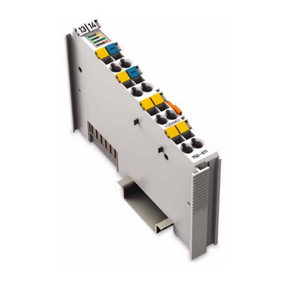
Page 43: Indicators
Input DI 1: Signal level (1) 13 14 Input DI 2: Signal level (0) Status fixed DI 2 green Input DI 2: Signal level (1) Status Fig. 2.1.2-5: Indicators No system voltage present fixed System g067002x green System voltage present voltage WAGO-I/O-SYSTEM 750 I/O Modules... - Page 44 1, or the drive is braking the unit. flashing Write access to EEPROM Write access 10 Hz to EEPROM/ Error Error code red, Group error, Group error Blink- Error message (cf. Chapter 3.3, “Error code Blink Codes”) issued WAGO-I/O-SYSTEM 750 I/O Modules...
-
Page 45: Operating Elements
Operating Elements 2.1.2.4 Operating Elements The stepper controller 750-671 is not equipped with any operating elements. Changes to the configuration or parameters are made using the higher-order control too, or the WAGO-I/O-CHECK configuration tool. 2.1.2.5 Schematic Diagram DI1+ DI2+ DI1+... -
Page 46: Technical Data
Voltage via power jumper contacts 24 V DC (-15 % ... +20 %) Protected against reverse polarity Current via power jumper contacts 10 A max. Electrical isolation 500 V DC system voltage / field level (power jumper contacts) WAGO-I/O-SYSTEM 750 I/O Modules... - Page 47 Approvals (See Section 2.2 of the Coupler/Controller Manual) Conformity marking 1) The figures are peak values 2) Detection system is not available 100 % 80 % 70 % 60 % 40 % 20 % Ambient operating temperature [°C] Fig. 2.1.2-8: Derating graph g067121e WAGO-I/O-SYSTEM 750 I/O Modules...
-
Page 48: Process Image
Status byte S1 Control byte C1 Switching between the two process images is conducted through bit 5 in the control byte (C0 (C0.5). Activation of the mailbox is acknowledged by bit 5 of the status byte S0 (S0.5). WAGO-I/O-SYSTEM 750 I/O Modules... -
Page 49: Control Byte 0, Status Byte 0
This means that errors will not result in a bit being set. 0: No error present. 1: Error present. Reserved Configuration of the control and status bytes C1 ... C3 and S1 ... S3 depends on the set operating mode; this is described in the associated sections. WAGO-I/O-SYSTEM 750 I/O Modules... -
Page 50: Cyclic Process Image
The configuration of the process data depends on the set operating mode; this is described in the associated sections. A basic distinction is drawn between the following process images: - Positioning, - Jogging, - Move program, - Velocity. WAGO-I/O-SYSTEM 750 I/O Modules... -
Page 51: Mailbox Process Image
Control byte C3 Status byte S2 Control byte C2 Status byte S1 Control byte C1 The individual applications can be set using opcodes. Opcodes are assigned to different topical areas and are described in the sections that follow. WAGO-I/O-SYSTEM 750 I/O Modules... - Page 52 The return messages are then individual. Toggle Flag The mailbox is evaluated when the status of the toggle flag is different in the Control_MBX. The status of the bit is then also changed. WAGO-I/O-SYSTEM 750 I/O Modules...
-
Page 53: Mailbox Mode
EEPROM, it will be copied automatically to RAM1 and RAM2 following a reset and is activated such that it can be directly executed in RAM1. The tables are loaded from the control system by download. The following rules apply to downloading: WAGO-I/O-SYSTEM 750 I/O Modules... - Page 54 The table for the camshaft stores a bit sample that is output as a function of the position. Activation of a different table for the camshaft is performed immediately. The table for configuration stores a data field that contains configuration data. WAGO-I/O-SYSTEM 750 I/O Modules...
-
Page 55: Download
I/O table and are assigned to fixed targets in the same table. The bit I/O table is broken down into two sectors: Addresses 0 ... 127 describe the data sources; addresses 128 ... 255 described the targets to which the indicator can point. WAGO-I/O-SYSTEM 750 I/O Modules... -
Page 56: Configuration Table
Reserved Positioning controller Velocity control Freq_Div UINT16 200 4 ... 65535 Sets the prescaler for the maximum velocity Acc_Fact UINT16 80 1 ... 65535 Sets factor for maximum acceleration WAGO-I/O-SYSTEM 750 I/O Modules... -
Page 57: Configuration Of Basic Parameters
Mode for referencing on start of a reference run using the control bit M_Reference. At the start of a reference run via the mailbox using the Move command START_REFERENCING, the call parameters are used (and NOT the following configuration bits). WAGO-I/O-SYSTEM 750 I/O Modules... - Page 58 Acceleration_RampDown, Offset 50, Range [0 ... 32767] Default acceleration for delay phase. Acceleration_RampUp_Param, Offset 52, Range [0 ... 16777216] Default acceleration time or acceleration path Acceleration_RampDown_Param, Offset 56, Range [0 ... 16777216] Default deceleration time or deceleration path Acceleration_Modes, Offset 60 WAGO-I/O-SYSTEM 750 I/O Modules...
- Page 59 (path in m, mm, degrees, and velocities in m/s, degrees/s). Conversion is performed by multiplying by a configurable factor *_Mult and then dividing by a configurable factor *_Div. This way, fractions can be set with high accuracy within a wide range. WAGO-I/O-SYSTEM 750 I/O Modules...
- Page 60 Output signal: Direction of rotation inverted Bit 3 … 6: Reserved Bit 7: Program_Autostart (Move program Autostart – Normal mode) Move program activated only via Move program or Mailbox mode. Move program activated immediately after startup, see description. WAGO-I/O-SYSTEM 750 I/O Modules...
-
Page 61: Configuration Using Control Byte C2
The acceptable velocity range is 1 … 25000. The setting for the pulse frequency in [Hz] is given by selecting Freq_Prescaler = 80. Note The bits Freq_Range_Sel may only be modified when the control system is deactivated! These bits are therefore only accepted when Enable is not set. WAGO-I/O-SYSTEM 750 I/O Modules... -
Page 62: Acceleration Factor
Acceleration is set in [Hz/s] when the acceleration factor Acc_Multiplier is selected equal to the prescaler Freq_Prescaler. Note The bits Acc_Range_Sel may only be modified when the control system is deactivated! These bits are therefore only accepted when Enable is not set. WAGO-I/O-SYSTEM 750 I/O Modules... -
Page 63: Configuration Via Mailbox Mode
If a valid configuration data set is available in the EEPROM after power-on, reset or a warm start of the module, this data set is loaded to the RAM; if not, the factory default data set is loaded, i.e. the module is restored to the WAGO as-delivered status. -
Page 64: Linking Of Bits
The prefix Ptr is placed in front of the identifier. The standard link between the source and target is entered in the column "Target/Source". This corresponds to the WAGO default settings (FACTORY_DEFAULT). 2.1.2.10.5 Linking of Bits The expanded parameters are set using pointers (indices). - Page 65 … Linkable bits can be programmed for any source. This "linkability" enables flexible configuration and flexible arrangement of module terminal assignments. For example, the Start linkable bit can be set to the Input 1 fixed bit. WAGO-I/O-SYSTEM 750 I/O Modules...
- Page 66 0x00 0 ... 255 Source for linkable bit 0xA8 Ptr_Direction_ 0xBB UINT8 0x53 0 ... 255 Source for linkable bit 0xBB … Filter1_Function 224 0xE0 UINT8 0 ... 11 Function of filter: 1 = inversion … WAGO-I/O-SYSTEM 750 I/O Modules...
-
Page 67: Special Bits: Zero, One, Mzero And Mone
Move program. A bit that is linked to MONE is initially set after a reset and is otherwise treated the same as a bit linked to MZERO. WAGO-I/O-SYSTEM 750 I/O Modules... -
Page 68: Filters, Low Pass, Timers And Counters
The functions Low pass, Pulse extension, Monoflop and Pulse delay react to the linkable input bit and trigger the output in accordance with the selected function at a time constant for which parameters can be assigned. This time can be set between 0 … 16777215 ms. WAGO-I/O-SYSTEM 750 I/O Modules... - Page 69 An operational change back to the Wait status is not provided. Fig. 2.1.2-12: Starting edge filter p067021x The Low pass does not accept any change of the input signal until the new status is constant during the runtime. WAGO-I/O-SYSTEM 750 I/O Modules...
- Page 70 10 edge. Retriggering during the runtime is possible. Fig. 2.1.2-14: Pulse extension 500ms p067023x The monoflop function sets the output on an input 01 edge. The output is reset after the set time expires. Retriggering during the runtime is not possible. WAGO-I/O-SYSTEM 750 I/O Modules...
- Page 71 Pulse extension sets the output when the set time has expired after an input 01 edge. The output is reset as soon as the input is deactivated. The output is not reset if the input is deactivated before the set time expires. Fig. 2.1.2-17: Pulse delay 500ms p067026x WAGO-I/O-SYSTEM 750 I/O Modules...
- Page 72 "Counter, up" / "Counter, down", except that counting is halted when the filter value reaches zero. What this also means is that the filter value must have a starting value other than zero, with subsequent counting then performed to zero. WAGO-I/O-SYSTEM 750 I/O Modules...
-
Page 73: Move Commands
Switching between the other setpoint sources is performed by selecting the corresponding mode. A Move program is used to execute individual movements one after the other. Some values can also be set using the Move program. WAGO-I/O-SYSTEM 750 I/O Modules... -
Page 74: Scaling, Number Ranges And Units
On account of the periodical processing employed, time is measured in TICKS, with a TICK being the duration of one scan interval. A TICK is equal to one millisecond. Physical units based on time are converted accordingly. WAGO-I/O-SYSTEM 750 I/O Modules... - Page 75 For example, if a stepper motor is to operate at 200 steps and 64 microsteps at speeds between 0 … 20 s , a Freq_Prescaler range of 4 ... 7 is possible. A setting of Freq_Prescaler = 7 provides the highest degree of accuracy and frequency resolution. WAGO-I/O-SYSTEM 750 I/O Modules...
- Page 76 Speed_Mult prior to internal processing and then divided by a factor Speed_Div. If the internal external or external internal conversion violates the permissible value range, the error message 1513 (UNITS_SPEED_INT_RESULT) or 1514 (UNITS_SPEED_USER_RESULT) is issued. WAGO-I/O-SYSTEM 750 I/O Modules...
-
Page 77: External Units Of Measure
Pos_Mult = 25 and Pos_Div = 3. If the internal external or external internal conversion violates the permissible value range, the error message 1511 (UNITS_POS_INT_RESULT) or 1516 (UNITS_POS_USER_RESULT) is issued. WAGO-I/O-SYSTEM 750 I/O Modules... -
Page 78: Positioning
2.1.2.11.1 Operation via Cyclic Process Image Different operating modes are available with the stepper modules. These are described in the following sections. The application Stepper positioning control is selected using the configuration parameter Application_Selector = 1. WAGO-I/O-SYSTEM 750 I/O Modules... -
Page 79: Selecting A Mode
This is also normally associated with step losses, meaning a reference run must subsequently be started. WAGO-I/O-SYSTEM 750 I/O Modules... -
Page 80: Sequence Diagram For Selection And Ending Of Modes
Mode 2 is selected. (10) Mode 2 has been accepted by the module. (11) The drive is started by the Start rising edge in Mode 1. (12) Start can be canceled if the Start_ACK bit has been set. WAGO-I/O-SYSTEM 750 I/O Modules... -
Page 81: Positioning Mode
= const.With constant acceleration the new set up value is taken over during the ramps. The special features associated with limit switches and the Jog and Referencing modes are described in the corresponding sections. WAGO-I/O-SYSTEM 750 I/O Modules... - Page 82 D5 Actual position M D5 Target position M D6 Actual position H D6 Target position H Status byte S3 C3 Control byte C3 Status byte S2 C2 Control byte C2 Status byte S1 C1 Control byte C1 WAGO-I/O-SYSTEM 750 I/O Modules...
- Page 83 Move commands via mailbox mode. In this mode, all movement commands are issued directly via the mailbox. 0: The Move commands via mailbox mode is not active (selected). 1: The Move commands via mailbox mode is active (selected). WAGO-I/O-SYSTEM 750 I/O Modules...
- Page 84 Move commands via mailbox mode active. In this mode, all movement commands are selected directly via the mailbox. 0: The Move commands via mailbox mode is not active (selected). 1: The Move commands via mailbox mode is active (selected). WAGO-I/O-SYSTEM 750 I/O Modules...
- Page 85 Start. Error_Quit Acknowledge error. All errors that are present are acknowledged at the rising edge from 0 to 1. After acknowledgement, the error switches to 0, or a new error is present: Reserved WAGO-I/O-SYSTEM 750 I/O Modules...
- Page 86 0: Precalculation not yet completed, or no request received. 1: Precalculation completed. Error Common error for module An error can/must be acknowledged using Error_Quit. 0: No error present for the drive. 1: Error present for the drive. WAGO-I/O-SYSTEM 750 I/O Modules...
- Page 87 This also occurs after saving the user configuration to the EEPROM. Volatile data, parameters and tables for the module may be inconsistent and must be reloaded to ensure proper operation. 0: Function not defined. 1: The Reset signal is reset. Reserved WAGO-I/O-SYSTEM 750 I/O Modules...
- Page 88 Reset status bit; this must be acknowledged using Reset_Quit. This also occurs after saving the user configuration to the EEPROM. Volatile data, parameters and tables for the module may be inconsistent and must be reloaded to ensure proper operation. Reserved WAGO-I/O-SYSTEM 750 I/O Modules...
- Page 89 The drive is restarted by the Start rising edge. The current setpoint from the process image is accepted, the patch recalculated and movement made toward the target position, where applicable, on the fly. Start can be canceled after Start_ACK has been set. WAGO-I/O-SYSTEM 750 I/O Modules...
-
Page 90: Referencing Mode
In the Mailbox mode the call of the command START_REFERENCING is acknowledged by error message 23. No error message is issued in the Referencing mode. In this case, the ERR_RANGE_NEG, or ERR_RANGE_POS bit is set and can then be evaluated. WAGO-I/O-SYSTEM 750 I/O Modules... - Page 91 The Referencing mode has been accepted by the module. The drive is started by the Start rising edge. The reference run is started. Start can be canceled if Start_ACK has been set. The reference point has been moved to and set. WAGO-I/O-SYSTEM 750 I/O Modules...
- Page 92 Fig. 2.1.2-23: Referencing to positive end of reference switch, with start in negative direction from negative movement range g067x14e Start Limit switch Reference Limit switch negative switch positive Fig. 2.1.2-24: Referencing to positive end of reference switch with start in negative direction from limit switch g067x13e WAGO-I/O-SYSTEM 750 I/O Modules...
- Page 93 Fig. 2.1.2-25: Referencing at the negative end of reference switch with start in negative direction from positive movement range g067x11e Start Limit switch Reference Limit switch negative switch positive Fig. 2.1.2-26: Referencing at the negative end of reference switch with start in negative direction from negative movement range g067x12e WAGO-I/O-SYSTEM 750 I/O Modules...
- Page 94 1 Parameter 3 Bit 2 1 Referencing to positive end , Bit 1 Start Limit switch Reference Limit switch negative switch positive Fig. 2.1.2-28: Refderencing at positive end of reference switch with start in positive direction from positive movement range g067x16e WAGO-I/O-SYSTEM 750 I/O Modules...
- Page 95 Fig. 2.1.2-30: Referencing to limit switch with start in negative direction from positive limit switch g067x39e Start Limit switch Limit switch negative positive Fig. 2.1.2-31: Referencing to negative limit switch with start in negative direction from positive movement range g067x40e WAGO-I/O-SYSTEM 750 I/O Modules...
-
Page 96: Jog And Stepping Mode
JOG command. 2.1.2.11.1.6.1 Jog and Stepping Mode Process Image This process image is different from the standard configuration for stepper positioning control and is shown in the table below. WAGO-I/O-SYSTEM 750 I/O Modules... - Page 97 Status byte S2 C2 Control byte C2 Status byte S1 C1 Control byte C1 The function of the control and status bytes corresponds to the standard configuration for stepper positioning control given in Chapter 2.1.2.11.1.4.1, “Positioning Process Image”. WAGO-I/O-SYSTEM 750 I/O Modules...
- Page 98 Start can be canceled if Start_ACK has been set. The drive is restarted by the Start rising edge. The Jog mode is activated, the drive can be started using the pushbutton Direction_Pos and Direction_Neg. Start can be canceled if Start_ACK has been set. WAGO-I/O-SYSTEM 750 I/O Modules...
-
Page 99: Move Program Mode
This bit can be queried using the mailbox command GET_BIT. The On_Target and Busy bits are controlled by the individual program commands. When the bit SetupSpeed_Active_ACK is set at the same time for setup, speed is limited to the defined setup speed. WAGO-I/O-SYSTEM 750 I/O Modules... - Page 100 Status byte S2 C2 Control byte C2 Status byte S1 C1 Control byte C1 The function of the control and status bytes corresponds to the standard configuration for stepper positioning control given in Chapter 2.1.2.11.1.4.1, “Positioning Process Image”. WAGO-I/O-SYSTEM 750 I/O Modules...
- Page 101 The drive is restarted by the Start rising edge. The Move program in progress will be terminated and the drive set to standstill. The Move program is then restarted on the first command. Start can be canceled if Start_ACK has been set. WAGO-I/O-SYSTEM 750 I/O Modules...
- Page 102 Move to position 65065 0x71 0x30 0x00 0x00 Query, Input 1 = "0" 0x02 0x00 0x00 0x00 Move to position 0 0xF5 0x02 0x00 0x00 Go to line 2 0x70 0xD0 0x07 0x00 Wait 2000 ms WAGO-I/O-SYSTEM 750 I/O Modules...
- Page 103 Reset. The bit is reset by Reset_Quit. A Move program is started only one time after each reset by HwSwConfig.Program_AutoStart. A Move program started with HwSwConfig.Program_AutoStart is always started at an address of 0. WAGO-I/O-SYSTEM 750 I/O Modules...
-
Page 104: Move Mode Via Mailbox
If movement is made to a limit switch in the Positioning mode, the drive will brake the movement until standstill using the defined deceleration Acceleration_Stop_Fast. The drive can only be started in the Jog and Referencing modes when it is located at a limit switch. WAGO-I/O-SYSTEM 750 I/O Modules... -
Page 105: Software Limit Switch
(software limit switches), for example if no hardware limit switches are available. Note Evaluation of the hardware limit switches has priority over evaluation of the software limit switches. WAGO-I/O-SYSTEM 750 I/O Modules... - Page 106 In this mode the drive can also be operated outside the movement range defined by the software limit switches with repeated JOG commands. The software limit switches are not active again until the drive is back within the defined range. WAGO-I/O-SYSTEM 750 I/O Modules...
-
Page 107: Expanded Positioning Functions
The actual value, however, is reported only within the range 0 … 2π; the number of completed revolutions can not be determined. The direction of movement depends on the sign for the relative setpoint. WAGO-I/O-SYSTEM 750 I/O Modules... -
Page 108: Absolute Positioning
In contrast to other setpoints, the switching positions for the camshaft are always given in "microsteps". Conversion from or to other user-specific units is not provided for. The Camshaft table can not be edited in the module, but must be downloaded completely. WAGO-I/O-SYSTEM 750 I/O Modules... -
Page 109: Position Table
2.1.2.12.3.1 Teaching of Positions Teaching of positions using the mailbox command POS_TABLE_TEACH allows the current actual value to the saved in the position table so that it is available as a target for a Move task. WAGO-I/O-SYSTEM 750 I/O Modules... -
Page 110: Control Of A Motor Brake
Brake_Manual bit (see Chapter 3.4, „Bit field for I/O driver“). This bit can be set and canceled externally and can also, for example, be linked to a camshaft channel so that it is switched as a function of position. WAGO-I/O-SYSTEM 750 I/O Modules... -
Page 111: Other Applications
If parameters have been provided for the value Rotary_Axis_Period, this value is used for the rotary axis. Step positioning/Stepper control contains a detailed description of this (selection of mode using M_Positioning and accepting of setpoints with Start). WAGO-I/O-SYSTEM 750 I/O Modules... -
Page 112: Velocity Control Process Image
The function of the bits in control bytes C1 ... C3 and in status bytes S1 … S3 are determined by the Frequency/Speed control application. When switchover is made to this application, the linked locations for the old application are retained. The meaning of the bits for the standard configuration are explained below. WAGO-I/O-SYSTEM 750 I/O Modules... - Page 113 Move commands via mailbox mode. In this mode, all movement commands are issued directly via the mailbox. 0: The Move commands via mailbox mode is not active (selected). 1: The Move commands via mailbox mode is active (selected). WAGO-I/O-SYSTEM 750 I/O Modules...
- Page 114 Move commands via mailbox mode active. In this mode, all movement commands are selected directly via the mailbox. 0: The Move commands via mailbox mode is not active (selected). 1: The Move commands via mailbox mode is active (selected). WAGO-I/O-SYSTEM 750 I/O Modules...
- Page 115 0: Precalculation not yet completed, or no request received. 1: Precalculation completed. Error Drive error status. An error can be acknowledged using Error_Quit. 0: No error present for the drive. 1: Error present for the drive. Reserved WAGO-I/O-SYSTEM 750 I/O Modules...
- Page 116 Reset_Quit. 0: No reset since last confirmation. 1: A reset has been carried out but not yet confirmed with Reset_Quit. Volatile data, parameters and tables for the module may be inconsistent and must be reloaded. Reserved WAGO-I/O-SYSTEM 750 I/O Modules...
-
Page 117: Advanced Diagnostics
(see "Internal Status Variables"). The configuration value Trace_MsecCycleTime denotes the scan (cycle) time in Configuration value Meaning Trace_Var1 Index for first recording variable Trace_Var2 Index for second recording variable Trace_MsecCycleTime Scan time in ms WAGO-I/O-SYSTEM 750 I/O Modules... - Page 118 This is accomplished by entering the corresponding link in the configuration table. The control system can also initiate recording using the mailbox commands GET_BIT and SET_BIT. The trigger bits must be linked to the MONE internal bit for this. WAGO-I/O-SYSTEM 750 I/O Modules...
-
Page 119: Connection Example
750-671 [Steppercontroller] • 119 Connection Example 2.1.2.15 Connection Example DI1+ 24 V DI2+ Input for external release with 24 V switched! 750-671 Fig. 2.1.2-36: Connection of bipolar stepper motors g067010e WAGO-I/O-SYSTEM 750 I/O Modules... -
Page 120: Appendix
Set address for data access to the CONFIG_SET_PTR 0x50 configuration CONFIG_WR 0x51 Write access to configuration value CONFIG_RD 0x52 Read access to configuration value CONFIG_SAVE 0x53 Saves the current RAM configuration CONFIG_RESTORE 0x54 Restores the configuration WAGO-I/O-SYSTEM 750 I/O Modules... - Page 121 Sets an index for the subsequent entry to POS_TABLE_SET_PTR 0x5D be written with POS_TABLE_WR in the position table Writes an entry to the active position POS_TABLE_WR 0x5E table Writes the current position to the active POS_TABLE_TEACH 0x5F position table WAGO-I/O-SYSTEM 750 I/O Modules...
-
Page 122: Overview Of Mailbox Commands, Sorted By Opcodes
Sets an index for the subsequent entry to POS_TABLE_SET_PTR 0x5D be written with POS_TABLE_WR in the position table Writes an entry to the active position POS_TABLE_WR 0x5E table Writes the current position to the active POS_TABLE_TEACH 0x5F position table WAGO-I/O-SYSTEM 750 I/O Modules... -
Page 123: Overview Of Mailbox Commands, Sorted By Functions
Writes an entry to the active position POS_TABLE_WR 0x5E table TABLE_COPY 0x45 Tables being copied ... TABLE_ERASE 0x44 Tables being deleted ..TABLE_GET_ACTIVE 0x4F Determine active table TABLE_START 0x46 Activates a table TABLE_STOP 0x48 Ends table processing WAGO-I/O-SYSTEM 750 I/O Modules... -
Page 124: Reference Commands - Mailbox Commands
3.1.4.1.1 IDLE (0x00) No task is performed if the value for "Opcode" is 0. Request Byte 0x00 Reserved Reserved Reserved Reserved Response Byte 0x00 Return Code Reserved Reserved Reserved Reserved Return 0x00: Code 0x01: General error WAGO-I/O-SYSTEM 750 I/O Modules... -
Page 125: Move Commands
Data 3 Return 0x00: Code 0x01: General error 0x11: The last command is still being executed 0x12: Command not accepted, for example, when a Move command has not yet been completed. 0x13: Unknown command 0x23: Access denied WAGO-I/O-SYSTEM 750 I/O Modules... -
Page 126: Download Commands
/ a camshaft table. MB 4…6 are ignored for an 8-bit command / data sample. Compressed 24-bit down-/upload When downloading a Move program / a camshaft table, those items are transferred with a DLD_CONT command for an 8-bit command / data sample and a 24-bit date entry / position entry. WAGO-I/O-SYSTEM 750 I/O Modules... - Page 127 RAM Table 1 2 ... 255: Reserved Table type Reserved Move program: Camshaft Position table Configuration data set, User configuration Trace Transfer 24-bit data download 24-bit data upload 32-bit data download 32-bit data upload 4 ... 255: Reserved WAGO-I/O-SYSTEM 750 I/O Modules...
- Page 128 128 • Reference Commands – Mailbox Commands Download Commands Response Byte 0x41 Return Code Status Reserved Number of data sets EEPROM version number Return 0x00: Code 0x30: Table being used 0x31: General error Status Download/Upload can be started Error; Download/Upload not possible WAGO-I/O-SYSTEM 750 I/O Modules...
-
Page 129: Dld_Cont (0X42)
… Compressed 24-bit down-/upload When downloading a Move program / a camshaft table, those items are transferred with a DLD_CONT command for an 8-bit command / data sample and a 24-bit date entry / position entry: WAGO-I/O-SYSTEM 750 I/O Modules... - Page 130 Only 32-bit data exists for the position tables (Type 03) and the configuration data set (Type 04). Therefore, only the 32-bit down-/upload are given for both types of tables. Request Byte 0x42 Data Data Data Data WAGO-I/O-SYSTEM 750 I/O Modules...
- Page 131 Reference Commands – Mailbox Commands • 131 Download Commands Response Byte 0x42 Return Code Data Data Data Data Return 0x00: Code 0x31: Upload/Download not started, or all data have already been transferred 0x38: Transferred data set corrupt WAGO-I/O-SYSTEM 750 I/O Modules...
-
Page 132: Dld_End (0X43)
Checksum for transferred data Checksum for transferred data (MSB) Response Byte 0x43 Return Code Checksum for stored data (LSB) Checksum for stored data Checksum for stored data Checksum for stored data (MSB) Return 0x00: Code 0x31: General error WAGO-I/O-SYSTEM 750 I/O Modules... -
Page 133: Table_Erase (0X44)
Storage location Table type Reserved Reserved Storage EEPROM table location RAM Table 1 RAM Table 2 3 ... 255: Reserved Table type Reserved Move program: Camshaft Position table Configuration data set, User configuration 5 ... 255: Reserved WAGO-I/O-SYSTEM 750 I/O Modules... - Page 134 0x30: Table active 0x31: General error Status Successfully deleted Deleting aborted Table manager EEPROM RAM2 RAM2 RAM1 WAGO Factory User User User User R/W + ERA + CPY R/W + R/W + ERA + ERA + Move program Move program...
-
Page 135: Table_Copy (0X45)
This command can not be used for copying out of the EEPROM. A configuration table can not be copied with this command (see also CFG_SAVE, CONFIG_RESTORE). Copying options: 1. RAM RAM 2. RAM EERPOM WAGO-I/O-SYSTEM 750 I/O Modules... - Page 136 Status query for a previous copying process (see also DIAG_QUERY_STORAGE) 6 ... 255: Reserved Data source Reserved RAM Table 1 RAM Table 2 3 ... 255: Reserved Storage EEPROM table target RAM Table 1 RAM Table 2 3 ... 255: Reserved WAGO-I/O-SYSTEM 750 I/O Modules...
- Page 137 Table Management Commands Response Byte 0x44 Return Code Status Reserved Reserved Reserved Return 0x00: Code 0x31: General error 0x33: Copying process still active 0x34: EEPROM copying process aborted 0x35: Target table not empty Status Successfully copied Copying aborted WAGO-I/O-SYSTEM 750 I/O Modules...
-
Page 138: Table_Start (0X46)
3 ... 255: Reserved Table type Reserved Move program: Camshaft Position table 4 ... 255: Reserved Response Byte 0x46 Return Code Status Reserved Reserved Reserved Return 0x00: Code 0x31: General error Status Successfully activated Activation aborted WAGO-I/O-SYSTEM 750 I/O Modules... -
Page 139: Table_Stop (0X48)
The last command is still being executed previous 0x12: Command not accepted, for example, when a Move command command has not yet been completed. SPEED_ STOP_ 0x23: Access denied IMM) Status exact error code, when return code <> 0 WAGO-I/O-SYSTEM 750 I/O Modules... -
Page 140: Table_Get_Active (0X4F)
No table active (even when 0x31 returned) type 1, 2, RAM Table 1 active RAM Table 2 active 3 … 255: Reserved Table Reserved (even when 0x31 returned) type 4 User data set active Factory default active 3 … 255: Reserved WAGO-I/O-SYSTEM 750 I/O Modules... -
Page 141: Diagnostics Commands
Information about error is retrieved from the error memory. Request Byte 0x49 Reserved Reserved Reserved Reserved Response Byte 0x49 Return Code Error code (LSB) Error code (MSB) Extra information (LSB) Extra information (MSB) Return 0x00: Code WAGO-I/O-SYSTEM 750 I/O Modules... -
Page 142: Diag_Quit_Error (0X4A)
142 • Reference Commands – Mailbox Commands Diagnostics Commands 3.1.4.5.2 DIAG_QUIT_ERROR (0x4A) Terminates a device error condition. Request Byte 0x4A Reserved Reserved Reserved Reserved Response Byte 0x4A Return Code Reserved Reserved Reserved Reserved Return 0x00: Code WAGO-I/O-SYSTEM 750 I/O Modules... -
Page 143: Diag_Rd_Var (0X4C)
Direct reading out of RAM 0x40004000: 0xE0000000 … Direct reading out of controller periphery 0xE0200000: 0xFFE00000 … Direct reading out of controller periphery 0xFFFFFFFF: Response Byte 0x4C Return Code Variable (LSB) Variable Variable Variable (MSB) Return 0x00: Code WAGO-I/O-SYSTEM 750 I/O Modules... -
Page 144: Diag_Rd_Bit (0X4D)
Byte 0x4D Bit number Reserved Reserved Reserved Bit number 0 ... 255: Specifies which predefined bit is being requested. Response Byte 0x4D Return Code Status Reserved Reserved Reserved Return 0x00: Code Status Bit deleted Bit set WAGO-I/O-SYSTEM 750 I/O Modules... -
Page 145: Diag_Query_Storage (0X4E)
DIAG_QUERY_STORAGE (0x4E) Read out storage process status bit Request Byte 0x4E Reserved Reserved Reserved Reserved Response Byte 0x4E Return Code Status Reserved Reserved Reserved Return 0x00: Code Status Storing completed 1 ... 255: Storing in progress WAGO-I/O-SYSTEM 750 I/O Modules... -
Page 146: Configuration Table Commands
Number of bytes that are written for access with Config_WR. 5 ... 255: Reserved Response Byte 0x50 Return Code Reserved Reserved Reserved Reserved Return 0x00: Code 0x23: Access denied; invalid number of bytes or invalid index WAGO-I/O-SYSTEM 750 I/O Modules... -
Page 147: Config_Wr (0X51)
• 147 Configuration Table Commands 3.1.4.6.2 CONFIG_WR (0x51) Write access to configuration value. Request Byte 0x51 Data (LSB) Data Data Data (MSB) Response Byte 0x51 Return Code Reserved Reserved Reserved Reserved Return 0x00: Code 0x23: Access denied WAGO-I/O-SYSTEM 750 I/O Modules... -
Page 148: Config_Rd (0X52)
Reserved Number of Reserved bytes 1 ... 4: Number of bytes that are written for access with Config_RD. 5 ... 255: Reserved Response Byte 0x52 Return Code Data (LSB) Data Data Data (MSB) Return 0x00: Code WAGO-I/O-SYSTEM 750 I/O Modules... -
Page 149: Config_Save (0X53)
The Reset status bit is set after the warm start; this must be canceled using Reset_Quit. Only then is the module operational again. Request Byte 0x53 Password (LSB) Password Password Password (MSB) Response Byte 0x53 Return Code Reserved Reserved Reserved Reserved Return 0x00: Code 0x31: Fault WAGO-I/O-SYSTEM 750 I/O Modules... -
Page 150: Config_Restore (0X54)
The required data set is only loaded to the RAM, without a warm start being performed. Error 2821 = CFG_FACTORY_LOAD is reported. A warm start is carried out only when this error is acknowledged, with the original configuration being restored. 2 ... 255: Reserved WAGO-I/O-SYSTEM 750 I/O Modules... - Page 151 Reference Commands – Mailbox Commands • 151 Configuration Table Commands Response Byte 0x54 Return Code Reserved Reserved Reserved Reserved Return 0x00: Code 0x31: Fault WAGO-I/O-SYSTEM 750 I/O Modules...
-
Page 152: Position Table Commands
Is executed only when the new size is larger than the existing table! Response Byte 0x5C Return Code Status Reserved Reserved Reserved Return 0x00: Code 0x32: Invalid table specified 0x3A: Invalid number of elements Status Initialization successful Initialization aborted WAGO-I/O-SYSTEM 750 I/O Modules... -
Page 153: Pos_Table_Set_Ptr (0X5D)
Reserved Index 0 ... 49: Index 50 ... 255: Reserved Response Byte 0x5D Return Code Status Reserved Reserved Reserved Return 0x00: Code 0x37: Table does not exist, or index not assigned Status Successfully indexed Indexing aborted WAGO-I/O-SYSTEM 750 I/O Modules... -
Page 154: Pos_Table_Wr (0X5E)
Save value (LSB) Save value Save value Save value (MSB) Response Byte 0x5E Return Code Status Reserved Reserved Reserved Return 0x00: Code 0x37: Table does not exist, or index not set Status Writing completed successfully Writing aborted WAGO-I/O-SYSTEM 750 I/O Modules... -
Page 155: Pos_Table_Teach (0X5F)
The current position is the zero point for a relevant measurement 50 ... 252: Reserved Measureme Absolute measurement: Save current position Relative measurement: Zero point for relative measurement – save current position 2 ... 255: Reserved WAGO-I/O-SYSTEM 750 I/O Modules... - Page 156 156 • Reference Commands – Mailbox Commands Position table commands Response Byte 0x5F Return Code Status Reserved Reserved Reserved Return 0x00: Code 0x37: Table or specified index does not exist Status Writing completed successfully Writing aborted WAGO-I/O-SYSTEM 750 I/O Modules...
-
Page 157: Commands For Move Mode
Velocity to target position. Valid only SET_VELOCITY_ for the next positioning process and is 0x2B TARGET then reset automatically to zero after the next positioning process. The current position is applied to the SET_ACTUALPOSITON 0x2E transferred value. WAGO-I/O-SYSTEM 750 I/O Modules... - Page 158 Continues table process from a defined GOTO_LABEL 0xF8 label. Continues table processing for a defined GOTO_LABEL_IF 0xF9 label if a bit has been set. WAGO-I/O-SYSTEM 750 I/O Modules...
- Page 159 Overview of Commands for Move Mode • 159 Position table commands Function Opcode Meaning Page Continues table processing for a defined GOTO_LABEL_IF_NOT 0xFA label if a bit has been deleted. LABEL 0xFB Defines a label for a step target WAGO-I/O-SYSTEM 750 I/O Modules...
-
Page 160: Overview Of Move Mode Commands, Sorted By Opcodes
0x2B TARGET then reset automatically to zero after the next positioning process. The current position is applied to the SET_ACTUALPOSITON 0x2E transferred value. SET_ACTUALPOSITION_ 0x2F The current position is set to zero ZERO WAGO-I/O-SYSTEM 750 I/O Modules... - Page 161 Continues table processing for a defined GOTO_LABEL_IF 0xF9 label if a bit has been set. Continues table processing for a defined GOTO_LABEL_IF_NOT 0xFA label if a bit has been deleted. LABEL 0xFB Defines a label for a step target WAGO-I/O-SYSTEM 750 I/O Modules...
-
Page 162: Overview Of Move Mode Commands, Sorted By Function
PARAM_DOWN positioning process. Set the Acc_ParamUp parameter for SET_ACC_PARAM_UP 0x23 acceleration; valid as of the next positioning process. Sets the acceleration and deceleration SET_ACC_MODE 0x21 mode. SET_ACTUALPOSITION_ 0x2F The current position is set to zero ZERO WAGO-I/O-SYSTEM 750 I/O Modules... - Page 163 Before processing the next command WAIT_TEST_BIT 0x71 waits until the specified bit has the status 0 or 1. Waits a defined time period before WAIT_TIME 0x70 processing the next command. WR_BIT 0x78 Sets a bit to 0 or 1. WAGO-I/O-SYSTEM 750 I/O Modules...
-
Page 164: Reference Commands For Move Mode
"On_Target" bit has been set. The acceleration and velocity specified by SET_ACC (0x22) and SET_VELOCITY (0x25) are used for positioning commands. Request Byte 0x40 0x02 Position (LSB) Position Position (MSB) Response Byte 0x40 Return Code 0x02 Reserved Reserved Reserved WAGO-I/O-SYSTEM 750 I/O Modules... -
Page 165: Move_Immediate (0X03)
The acceleration and velocity specified by SET_ACC (0x22) and SET_VELOCITY (0x25) are used for positioning commands. Request Byte 0x40 0x03 Position (LSB) Position Position (MSB) Response Byte 0x40 Return Code 0x03 Reserved Reserved Reserved WAGO-I/O-SYSTEM 750 I/O Modules... -
Page 166: Move_Table (0X04)
SET_VELOCITY (0x25) are used for positioning commands. Request Byte 0x40 0x04 No. of table entry with target position Reserved Reserved Read out from position table. Read out from variables FILT1 ... FILT8. Response Byte 0x40 Return Code 0x04 Reserved Reserved Reserved WAGO-I/O-SYSTEM 750 I/O Modules... -
Page 167: Move_Table_Immediate (0X05)
SET_VELOCITY (0x25) are used for positioning commands. Request Byte 0x40 0x05 No. of table entry with target position Reserved Reserved Read out from position table. Read out from variables FILT1 ... FILT8. Response Byte 0x40 Return Code 0x05 Reserved Reserved Reserved WAGO-I/O-SYSTEM 750 I/O Modules... -
Page 168: Move_Rel (0X06)
The acceleration and velocity specified by SET_ACC (0x22) and SET_VELOCITY (0x25) are used for positioning commands. Request Byte 0x40 0x06 Position (LSB) Position Position (MSB) Antwort Byte 0x40 Return Code 0x06 Reserved Reserved Reserved WAGO-I/O-SYSTEM 750 I/O Modules... -
Page 169: Move_Table_Rel (0X08)
SET_ACC (0x22) and SET_VELOCITY (0x25) are used for positioning commands. Request Byte 0x40 0x08 No. of table entry with target position Reserved Reserved Read out from position table. Read out from variables FILT1 ... FILT8. Response Byte 0x40 Return Code 0x08 Reserved Reserved Reserved WAGO-I/O-SYSTEM 750 I/O Modules... -
Page 170: Speed (0X10)
"On_Target" bit has been set. Speed range: -25000 … 25000. Request Byte 0x40 0x10 Speed (LSB) Speed (MSB) Reserved Response Byte 0x40 Return Code 0x10 Reserved Reserved Reserved WAGO-I/O-SYSTEM 750 I/O Modules... -
Page 171: Speed_Immediate (0X11)
Speed range: -25000 … 25000. Request Byte 0x40 0x11 Speed (LSB) Speed (MSB) Reserved Response Byte 0x40 Return Code 0x11 Reserved Reserved Reserved WAGO-I/O-SYSTEM 750 I/O Modules... -
Page 172: Stop_Fast (0X18)
Mailbox mode. This command is also initiated internally when a stop condition is present, such as limit switch or stop input. Request Byte 0x40 0x18 Reserved Reserved Reserved Response Byte 0x40 Return Code 0x18 Reserved Reserved Reserved WAGO-I/O-SYSTEM 750 I/O Modules... -
Page 173: Stop_No_Ramp (0X19)
Mailbox mode. This command has priority over STOP_FAST. This command is also initiated internally when Enable has not been set. Request Byte 0x40 0x19 Reserved Reserved Reserved Response Byte 0x40 Return Code 0x19 Reserved Reserved Reserved WAGO-I/O-SYSTEM 750 I/O Modules... -
Page 174: Start_Referencing (0X20)
Starting direction positive / positive limit switch: DIR is evaluated only when SWT = 1. Reference run started from negative end. Reference run started from positive end. Response Byte 0x40 Return Code 0x20 Reserved Reserved Reserved WAGO-I/O-SYSTEM 750 I/O Modules... -
Page 175: Set_Acc_Mode (0X21)
With DEC_M = 0, the period for deceleration is Acc_ParamDown, the increase in deceleration is calculated at DEC_M <> 0. Reserved DEC_M no modification Acc_ParamDown interpreted as the deceleration period Acc_ParamDown interpreted as the deceleration path Reserved WAGO-I/O-SYSTEM 750 I/O Modules... - Page 176 176 • Reference Commands for Move Mode Setpoint commands Response Byte 0x40 Return Code 0x21 Reserved Reserved Reserved WAGO-I/O-SYSTEM 750 I/O Modules...
-
Page 177: Set_Acc (0X22)
Sets the value for acceleration and brake phase. Sets the value for acceleration phase only. Sets the value for brake phase only. Sets the value for acceleration and brake phase. Response Byte 0x40 Return Code 0x22 Reserved Reserved Reserved WAGO-I/O-SYSTEM 750 I/O Modules... -
Page 178: Set_Acc_Param_Up (0X23)
Acceleration time constant acceleration path Acceleration path Acceleration parameter range: 1 … 16777215. Request Byte 0x40 0x23 Acceleration parameter (LSB) Acceleration parameter Acceleration parameter (MSB) Response Byte 0x40 Return Code 0x23 Reserved Reserved Reserved WAGO-I/O-SYSTEM 750 I/O Modules... -
Page 179: Set_Acc_Param_Down (0X24)
*t deceleration constant delay period Delay time constant delay path Delay path Request Byte 0x40 0x24 Deceleration parameter (LSB) Deceleration parameter Deceleration parameter (MSB) Response Byte 0x40 Return Code 0x24 Reserved Reserved Reserved WAGO-I/O-SYSTEM 750 I/O Modules... -
Page 180: Set_Velocity (0X25)
Sets the positioning velocity; valid as of the next positioning command (see also positioning commands MOVE…, 0x02, 0x03, 0x04, 0x05, 0x06, 0x08) Velocity range: 1 … 25000. Request Byte 0x40 0x25 Velocity (LSB) Velocity (MSB) Reserved Response Byte 0x40 Return Code 0x25 Reserved Reserved Reserved WAGO-I/O-SYSTEM 750 I/O Modules... -
Page 181: Set_Velocity_Target (0X2B)
Sets the target velocity for the next positioning process. The target velocity is automatically reset to zero after the next positioning process. Velocity range: 1 … 25000. Request Byte 0x40 0x2B Velocity (LSB) Velocity (MSB) Reserved Response Byte 0x40 Return Code 0x2B Reserved Reserved Reserved WAGO-I/O-SYSTEM 750 I/O Modules... -
Page 182: Set_Actualpositon (0X2E)
The current position is set to the transferred value. The logical zero point is modified accordingly for this. The position is given as a 24-bit value, including sign. Request Byte 0x40 0x2E Position (LSB) Position Position (MSB) Response Byte 0x40 Return Code 0x2E Reserved Reserved Reserved WAGO-I/O-SYSTEM 750 I/O Modules... -
Page 183: Set_Actualposition_Zero (0X2F)
Reference Commands for Move Mode • 183 Setpoint commands 3.2.4.1.19 SET_ACTUALPOSITION_ZERO (0x2F) Sets the position of the logical zero point to the current position. Request Byte 0x40 0x2F Reserved Reserved Reserved Response Byte 0x40 Return Code 0x2F Reserved Reserved Reserved WAGO-I/O-SYSTEM 750 I/O Modules... -
Page 184: Set_Current (0X39)
Set motor current for standstill Bit 1: Set motor current for acceleration Bit 2: Set motor current for drive movement Bit 3: Set motor current for deceleration Response Byte 0x40 Return Code 0x39 Reserved Reserved Reserved WAGO-I/O-SYSTEM 750 I/O Modules... -
Page 185: Math Commands
Sets a variable to the defined value. Request Byte 0x40 0x50 1 … 8 (corresponds to FILT1 … FILT8) 16 bit value (LSB) 16 bit value (MSB) Response Byte 0x40 Return Code 0x50 Reserved Reserved Reserved WAGO-I/O-SYSTEM 750 I/O Modules... -
Page 186: Var_Inc (0X51)
Adds the given value to a variable. Request Byte 0x40 0x51 1 … 8 (corresponds to FILT1 … FILT8) 16 bit value (LSB) 16 bit value (MSB) Response Byte 0x40 Return Code 0x51 Reserved Reserved Reserved WAGO-I/O-SYSTEM 750 I/O Modules... -
Page 187: Var_Dec (0X52)
Subtracts the given value from a variable. Request Byte 0x40 0x52 1 … 8 (corresponds to FILT1 … FILT8) 16 bit value (LSB) 16 bit value (MSB) Response Byte 0x40 Return Code 0x52 Reserved Reserved Reserved WAGO-I/O-SYSTEM 750 I/O Modules... -
Page 188: Var_Add (0X53)
Result (1 … 8 corresponds to FILT1 … FILT8) Summand 2 (1 … 8 corresponds to FILT1 … FILT8) Summand 1 (1 … 8 corresponds to FILT1 … FILT8) Response Byte 0x40 Return Code 0x53 Reserved Reserved Reserved WAGO-I/O-SYSTEM 750 I/O Modules... -
Page 189: Var_Sub (0X54)
Difference (1 … 8 corresponds to FILT1 … FILT8) Minuend (1 … 8 corresponds to FILT1 … FILT8) Subtrahend (1 … 8 corresponds to FILT1 … FILT8) Response Byte 0x40 Return Code 0x54 Reserved Reserved Reserved WAGO-I/O-SYSTEM 750 I/O Modules... -
Page 190: Var_Mul (0X55)
Product (1 … 8 corresponds to FILT1 … FILT8) Multiplicand 2 (1 … 8 corresponds to FILT1 … FILT8) Multiplicand 1 (1 … 8 corresponds to FILT1 … FILT8) Response Byte 0x40 Return Code 0x55 Reserved Reserved Reserved WAGO-I/O-SYSTEM 750 I/O Modules... -
Page 191: Var_Copy (0X56)
Copes one variable to another variable. Request Byte 0x40 0x56 Target (1 … 8 corresponds to FILT1 … FILT8) Source (1 … 8 corresponds to FILT1 … FILT8) Reserved Response Byte 0x40 Return Code 0x56 Reserved Reserved Reserved WAGO-I/O-SYSTEM 750 I/O Modules... -
Page 192: Var_Div (0X57)
Quotient (1 … 8 corresponds to FILT1 … FILT8) Dividend (1 … 8 corresponds to FILT1 … FILT8) Divisor (1 … 8 corresponds to FILT1 … FILT8) Response Byte 0x40 Return Code 0x57 Reserved Reserved Reserved WAGO-I/O-SYSTEM 750 I/O Modules... -
Page 193: Wait Commands
Waits a defined time period before processing the next command. Waiting time range: 0 … 16777215 ms. Request Byte 0x40 0x70 Waiting time (LSB) Waiting time Waiting time (MSB) Response Byte 0x40 Return Code 0x70 Reserved Reserved Reserved WAGO-I/O-SYSTEM 750 I/O Modules... -
Page 194: Wait_Test_Bit (0X71)
Refer to Chapter Fehler! Verweisquelle konnte nicht gefunden werden., “Fehler! Verweisquelle konnte nicht gefunden werden.” for the bit number. Request Byte 0x40 0x71 Bit No. Specified status of bit (0 or 1) Reserved Response Byte 0x40 Return Code 0x71 Reserved Reserved Reserved WAGO-I/O-SYSTEM 750 I/O Modules... -
Page 195: Auxiliary Commands
Refer to Chapter Fehler! Verweisquelle konnte nicht gefunden werden., “Fehler! Verweisquelle konnte nicht gefunden werden.” for the bit number. Request Byte 0x40 0x78 Bit No. Specified status of bit (0 or 1) Reserved Response Byte 0x40 Return Code 0x78 Reserved Reserved Reserved WAGO-I/O-SYSTEM 750 I/O Modules... -
Page 196: Nop (0Xf0)
196 • Reference Commands for Move Mode Auxiliary Commands 3.2.4.4.2 NOP (0xF0) Function not defined. Request Byte 0x40 0xF0 Reserved Reserved Reserved Response Byte 0x40 Return Code 0xF0 Reserved Reserved Reserved WAGO-I/O-SYSTEM 750 I/O Modules... -
Page 197: Prog_Stop (0Xf1)
Request Byte 0x40 0xF1 Error message Reserved Reserved Error No error message message 1 ... 8: Error message ERROR_TBL_PROGRAM_STOP1 ... 8 9 ... 255 Reserved Response Byte 0x40 Return Code 0xF1 Reserved Reserved Reserved WAGO-I/O-SYSTEM 750 I/O Modules... -
Page 198: Prog_End (0X00 Oder 0Xff)
End of table (default command for a blank / deleted table). Sets velocity to zero, deactivates the output stage, ends table processing and reports the error ERR_PROG_END. Request Byte 0x40 0x00 or 0xFF Reserved Reserved Reserved Response Byte 0x40 Return Code 0x00 or 0xFF Reserved Reserved Reserved WAGO-I/O-SYSTEM 750 I/O Modules... -
Page 199: Goto (0Xf5)
Continues table processing at the addressed entry. Command number range: 1 … 500 Request Byte 0x40 0xF5 Number of next command (LSB) Number of next command (MSB) Reserved Response Byte 0x40 Return Code 0xF5 Reserved Reserved Reserved WAGO-I/O-SYSTEM 750 I/O Modules... -
Page 200: Goto_If (0Xf6)
Command number range: 1 … 500 Request Byte 0x40 0xF6 Number of next command (LSB) Number of next command (MSB) Number of bit to be checked Response Byte 0x40 Return Code 0xF6 Reserved Reserved Reserved WAGO-I/O-SYSTEM 750 I/O Modules... -
Page 201: Goto_If_Not (0Xf7)
Command number range: 1 … 500 Request Byte 0x40 0xF7 Number of next command (LSB) Number of next command (MSB) Number of bit to be checked Response Byte 0x40 Return Code 0xF7 Reserved Reserved Reserved WAGO-I/O-SYSTEM 750 I/O Modules... -
Page 202: Goto_Label (0Xf8)
3.2.4.4.8 GOTO_LABEL (0xF8) Continues table processing at the addressed entry. Label number range: 1 … 65536 Request Byte 0x40 0xF8 Label number (LSB) Label number (MSB) Reserved Response Byte 0x40 Return Code 0xF8 Reserved Reserved Reserved WAGO-I/O-SYSTEM 750 I/O Modules... -
Page 203: Goto_Label_If (0Xf9)
Label number range: 1 … 65536 Request Byte 0x40 0xF9 Label number (LSB) Label number (MSB) Number of bit to be checked Response Byte 0x40 Return Code 0xF9 Reserved Reserved Reserved WAGO-I/O-SYSTEM 750 I/O Modules... -
Page 204: Goto_Label_If_Not (0Xfa)
Label number range: 1 … 65536 Request Byte 0x40 0xFA Label number (LSB) Label number (MSB) Number of bit to be checked Response Byte 0x40 Return Code 0xFA Reserved Reserved Reserved WAGO-I/O-SYSTEM 750 I/O Modules... -
Page 205: Label (0Xfb)
Label number range: 1 … 65536 Request Byte 0x40 0xFB Label number (LSB) Label number (MSB) Reserved Response Byte 0x40 Return Code 0xFB Reserved Reserved Reserved WAGO-I/O-SYSTEM 750 I/O Modules... -
Page 206: Error Blink Codes
This bit has the following meaning: Errors are not reported via status byte S0, bit 6 (ERR). Errors are reported via status byte S0, bit 6 (ERR). An explanation of the individual error numbers is given in the following table. WAGO-I/O-SYSTEM 750 I/O Modules... -
Page 207: Overview Of Error Blink Codes
SETPOINT shaft range range 0 … RotaryShaftRange. Check the position data and parameters for the rotary shaft. 1124 CI_POS_TABLE Invalid table selected for Check Parameter 2 for a positioning to position command "MOVE_L" table WAGO-I/O-SYSTEM 750 I/O Modules... - Page 208 1216 CTRLOUTP_F_DIV Configuration: Configuration: Check Frequency prescaler parameters for frequency faulted prescaler 1217 CTRLOUT_ Current setting incorrect Invalid parameterization for CURRENT_FACTOR (greater than 150%) current setting, check configuration, check Move program of Mailbox commands where applicable WAGO-I/O-SYSTEM 750 I/O Modules...
- Page 209 1315 TBL_PROGRAM_ Move program Check the termination STOP5 terminated with error condition of the Move message 5 program 1316 TBL_PROGRAM_ Move program Check the termination STOP6 terminated with error condition of the Move message 6 program WAGO-I/O-SYSTEM 750 I/O Modules...
- Page 210 Application_Selector 1354 OPC_ Multiple modes selected Selection of mode is MULTIMODE_1 ambiguous 1355 OPC_ Multiple modes selected Selection of mode is MULTIMODE_2 ambiguous 1356 OPC_WHOOPS1 Unknown mode selected Unknown mode selected (internal) (internal) WAGO-I/O-SYSTEM 750 I/O Modules...
- Page 211 PROT_UNKNOW_ No application selected Check configuration for MODE Application_Selector 1434 PROT_TEST_MODE Special function, The modules are switched integration test, active to the test mode via register 1451 REF_SWITCH_NOT_ Reference contact not Check reference switch FOUND found WAGO-I/O-SYSTEM 750 I/O Modules...
- Page 212 Configuration: Units ZERO conversion is zero conversion: Divisor is zero 1521 SYS_MODE Configuration: Check configuration for Application can not be Application_Selector executed at this module. (Module 2, 3, 4 only for stepper position control or frequency control) WAGO-I/O-SYSTEM 750 I/O Modules...
- Page 213 (>500 h). With extreme parameters, moving at the lowest acceleration, for example, yields a movement time that far exceeds the internal value range of 2^31ms. WAGO-I/O-SYSTEM 750 I/O Modules...
- Page 214 RAM executed without a warm start. The module is not operational is this state. Conduct a warm start or Power-on reset 2831 MEASURE_ERR1 internal: Unknown internal hardware WAGO-I/O-SYSTEM 750 I/O Modules...
- Page 215 2865 TEST_INVALID_ Self test: Unknown Hardware defective MODULE hardware 2866 GENERIC_TEST Self test: Wrong Hardware defective hardware 2871 RS232_TX_ internal: Timeout at internal TIMEOUT debug interface 2881 SYS_IDLE_ internal: internal RECURSIVE 2882 SYS_SPI_ internal: internal TIMEOUT WAGO-I/O-SYSTEM 750 I/O Modules...
- Page 216 Invalid error code to be internal ERRORCODE reported 3166 OPC_ internal internal * MULTIMODE_1 3167 OPC_ internal internal * MULTIMODE_2 3168 OPC_WHOOPS1 internal internal * 3179 TBL_COPY_FAILED Error while writing to internal * EEPROM 3211 PARTMODL_ internal internal * FIFONOTREADY WAGO-I/O-SYSTEM 750 I/O Modules...
- Page 217 CRCGEN checksum not available 3273 TEST_EERPOM_ Self test: EEPROM internal FAILURE faulted 3274 TEST_CPLD_ Self test: CPLD faulted internal FAILURE 3275 TEST_INVALID_ Self test: Unknown internal MODULE hardware 3276 GENERIC_TEST Self test: Wrong internal hardware WAGO-I/O-SYSTEM 750 I/O Modules...
-
Page 218: Bit Field For I/O Driver
The prefix Ptr is placed in front of the identifier. The standard link between the source and target is entered in the column "Target/Source". This corresponds to the WAGO default settings (FACTORY_DEFAULT_1). Bit number... - Page 219 The bit is set to 0 when the reference run is started. Not used. Jog Mode: The bit is set to 0 when the Jog mode is started. Not used. Mailbox mode: Moving to a new position. The current command has been successfully concluded. WAGO-I/O-SYSTEM 750 I/O Modules...
- Page 220 The drive has reached its setpoint speed. Direction 0x0C KBUS_ST2_4 0x8C Direction of rotation is valid only when StandStill is not set to 1. Drive moving in the negative direction. Drive moving in the positive direction. WAGO-I/O-SYSTEM 750 I/O Modules...
- Page 221 LED G 0xD2 The motor has stopped (StandStill is set to 1). Start cannot be used to start-up the unit. The bits Stop1_N and Stop2_N are both set to 1, or the drive is braking the unit. WAGO-I/O-SYSTEM 750 I/O Modules...
- Page 222 0x13 KBUS_ST1_3 0x83 Step positioning mode Positioning_ The Step positioning mode is not active (selected). The Step positioning mode is active. Movement is made to the active setpoint on the next rising edge for Start. WAGO-I/O-SYSTEM 750 I/O Modules...
- Page 223 Setup mode is not active. Setup mode is active. Program 0x1B A Move program is currently in progress. Running Ramp_Up 0x1C Set during the acceleration phase Ramp_Down 29 0x1D Set during the deceleration phase 0x1E WAGO-I/O-SYSTEM 750 I/O Modules...
- Page 224 Err_Range_Neg, Err_Range_Pos, LimitSwitch_Pos or LimitSwitch_Neg that the permissible movement range has been violated. 0x2B 0x2C 0x2D 0x2E CAM9 0x2F Camshaft 9 Input1 0x30 KBUS_ST3_0 0x90 Input 1 Stop1_N 0xC2 Input2 0x31 KBUS_ST3_1 0x91 Input 2 Set_Reference 0xBC WAGO-I/O-SYSTEM 750 I/O Modules...
- Page 225 CTRL2_1 el_1 KBUS_ 0x4A Acc_Range_Se 0xC6 Internal bus control byte 2 bit 2 CTRL2_2 KBUS_ 0x4B Acc_Range_Se 0xC7 Internal bus control byte 2 bit 3 CTRL2_3 KBUS_ 0x4C Internal bus control byte 2 bit 4 CTRL2_4 WAGO-I/O-SYSTEM 750 I/O Modules...
- Page 226 Internal bus control byte 3 bit 6 CTRL3_6 ctive KBUS_ 0x57 Reset_Quit 0xB9 Internal bus control byte 3 bit 7 CTRL3_7 0x58 0x59 0x5A 0x5B 0x5C 0x5D 0x5E 0x5F 0x60 0x61 0x62 0x63 0x64 0x65 0x66 0x67 0x68 WAGO-I/O-SYSTEM 750 I/O Modules...
- Page 227 M_Program_A 0x14 Internal bus status byte 1 bit 4 ST1_4 KBUS_ 0x85 DST/ M_Reference_ 0x15 Internal bus status byte 1 bit 5 ST1_5 KBUS_ 0x86 DST/ M_Jog_ACK 0x16 Internal bus status byte 1 bit 6 ST1_6 WAGO-I/O-SYSTEM 750 I/O Modules...
- Page 228 Internal bus status byte 3 bit 5 ST3_5 KBUS_ 0x96 DST/ SetupSpeed_A 0x1A Internal bus status byte 3 bit 6 ST3_6 ctive_ACK KBUS_ 0x97 DST/ Reset 0x04 Internal bus status byte 3 bit 7 ST3_7 0x98 0x99 0x9A 0x9B 0x9C 0x9D 0x9E WAGO-I/O-SYSTEM 750 I/O Modules...
- Page 229 Current is supplied to the motor, but it is at standstill. If the motor is still turning it is put into standstill by the STOP acceleration command. The motor cannot be started-up. The drive may be started. WAGO-I/O-SYSTEM 750 I/O Modules...
- Page 230 The Step positioning mode is not active (selected). The Step positioning mode is selected. M_Program 0xB4 DST/ KBUS_CTRL1 0x44 Move program mode The Move program mode is not active (selected). The Move program mode has been selected. WAGO-I/O-SYSTEM 750 I/O Modules...
- Page 231 Enable has been set and all other enable conditions are fulfilled. This bit is linked to ONE by default. Output stage inhibited. Output stage can be enabled. Reset_Quit 0xB9 DST/ KBUS_CTRL3 0x57 Reset acknowledgement Function not defined. The Reset signal is reset. WAGO-I/O-SYSTEM 750 I/O Modules...
- Page 232 Direction_Pos is set at the same time. Set_ 0xBC DST/ Input2 0x31 Reference input Reference Input 2 is set to this bit in the standard configuration. The reference switch is not actuated. The reference switch is actuated. WAGO-I/O-SYSTEM 750 I/O Modules...
- Page 233 Limit switch input on movement in positive direction. This bit is linked to the internal bus. The positive direction limit switch is not actuated. The positive direction limit switch is actuated. The drive is being run down. WAGO-I/O-SYSTEM 750 I/O Modules...
- Page 234 If the motor is still turning it is put into standstill by the STOP acceleration command. The motor cannot be started-up. The drive may be started. Brake_ 0xC3 DST/ ZERO 0x00 Manual control of brake Manual WAGO-I/O-SYSTEM 750 I/O Modules...
- Page 235 (*) If the parameter Freq_Div in the configuration data set has been assigned a value of zero, the prescaler will be set to Freq_Prescaler = 200 (Fmax = 10 kHz) for Freq_Range_Sel_0 = 0 and Freq_Range_Sel_1 = 0. WAGO-I/O-SYSTEM 750 I/O Modules...
- Page 236 Set_Actual_POS. This function cannot be performed while a positioning run is ongoing. 0xC9 0xCA 0xCB 0xCC 0xCD 0xCE 0xCF LED E 0xD0 DST/ Busy 0x09 LED E LED F 0xD1 DST/ M_Program_A 0x1B LED F WAGO-I/O-SYSTEM 750 I/O Modules...
- Page 237 Trace_MsecCycleTime. Trace_ 0xDF DST/ MONE 0x03 Activation of trace. Armed 0xE0 0xE1 0xE2 0xE3 0xE4 0xE5 0xE6 0xE7 0xE8 0xE9 0xEA 0xEB 0xEC 0xED 0xEE 0xEF WAGO-I/O-SYSTEM 750 I/O Modules...
- Page 238 238 • Overview of Error Blink Codes Auxiliary Commands Bit number Default Name Type Description Dec. Hex. Target/Source Bit no. 0xF0 0xF1 0xF2 0xF3 0xF4 0xF5 0xF6 0xF7 0xF8 0xF9 0xFA 0xFB 0xFC 0xFD 0xFE 0xFF WAGO-I/O-SYSTEM 750 I/O Modules...
- Page 239 UINT8 0 ... 150 Current factor for drive in [%], based on Drive motor rated current "Current" Current_Ratio_ 0x12 UINT8 0 ... 150 Current factor for ramp-down in [%], RampDown based on motor rated current "Current" WAGO-I/O-SYSTEM 750 I/O Modules...
- Page 240 Scaling factors for speed Acc_Mult 0x20 UINT16 1 1 ... 65535 Scaling factors for acceleration Acc_Div 0x22 UINT16 1 1 ... 65535 Scaling factors for acceleration Reserved_36 0x24 UINT16 0 Reserved Reserved_38 0x26 UINT16 0 Reserved WAGO-I/O-SYSTEM 750 I/O Modules...
- Page 241 0 ... 32767 Default acceleration for deceleration RampDown phase Acceleration_ 0x34 INT32 0 ... Default acceleration time or acceleration RampUp_Param 16777216 path Acceleration_ 0x38 INT32 0 ... Default deceleration time or deceleration RampDown_ 16777216 path Param WAGO-I/O-SYSTEM 750 I/O Modules...
- Page 242 Acceleration_RampUp_Param rise in acceleration; the period for acceleration increase is Acceleration_RampUp_Param Reserved Bit 6..7: DecParam (Deceleration parameter) No modification Acceleration_RampUp_Param interpreted as the acceleration period Acceleration_RampUp_Param interpreted as the acceleration path Reserved WAGO-I/O-SYSTEM 750 I/O Modules...
- Page 243 Braketime_Turn_ 0x64 UINT32 0 1 ... Starting time for brake in [ms] 8388607 Braketime_Turn_ 0x68 UINT32 0 0 ... Switch-off time for brake in [ms] 8388607 Reference_Offset 108 0x6C UINT32 0 ±8388607 Position of reference switch WAGO-I/O-SYSTEM 750 I/O Modules...
- Page 244 0x13 0 ... 255 Source for linkable bit 0x83 ST1_3 Ptr_KBUS_ 0x84 UINT8 0x14 0 ... 255 Source for linkable bit 0x84 ST1_4 Ptr_KBUS_ 0x85 UINT8 0x15 0 ... 255 Source for linkable bit 0x85 ST1_5 WAGO-I/O-SYSTEM 750 I/O Modules...
- Page 245 Reserved_155 0x9B UINT8 0x00 0 ... 255 Source for linkable bit 0x9B Reserved_156 0x9C UINT8 0x00 0 ... 255 Source for linkable bit 0x9C Reserved_157 0x9D UINT8 0x00 0 ... 255 Source for linkable bit 0x9D WAGO-I/O-SYSTEM 750 I/O Modules...
- Page 246 0xBA UINT8 0x52 0 ... 255 Source for linkable bit 0xBA Ptr_Direction_ 0xBB UINT8 0x53 0 ... 255 Source for linkable bit 0xBB Ptr_Set_ 0xBC UINT8 0x31 0 ... 255 Source for linkable bit 0xBC Reference WAGO-I/O-SYSTEM 750 I/O Modules...
- Page 247 Reserved_215 0xD7 UINT8 0x00 0 ... 255 Source for linkable bit 0xD7 Reserved_216 0xD8 UINT8 0x00 0 ... 255 Source for linkable bit 0xD8 Reserved_217 0xD9 UINT8 0x00 0 ... 255 Source for linkable bit 0xD9 WAGO-I/O-SYSTEM 750 I/O Modules...
- Page 248 Filter8_Function 231 0xE7 UINT8 0 ... 11 Function of filter: see Filter1_Function Filter1_Time 0xE8 UINT32 0 0 ... Filter Time constant in [ms] 16777215 Filter2_Time 0xEB UINT32 0 0 ... Filter Time constant in [ms] 16777215 WAGO-I/O-SYSTEM 750 I/O Modules...
- Page 249 Reserved Reserved_332 0x14C UINT32 0 Reserved Reserved_336 0x150 UINT32 0 Reserved Reserved_340 0x154 UINT32 0 Reserved Reserved_344 0x158 UINT32 0 Reserved Reserved_348 0x15C UINT32 0 Reserved Reserved_352 0x160 UINT32 0 Reserved Reserved_356 0x164 UINT32 0 Reserved WAGO-I/O-SYSTEM 750 I/O Modules...
- Page 250 Reserved Reserved_472 0x1D8 UINT32 0 Reserved Reserved_476 0x1DC UINT32 0 Reserved Reserved_480 0x1E0 UINT32 0 Reserved Reserved_484 0x1E4 UINT32 0 Reserved Reserved_488 0x1E8 UINT32 0 Reserved Reserved_492 0x1EC UINT32 0 Reserved Reserved_496 0x1F0 UINT32 0 Reserved WAGO-I/O-SYSTEM 750 I/O Modules...
- Page 251 Overview of Error Blink Codes • 251 Auxiliary Commands Configuration Address Data Default Range Description variable type Dec. Hex. Reserved_500 0x1F4 UINT32 0 Reserved Reserved_504 0x1F8 UINT32 0 Reserved Reserved_508 0x1FC UINT32 0 Reserved WAGO-I/O-SYSTEM 750 I/O Modules...
- Page 252 0x0F Expecting configuration version 0x10 Version of current configuration 0x11 0x12 0x13 0x14 0x15 0x16 0x17 PARTMODEL status 0x18 Specified position for position encoder 0x19 Specified velocity for position encoder 0x1A Current position (internal measured value) WAGO-I/O-SYSTEM 750 I/O Modules...
- Page 253 Maximum velocity (internal) 0x37 Prescaler velocity 0x38 Present current factor 0x39 Original status for camshaft 1 ... 9 0x3A Reference run status 0x3B Reference run limit switch contact status 0x3C Referencing speed (internal) 0x3D Reference run: Creep speed WAGO-I/O-SYSTEM 750 I/O Modules...
- Page 254 Internal bus interrupt max. period [us] 0x57 Internal bus interrupt avg. period [us] 0x58 0x59 0x5A 0x5B Status variable Filter1 0x5C Status variable Filter2 0x5D Status variable Filter3 0x5E Status variable Filter4 0x5F Status variable Filter5 0x60 Status variable Filter6 WAGO-I/O-SYSTEM 750 I/O Modules...
- Page 255 Overview of Error Blink Codes • 255 Auxiliary Commands Index Variable Value Dec. Hex. 0x61 Status variable Filter7 0x62 Status variable Filter8 0x63 WAGO-I/O-SYSTEM 750 I/O Modules...
- Page 256 WAGO Kontakttechnik GmbH & Co. KG Postfach 2880 • D-32385 Minden Hansastraße 27 • D-32423 Minden Phone: 05 71/8 87 – 0 Fax: 05 71/8 87 – 1 69 E-Mail: info@wago.com Internet: http://www.wago.com...