WAGO -I/O-SYSTEM 750 Technical Description, Installation And Configuration
Profinet io modular i/o-system fieldbus coupler
Hide thumbs
Also See for WAGO-I/O-SYSTEM 750:
- User manual ,
- Manual (450 pages) ,
- User's installation and configuration (335 pages)

Related Manuals for WAGO WAGO-I/O-SYSTEM 750


Summary of Contents for WAGO WAGO-I/O-SYSTEM 750
- Page 1 Modular I/O-System Fieldbus Coupler PROFINET IO 750-340 Manual Technical description, installation and configuration Version 1.0.0...
- Page 2 • General Copyright 2007 by WAGO Kontakttechnik GmbH & Co. KG All rights reserved. WAGO Kontakttechnik GmbH & Co. KG Hansastraße 27 D-32423 Minden Phone: +49 (0) 571/8 87 – 0 Fax: +49 (0) 571/8 87 – 1 69 E-Mail: info@wago.com...
-
Page 3: Table Of Contents
Safety Information..................4 Font Conventions ..................5 Number Notation..................5 Scope ......................6 Abbreviation..................... 6 2 The WAGO-I/O-SYSTEM 750 ..............7 System Description................... 7 Technical Data..................8 Manufacturing Number ................14 Component Update................. 15 Storage, Assembly and Transport ............15 Mechanical Setup ................... - Page 4 Shielding (Screening) ................38 2.9.1 General....................38 2.9.2 Bus Conductors.................. 38 2.9.3 Signal Conductors................38 2.9.4 WAGO Shield (Screen) Connecting System........39 2.10 Assembly Guidelines/Standards............. 39 3 Fieldbus Coupler ..................40 PROFINET IO 750-340 ................. 40 3.1.1 Description..................40 3.1.2 Hardware.................... 41 3.1.2.1...
- Page 5 DHCP (Dynamic Host Configuration Protocol) ....130 4.1.3.4.4 DNS (Domain Name Systems) ..........131 4.1.3.4.5 SNTP-Client (Simple Network Time Protocol) ..... 131 4.1.3.4.6 FTP-Server (File Transfer Protocol) ........131 4.1.3.4.7 SMTP (Simple Mail Transfer Protocol)......... 133 WAGO-I/O-SYSTEM 750 PROFINET IO...
- Page 6 Serial Interfaces ................158 5.2.5.8 Data Exchange Module............... 159 5.2.5.9 DALI/DSI Master ............... 159 5.2.5.10 ENOCEAN Receiver Module............. 159 5.2.6 System Modules................161 5.2.6.1 Supply Modules ................161 Configuration and Parameter Setting of the Modules ......162 WAGO-I/O-SYSTEM 750 PROFINET IO...
- Page 7 Foreword ....................217 Protective measures................217 Classification meeting CENELEC and IEC......... 217 6.3.1 Divisions ..................217 6.3.2 Explosion protection group ............. 218 6.3.3 Unit categories................. 219 6.3.4 Temperature classes................. 219 6.3.5 Types of ignition protection ............220 WAGO-I/O-SYSTEM 750 PROFINET IO...
- Page 8 Classifications meeting the NEC 500........... 221 6.4.1 Divisions ..................221 6.4.2 Explosion protection groups ............221 6.4.3 Temperature classes................. 222 Identification ..................223 6.5.1 For Europe ..................223 6.5.2 For America ..................224 Installation regulations ................. 225 7 Index ......................227 WAGO-I/O-SYSTEM 750 PROFINET IO...
-
Page 9: Important Notes
WAGO Kontakttechnik GmbH & Co. KG, Minden. Non-observance will entail the right of claims for damages. WAGO Kontakttechnik GmbH & Co. KG reserves the right of changes serving technical progress. All rights developing from the issue of a patent or the legal protection of utility patents are reserved to WAGO Kontakttechnik GmbH &... -
Page 10: Conforming Use Of Series 750
2 • Important Notes Standards and Regulations for Operating the 750 Series improper action and damage to WAGO products and third party products due to non-observance of the information contained in this manual. 1.1.3 Conforming Use of Series 750 The couplers and controllers of the modular I/O System 750 receive digital and analog signals from the I/O modules and sensors and transmit them to the actuators or higher level control systems. -
Page 11: Symbols
Observe the precautionary measure for handling components at risk of electrostatic discharge. Note Make important notes that are to be complied with so that a trouble-free and efficient device operation can be guaranteed. Additional Information References to additional literature, manuals, data sheets and INTERNET pages. WAGO-I/O-SYSTEM 750 PROFINET IO... -
Page 12: Safety Information
Danger The WAGO-I/O-SYSTEM 750 and its components are an open system. It must only be assembled in housings, cabinets or in electrical operation rooms. Access is only permitted via a key or tool to authorized qualified personnel. -
Page 13: Font Conventions
<F5> The print font for program codes is Courier. Courier e.g.: END_VAR 1.6 Number Notation Number code Example Note Decimal Normal notation Hexadecimal 0x64 C notation Binary '100' Within ', '0110.0100' Nibble separated with dots WAGO-I/O-SYSTEM 750 PROFINET IO... -
Page 14: Scope
6 • Important Notes Scope 1.7 Scope This manual describes the field bus independent WAGO-I/O-SYSTEM 750 with the fieldbus coupler for PROFINET IO. Item.-No. Description 750-340 Fieldbus Coupler PROFINET IO 1.8 Abbreviation Analog Input Analog Output Digital Input Digital Output... -
Page 15: The Wago-I/O-System 750
The WAGO-I/O-SYSTEM 750 has a clear port level with LEDs for status indication, insertable mini WSB markers and pullout group marker carriers. The 3-wire technology supplemented by a ground wire connection allows for direct sensor/actuator wiring. -
Page 16: Technical Data
8 • The WAGO-I/O-SYSTEM 750 Technical Data 2.2 Technical Data Mechanic Material Polycarbonate, Polyamide 6.6 Dimensions W x H* x L * from upper edge of DIN 35 rail - Coupler/Controller (Standard) - 51 mm x 65 mm x 100 mm... - Page 17 150 kHz ... 500 kHz conducted) 30 dB (µA) 500 kHz ... 30 MHz EN 55022 (radiated) 30 dB (µV/m) 30 MHz ... 230 MHz 10 m 37 dB (µV/m) 230 MHz ... 1 GHz 10 m WAGO-I/O-SYSTEM 750 PROFINET IO...
- Page 18 10 • The WAGO-I/O-SYSTEM 750 Technical Data Mechanical strength acc. to IEC 61131-2 Test specification Frequency range Limit value 5 Hz ≤ f < 9 Hz IEC 60068-2-6 vibration 1.75 mm amplitude (permanent) 3.5 mm amplitude (short term) 9 Hz ≤ f < 150 Hz 0.5 g (permanent)
- Page 19 Technical Data • 11 Technical Condition of the Devices For Products of the WAGO-I/O-SYSTEM 750 with ship specific approvals, supplementary guidelines are valid: Electromagnetic compatibility Immunity to interference acc. to Germanischer Lloyd (2003) Test specification Test values Strength Evaluation class...
- Page 20 In Germany, the Federal Office for Post and Telecommunications and its branch offices issues the permit. It is possible to use other field bus couplers/controllers under certain boundary conditions. Please contact WAGO Kontakttechnik GmbH & Co. KG. Maximum power dissipation of the components Bus modules 0.8 W / bus terminal (total power dissipation,...
- Page 21 Technical Condition of the Devices Dimensions 01 02 24V 0V Side view Dimensions in mm Fig. 2-2: Dimensions g01xx05e Note: The illustration shows a standard coupler. For detailed dimensions, please refer to the technical data of the respective coupler/controller. WAGO-I/O-SYSTEM 750 PROFINET IO...
-
Page 22: Manufacturing Number
14 • The WAGO-I/O-SYSTEM 750 Manufacturing Number 2.3 Manufacturing Number The manufacturing number indicates the delivery status directly after production. This number is part of the lateral marking on the component. In addition, starting from calender week 43/2000 the manufacturing number is also printed on the cover of the configuration and programming interface of the fieldbus coupler or controller. -
Page 23: Component Update
Thereby, the ESD information is to be regarded. Statically shielded transport bags with metal coatings are to be used for the transport of open components for which soiling with amine, amide and silicone has been ruled out, e.g. 3M 1900E. WAGO-I/O-SYSTEM 750 PROFINET IO... -
Page 24: Mechanical Setup
16 • The WAGO-I/O-SYSTEM 750 Mechanical Setup 2.6 Mechanical Setup 2.6.1 Installation Position Along with horizontal and vertical installation, all other installation positions are allowed. Attention In the case of vertical assembly, an end stop has to be mounted as an additional safeguard against slipping. -
Page 25: Assembly Onto Carrier Rail
European standard EN 50022 (DIN 35). Warning WAGO supplies standardized carrier rails that are optimal for use with the I/O system. If other carrier rails are used, then a technical inspection and approval of the rail by WAGO Kontakttechnik GmbH should take place. -
Page 26: Wago Din Rail
18 • The WAGO-I/O-SYSTEM 750 Mechanical Setup 2.6.3.2 WAGO DIN Rail WAGO carrier rails meet the electrical and mechanical requirements. Item Number Description 210-113 /-112 35 x 7.5; 1 mm; steel yellow chromated; slotted/unslotted 210-114 /-197 35 x 15; 1.5 mm; steel yellow chromated; slotted/unslotted 210-118 35 x 15;... -
Page 27: Plugging And Removal Of The Components
Fig. 2-6: removing bus terminal p0xxx01x Danger Ensure that an interruption of the PE will not result in a condition which could endanger a person or equipment! For planning the ring feeding of the ground wire, please see chapter 2.6.3. WAGO-I/O-SYSTEM 750 PROFINET IO... -
Page 28: Assembly Sequence
20 • The WAGO-I/O-SYSTEM 750 Mechanical Setup 2.6.6 Assembly Sequence All system components can be snapped directly on a carrier rail in accordance with the European standard EN 50022 (DIN 35). The reliable positioning and connection is made using a tongue and groove system. -
Page 29: Internal Bus/Data Contacts
The modules are equipped with electronic components that may be destroyed by electrostatic discharge. When handling the modules, ensure that the environment (persons, workplace and packing) is well grounded. Avoid touching conductive components, e.g. gold contacts. WAGO-I/O-SYSTEM 750 PROFINET IO... -
Page 30: Power Contacts
Fig. 2-8: Example for the arrangement of power contacts g0xxx05e Recommendation With the WAGO ProServe® Software smartDESIGNER, the assembly of a fieldbus node can be configured. The configuration can be tested via the integrated accuracy check. WAGO-I/O-SYSTEM 750... -
Page 31: Wire Connection
More than one conductor per connection is not permissible. If several conductors have to be made at one connection point, then they should be made away from the connection point using WAGO Terminal Blocks. The terminal blocks may be jumpered together and a single wire brought back to the I/O module connection point. -
Page 32: Power Supply
24 • The WAGO-I/O-SYSTEM 750 Power Supply 2.7 Power Supply 2.7.1 Isolation Within the fieldbus node, there are three electrically isolated potentials. • Operational voltage for the fieldbus interface. • Electronics of the couplers/controllers and the bus modules (internal bus). -
Page 33: System Supply
2.7.2 System Supply 2.7.2.1 Connection The WAGO-I/O-SYSTEM 750 requires a 24 V direct current system supply (-15% or +20 %). The power supply is provided via the coupler/controller and, if necessary, in addition via the internal system supply modules (750-613). -
Page 34: Alignment
26 • The WAGO-I/O-SYSTEM 750 Power Supply Attention Resetting the system by switching on and off the system supply, must take place simultaneously for all supply modules (coupler/controller and 750-613). 2.7.2.2 Alignment Recommendation A stable network supply cannot be taken for granted always and everywhere. - Page 35 • 27 System Supply Recommendation With the WAGO ProServe® Software smartDESIGNER, the assembly of a fieldbus node can be configured. The configuration can be tested via the integrated accuracy check. The maximum input current of the 24 V system supply is 500 mA. The exact...
-
Page 36: Field Supply
28 • The WAGO-I/O-SYSTEM 750 Power Supply 2.7.3 Field Supply 2.7.3.1 Connection Sensors and actuators can be directly connected to the relevant channel of the bus module in 1-/4 conductor connection technology. The bus module supplies power to the sensors and actuators. The input and output drivers of some bus modules require the field side supply voltage. -
Page 37: Fusing
750-601 24 V DC, Supply/Fuse 750-609 230 V AC, Supply/Fuse 750-615 120 V AC, Supply/Fuse 750-610 24 V DC, Supply/Fuse/Diagnosis 750-611 230 V AC, Supply/Fuse/Diagnosis Fig. 2-14: Supply module with fuse carrier (Example 750-610) g0xxx09x WAGO-I/O-SYSTEM 750 PROFINET IO... - Page 38 30 • The WAGO-I/O-SYSTEM 750 Power Supply Warning In the case of power supply modules with fuse holders, only fuses with a maximum dissipation of 1.6 W (IEC 127) must be used. For UL approved systems only use UL approved fuses.
- Page 39 Power Supply • 31 Field Supply Alternatively, fusing can be done externally. The fuse modules of the WAGO series 281 and 282 are suitable for this purpose. Fig. 2-18: Fuse modules for automotive fuses, Series 282 pf66800x Fig. 2-19: Fuse modules with pivotable fuse carrier, Series 281 pe61100x Fig.
-
Page 40: Supplementary Power Supply Regulations
The WAGO-I/O-SYSTEM 750 Power Supply 2.7.4 Supplementary power supply regulations The WAGO-I/O-SYSTEM 750 can also be used in shipbuilding or offshore and onshore areas of work (e.g. working platforms, loading plants). This is demonstrated by complying with the standards of influential classification companies such as Germanischer Lloyd and Lloyds Register. -
Page 41: Supply Example
2) Ring-feeding 10 A recommended a) Power Supply on coupler / controller via external Supply Module b) Internal System Supply Module c) Supply Module passive Supply Module with fuse carrier/ iagnostics Fig. 2-22: Supply example g0xxx04e WAGO-I/O-SYSTEM 750 PROFINET IO... -
Page 42: Power Supply Unit
The WAGO-I/O-SYSTEM 750 Power Supply 2.7.6 Power Supply Unit The WAGO-I/O-SYSTEM 750 requires a 24 V direct current system supply with a maximum deviation of -15% or +20 %. Recommendation A stable network supply cannot be taken for granted always and everywhere. -
Page 43: Grounding
The optimal insulated setup is a metallic assembly plate with grounding connection with an electrical conductive link with the carrier rail. The separate grounding of the carrier rail can be easily set up with the aid of the WAGO ground wire terminals. Article No. Description... -
Page 44: Grounding Function
36 • The WAGO-I/O-SYSTEM 750 Grounding 2.8.2 Grounding Function The grounding function increases the resistance against disturbances from electro-magnetic interferences. Some components in the I/O system have a carrier rail contact that dissipates electro-magnetic disturbances to the carrier rail. Fig. 2-23: Carrier rail contact... -
Page 45: Grounding Protection
Fig. 2-24: Ring-feeding g0xxx07e Attention The regulations relating to the place of assembly as well as the national regulations for maintenance and inspection of the grounding protection must be observed. WAGO-I/O-SYSTEM 750 PROFINET IO... -
Page 46: Shielding (Screening)
Note For better shield performance, the shield should have previously been placed over a large area. The WAGO shield connection system is suggested for such an application. This suggestion is especially applicable when the equipment can have even current or high impulse formed currents running through it (for example through atmospheric end loading). -
Page 47: Wago Shield (Screen) Connecting System
WAGO Shield (Screen) Connecting System 2.9.4 WAGO Shield (Screen) Connecting System The WAGO Shield Connecting system includes a shield clamping saddle, a collection of rails and a variety of mounting feet. Together these allow many dfferent possibilities. See catalog W4 volume 3 chapter 10. -
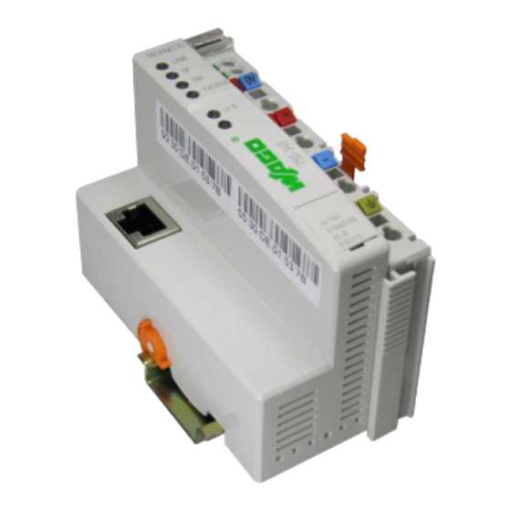
Page 48: Fieldbus Coupler
3.1.1 Description The fieldbus coupler 750-340 maps the peripheral data of almost all I/O modules in the WAGO-I/O-SYSTEM 750/753 on PROFINET IO. In the initialization phase, the fieldbus coupler determines the physical structure of the node and creates a local process image with all inputs and outputs. -
Page 49: Hardware
• Display elements (LEDs) for status display of the operation, the fieldbus communication, the operating voltages as well as for fault messages and diagnostics • Configuration interface • Electronics for communication with the I/O modules (internal bus) and the fieldbus interface WAGO-I/O-SYSTEM 750 PROFINET IO... -
Page 50: Power Supply
Fig. 3.1.2-2: Power supply g034001e The integrated power supply unit provides the required power to the electronics and to the I/O modules. The electrical isolation between the RJ45 Ethernet connector and the electronics is provided by a transformer. WAGO-I/O-SYSTEM 750 PROFINET IO... -
Page 51: Fieldbus Connection
The electrical isolation between the fieldbus interface and the internal electronics is provided by a transformer. The connection point of the coupler is lowered to fit in an 80mm high switch box once connected to the PROFINET connector. WAGO-I/O-SYSTEM 750 PROFINET IO... -
Page 52: Display Elements
Display elements g034002x red /green / The "I/O" LED indicates both the orange internal bus communication and occurring errors. green Status of the operating voltage – system green Status of the operating voltage – power contacts WAGO-I/O-SYSTEM 750 PROFINET IO... -
Page 53: Configuration Interface
PROFINET IO 750-340 • 45 Hardware 3.1.2.5 Configuration Interface The configuration interface is located behind the cover flap. It is used for communicating with WAGO-I/O-CHECK 2 and optionally for updating the device software (firmware). open flap Configuration interface Fig. 3.1.2-5: Configuration interface... -
Page 54: I/O Device Configuration
Further Information The PNO provides information about the GSD files of all listed manufacturers. GSD and symbol files for configuring the WAGO I/O devices can be obtained on CD under the item number 750-916 or on the WAGO INTERNET site. -
Page 55: Configuring Digital I/O Modules
I/O modules having the same type of signal. This is done by configuring the DI_0 modules of the relevant I/O modules. WAGO-I/O-SYSTEM 750 PROFINET IO... - Page 56 (shown with a positive signal in brackets) can be allocated to the signal states of the following digital output I/O modules having the same type of signal. This is done by configuring the DO_0 modules of the relevant I/O modules. WAGO-I/O-SYSTEM 750 PROFINET IO...
- Page 57 I/O modules having the same type of signal. This is done by configuring the DI_0- DI_DIA_0 or DO_DIA_0 modules of the relevant I/O modules. WAGO-I/O-SYSTEM 750 PROFINET IO...
- Page 58 DI_16, DI_DIA_16, DI _8 or DI _8. Care must be taken that the number of previously reserved input bits is sufficient to receive the existing input and diagnostic information of the configured I/O module (represented in brackets with a negative sign). WAGO-I/O-SYSTEM 750 PROFINET IO...
- Page 59 (indicated in brackets with a positive sign) can be allocated to the signal conditions of the following digital I/O modules having the same type of signal. This is done by configuring the Dx0 or Dx_DIA_0 modules of the relevant I/O modules. WAGO-I/O-SYSTEM 750 PROFINET IO...
-
Page 60: Configuring Analog I/O Modules
I/O module during normal operation. Configuration module for analog output 750-550 2AA, 0-10 V modules. Each channel provides 1 word (2 bytes) of data in the output process image of the I/O controller. WAGO-I/O-SYSTEM 750 PROFINET IO... -
Page 61: Configuring Specialty Modules
Configuration module for SSI interface. 1 750-630 1SSI double word (4 bytes) of data are provided in the input process image of the I/O controller. WAGO-I/O-SYSTEM 750 PROFINET IO... -
Page 62: Configuring System Modules
I/O module having the appropriate type of signal or the diagnostics information of diagnostic capable I/O modules. This is done by configuring the DI_0, - DI_DIA_0 DO_DIA_0 or PE_DIA_0 modules for the relevant I/O modules. WAGO-I/O-SYSTEM 750 PROFINET IO... - Page 63 2 bit diagnostic information of the configured I/O module (represented in brackets with a negative sign). DIA_0 The 2 bit diagnostics information are not 750-610 P-Supply, DIA available in the input process image of the I/O controller. WAGO-I/O-SYSTEM 750 PROFINET IO...
-
Page 64: Parameter Setting
Use of the internal data bus extension Internal Data Bus Extension Based upon the settings made in EEPROM setting*) EEPROM that are made using the "WAGO Extension Settings" tool. not used is excluded used is possible Message external The external diagnostics information... - Page 65 Set input image to zero The input information of the respective periphery module is set to zero The input information of the Freeze input image periphery module prevailing before the fault is maintained *) Default settings WAGO-I/O-SYSTEM 750 PROFINET IO...
-
Page 66: Standard Module Parameters
*) Presetting 2) Digital modules whose process data has been allocated to their previous slots implicitly take over the default value strategy of the module on the slot allocated. WAGO-I/O-SYSTEM 750 PROFINET IO... -
Page 67: Fault Safe Module Parameters (F-Parameters)
The F-Target address addresses the F_Dest_Add 1 ... 1022 F-Device The F-Watchdog monitors the data exchange between the F-Host and F- F_WD_Time 1 ... 10000 Device. The settings are carried out in milliseconds. *1) Fixed settings *2) Presettings WAGO-I/O-SYSTEM 750 PROFINET IO... -
Page 68: Channel Parameters
The I/O device receives the device name during configuration (station naming) and saves it permanently. The device name is transferred using Discovery and basic Configuration-Protocol (DCP). The device is activated using the Ethernet address (MAC address). WAGO-I/O-SYSTEM 750 PROFINET IO... -
Page 69: Initialization Phase Of The Fieldbus Coupler
I/O controller. If the coupler upload procedure was not carried out with success then the red I/O LED signals the cause of failure through a flashing cycle. The cause of failures can be obtained in chapter 3.1.9.1. Fig. 3.1.4-6: Initialization phase g012113e WAGO-I/O-SYSTEM 750 PROFINET IO... -
Page 70: Process Image
One of the reasons for this may be the packing of digital I/O modules or the lack of configuration modules for the connected I/O modules during configuration. WAGO-I/O-SYSTEM 750 PROFINET IO... -
Page 71: Allocation Of The Input And Output Data
The process data qualifiers are an integral part of the maximum length of the telegram of 320 bytes and must therefore be considered when mounting the modules. WAGO-I/O-SYSTEM 750 PROFINET IO... -
Page 72: Digital Input Modules
The following table shows a list of the number of bytes for the individual modules that are allocated in the respective process image (PI) and the telegrams (TLG) in the direction of transmission and reception (Tx, Rx). WAGO-I/O-SYSTEM 750 PROFINET IO... - Page 73 Data length / [Byte] Data type Data length / [Byte] Data type Type UINT8 UINT16 UINT32 UINT8 2DI_2DIA UINT16 UINT32 UINT8 UINT8 2DI_2DIA_2ACK UINT16 UINT16 UINT32 UINT32 UINT8 UINT16 UINT32 UINT8 UINT8 UINT8 UINT16 16DI UINT32 WAGO-I/O-SYSTEM 750 PROFINET IO...
-
Page 74: Digital Output Modules
The following table shows a list of the number of bytes for the individual modules that are allocated in the respective process image (PA) and the telegrams (TLG) in the direction of transmission and reception (Tx, Rx). 750-5xx 750-5xx* Module WAGO-I/O-SYSTEM 750 PROFINET IO... - Page 75 2DO_4DIA_PI UINT16 UINT16 UINT32 UINT32 UINT8 UINT16 UINT32 UINT8 4DO_4DIA UINT16 UINT32 UINT8 UINT8 4DO_4DIA_PI UINT16 UINT16 UINT32 UINT32 UINT8 UINT16 UINT32 UINT8 8DO_8DIA UINT16 UINT32 UINT8 UINT8 8DO_8DIA_PI UINT16 UINT16 UINT32 UINT32 UINT16 16DO UINT32 WAGO-I/O-SYSTEM 750 PROFINET IO...
-
Page 76: Analog Input Modules
Data length / [Byte] Data object INST INST Type INT16 INT16 Module 75x-4xx nAE, …, EM Data length / [Byte] Data object Input INST Output INST Type 2AI_EM INT16 INT16 UINT8,UINT8, UINT8,UINT8, 3AI_EM INT16 INT16 4AI_EM UINT8,UINT16 UINT8,UINT16 WAGO-I/O-SYSTEM 750 PROFINET IO... -
Page 77: Analog Output Modules
(TLG) in the direction of transmission and reception (Tx, Rx). Module 75x-4xx nAE, … Data length / [Byte] Data object INST INST Type Module 75x-4xx nAE, … Data length / [Byte] Data object INST INST Type 2AO_EM U8,I16 U8,I16 4AO_EM U8,I16 U8,I16 WAGO-I/O-SYSTEM 750 PROFINET IO... -
Page 78: Specialty Modules
The following table shows a list of the number of bytes for the individual modules that are allocated in the respective process image (PA) and the telegrams (TLG) in the direction of transmission and reception (Tx, Rx). WAGO-I/O-SYSTEM 750 PROFINET IO... - Page 79 Data object INST INST Type Module 75x-404 1CNT / 75x-630 1SSI, EM / 75x-6xx … Data length / [Byte] Data object INST INST Type 1CNT U8,U8,U32 U8,U8,U32 2CNT U8,U16 U8,I16 SSI_EM U8,U8,U32 U8,U8,U32 U8[4] U8[4] U8,U16 U8,U16 WAGO-I/O-SYSTEM 750 PROFINET IO...
-
Page 80: Pulse Width Output Module
(TLG) in the direction of transmission and reception (Tx, Rx). Module 75x-511 2PWM Data length / [Byte] Data object INST INST Type Module 75x-511 2PWM, EM Data length / [Byte] Data object INST INST Type PWM_EM U8,I16 U8,I16 WAGO-I/O-SYSTEM 750 PROFINET IO... -
Page 81: Serial Interfaces And Gateways
(PA) and the telegrams (TLG) in the direction of transmission and reception (Tx, Rx). Module 753-661 4F-DE / 753-662 8F-DE / 75x-667 4F-DE/DA Data length / [Byte] Data object INST INST Type PROFIsafe U8[5] U8[5] WAGO-I/O-SYSTEM 750 PROFINET IO... -
Page 82: System Modules
(PA) and the telegrams (TLG) in the direction of transmission and reception (Tx, Rx). 750-6xx 750-6xx* Module Data length / [Byte] Data type Data length / [Byte] Data type Type 2DIA UINT8 2DIA_PI UINT16 UINT32 WAGO-I/O-SYSTEM 750 PROFINET IO... -
Page 83: Example
A 8.0 (UINT32 OUT) Digital output A 8.1 Digital output A 8.2 Digital output A 8.3 75x-504* 4DA(-4 BIT A) Digital output A 8.4 Digital output A 8.5 Digital output A 8.6 Digital output A 8.7 WAGO-I/O-SYSTEM 750 PROFINET IO... - Page 84 (UINT8 OUT) Digital output A 11.1 Digital output A 11.2 Digital output A 11.3 End module End module * The addresses stated in the table correspond with the process data allocation given in the hardware configuration. WAGO-I/O-SYSTEM 750 PROFINET IO...
-
Page 85: Establishing The Connection
"Configuration and Parameter Setting of the Modules". Note For simplification, only the item numbers are shown as module designation in the table. Therefore, the module "75x-400" corresponds to module "750-400 2 DI/24 V DC/3.0 ms" or "753-400 2 DI/24 V DC/3.0ms" WAGO-I/O-SYSTEM 750 PROFINET IO... -
Page 86: Wago-I/O-System
It describes the version and the length of the following data. An identifier (BlockType)specifies the structure of the diagnosis data. The following identifiers are currently used by the buscoupler: WAGO-I/O-SYSTEM 750 PROFINET IO... -
Page 87: Channel Specific Diagnostics
External errors reported by the subassemblies (e.g. short circuits, line interruptions) are only transmitted to the I/O controller after release when setting the module's parameters. WAGO-I/O-SYSTEM 750 PROFINET IO... -
Page 88: Channel Diagnostics
The fault type (SubStructureDefined) contains the value for channel diagnostics (0x8000). Each fault of a signal channel or sub-module is described in a data set (see ChannelDiagnosisData). The structure of the data set has 6 bytes and is composed of as follows: WAGO-I/O-SYSTEM 750 PROFINET IO... - Page 89 0x0015 Reference point is no longer available 0x0016 Sampling fault 0x0017 Threshold value undershot / overshot 0x0018 Output deactivated 0x0019 Safety relevant fault 0x001A External fault 0x001B Frame fault Cycle time fault 0x00 0x001D Manufacturer specific 0x001E 0x001F Module fault WAGO-I/O-SYSTEM 750 PROFINET IO...
-
Page 90: Fault Types Of I/O Modules With Diagnostics Capability
0x000F / 15 0x0010 / 16 Configuration fault 0x0011 / 17 Transmitter or load voltage missing 0x0012 / 18 Fuse fault 0x0013 / 19 free 0x0014 / 20 Ground fault 0x0015 / 21 Reference channel fault WAGO-I/O-SYSTEM 750 PROFINET IO... - Page 91 Wrong version of the F_parameter set. 0x0047 Invalid CRC of the F-parameter set 0x0048 / 72 Reserved 0x00FF / 255 0x0100 / 256 Internal bus fault 0x0101 / 257 Manufacturer specific 0x7FFF / 32767 0x8000 / 32768 Reserved 0xFFFF / 65535 WAGO-I/O-SYSTEM 750 PROFINET IO...
-
Page 92: Fault Cases Of I/O Modules With Diagnostics Capability
750-476, 750-478, 750-479, 750-480, 750-483, 750-485, 750-492 WORD 750-491 0x03 / 3 Overvoltage 0x07 / 7 Upper limit value Measurement range overflow of the input exceeded signal 0x09 / 9 Fault Internal fault (e.g. hardware fault) WAGO-I/O-SYSTEM 750 PROFINET IO... - Page 93 (continuous short circuit or open circuit), however, no faulty electronic ballasts. OTHER 750-642, 0x07 / 7 Upper limit value The receiver buffer is completely full, there 750-650, exceeded is a danger of loss of data 750-651, 750-653 WAGO-I/O-SYSTEM 750 PROFINET IO...
-
Page 94: Extended Channel Diagnostics
The fault type (UserstructureIdentifier) has the value for the extended channel diagnostics (0x8002). The structure for the data set (see ExtChannelDiagnosisData) has 12 bytes and is composed of as follows: WAGO-I/O-SYSTEM 750 PROFINET IO... - Page 95 The faults described in the following table are faults occurring when configuring both the station substitute (buscoupler) and the modules (I/O modules). Configuration faults are coded using fault type 0x0010 in accordance with the PROFINET IO standard. WAGO-I/O-SYSTEM 750 PROFINET IO...
- Page 96 0xC0018025 The configured data length for the output module is smaller than expected 0x0026 0xC0018026 The configured data length for the output module is larger than expected 0x0027 0xC0018027 The configured data length for the output module is not allowed WAGO-I/O-SYSTEM 750 PROFINET IO...
- Page 97 0xC0018094 The reserved station parameters (Table 0, register 1) have invalid values. 0x0095 0xC0018095 The register access (Table 0, register 1) is not allowed. 0x0096 0xC0018096 The setting of the diagnostics channel (Table 0, register 1) is not allowed. WAGO-I/O-SYSTEM 750 PROFINET IO...
- Page 98 0xC00180B4 The module setting (Table 100, register 75) is not allowed. 0x00B5 0xC00180B5 The reserved station parameter (Table 100, register 76) have invalid values. 0x00B6 0xC00180B6 The reserved station parameter (Table 100, register 77) have invalid values. WAGO-I/O-SYSTEM 750 PROFINET IO...
- Page 99 0x011204xx Internal bus interruption after module slot xx (xx = 0 ... 250). 0x0005 0x011005xx Internal bus initializing fault because of an abortive register communication with the module on slot xx (xx = 1 ... 250). WAGO-I/O-SYSTEM 750 PROFINET IO...
-
Page 100: Difference Between Target And Actual Configuration
0xFFFF 14 / 15 WORD Number of sub-module slots where a difference between the target and actual configuration exists, otherwise 0 The data sets of faulty configured sub-modules are following the data set of one module. WAGO-I/O-SYSTEM 750 PROFINET IO... -
Page 101: Data Set For Identification And Servicing Purposes (I&M 0)
Manufacturer ID WAGO 285 0x37 0x35 WAGO order number 0x30 0x2D filled out with spaces 0x33 0x34 „750-340 “ 0x30 0x20 0x20 0x20 0x20 0x20 0x30 0x30 MAC-ID WAGO filled out with spaces “0030DEKLMNOP ” 0x33 0x30 0x44 0x45 WAGO-I/O-SYSTEM 750 PROFINET IO... -
Page 102: Acyclic Communication Using Record Data Sets
Detailed module faults can be determined via "record data" set 0x0034 (52). The length of the detail diagnostics that must be requested is 2 bytes. The coding of the detail diagnostics is as follows: WAGO-I/O-SYSTEM 750 PROFINET IO... - Page 103 0x0019 Safety relevant fault, a hardware fault has occurred on safety relevant switching parts or there is a program sequence fault caused by the device software. 0x0020 External fault, there is a fault in the detail diagnostics for the input or output periphery. WAGO-I/O-SYSTEM 750 PROFINET IO...
-
Page 104: Led Indication
• After another break, the third blinking sequence starts (approx. 1 Hz). The number of light pulses indicates the Error Argument. 3.1.9.2 Fieldbus Status The upper four LEDs signal the operating status of the PROFIBUS IO communication. WAGO-I/O-SYSTEM 750 PROFINET IO... - Page 105 The buscoupler reports a The data exchange works diagnostics information trouble free. A diagnostic which is still present. information such as cable break on an analog input module is active. * not relevant WAGO-I/O-SYSTEM 750 PROFINET IO...
-
Page 106: Node Status - 'I/O' Led Blinking Code
• The second flash sequence appears after an interval (approx. 1 Hz ). The number of light pulses indicates the Error Code. • After another break, the third blinking sequence starts (approx. 1 Hz). The number of light pulses indicates the Error Argument. WAGO-I/O-SYSTEM 750 PROFINET IO... - Page 107 PROFINET IO 750-340 • 99 LED Indication Fig. 3.1.9-10: Signaling the LED node status g012111e After the error is removed, restart the coupler by turning the power supply off and on again. WAGO-I/O-SYSTEM 750 PROFINET IO...
-
Page 108: I/O' Led Error Messages
Switch off the supply voltage of combination. the node, replace the buscoupler and switch on again. Timeout during serial EEPROM Switch off the supply voltage of access. the node, replace the buscoupler and switch on again. WAGO-I/O-SYSTEM 750 PROFINET IO... - Page 109 Set the clock and hold up the power supply of the buscoupler for at least 15 minutes in order to charge the Goldcap. Maximum number of gateway Reduce the number of modules or mailbox modules correspondent modules to a valid exceeded. number. WAGO-I/O-SYSTEM 750 PROFINET IO...
- Page 110 I/O module is detected. Replace the faulty I/O module. If there is only one I/O module left and the LED blinks, then either this module or the coupler is defective. Replace the faulty component. WAGO-I/O-SYSTEM 750 PROFINET IO...
- Page 111 Interruption of the internal bus Turn off the supply voltage of the behind the nth I/O module with node, replace the (n+1)th I/O process data. module with process data and turn on the supply voltage again. WAGO-I/O-SYSTEM 750 PROFINET IO...
- Page 112 LED blinks four times, thus indicating error code 4 (data error internal bus). After the second break, the third blinking sequence starts. The I/O LED blinks twelve times. Error argument 12 means that the internal bus is interrupted behind the twelfth I/O module. WAGO-I/O-SYSTEM 750 PROFINET IO...
-
Page 113: Status Supply Voltage
Significance Remedy Green System supply O.K. System supply missing Check supply voltage (24 V and 0 V) LED B Significance Remedy Green Field supply O.K. Field supply missing Check supply voltage (24 V and 0 V) WAGO-I/O-SYSTEM 750 PROFINET IO... -
Page 114: Fieldbus Failure
The "I/O" LED flashes red. The buscoupler (I/O device) generates a detailed diagnostic message. When the I/O module fault is repaired, the buscoupler restarts according to the configured restart behavior. The process data is transmitted again and the outputs of the node are set accordingly. WAGO-I/O-SYSTEM 750 PROFINET IO... -
Page 115: Technical Data
Standards and regulations (see chapter 2.2) EMC Immunity to interference acc. to EN 50082-2 (96), EN 61000-6-2 (99) EMC Emission of interference acc. to EN 50082-2 (94) Approvals (see chapter 2.2) (UL508) E175199 Conformity marking WAGO-I/O-SYSTEM 750 PROFINET IO... -
Page 116: Ethernet
The TCP/IP protocol stack offers a high degree of reliability for the transmission of information. In the ETHERNET based (programmable) fieldbus couplers and controllers developed by WAGO, usually various application protocols have been implemented on the basis of the TCP/IP stack. These protocols allow the user to create applications (master applications) with standardized interfaces and transmit process data via an ETHERNET interface. -
Page 117: Network Architecture – Principles And Regulations
Fieldbus Communication • 109 ETHERNET The WAGO ETHERNET TCP/IP fieldbus node does not require any additional master components other than a PC with a network card. So, the fieldbus node can be easily connected to local or global networks using the fieldbus connection. -
Page 118: Transmission Media
For thin coaxial cable, the “2” is rounded up from the 185 meter maximum length for individual thin coaxial segments. The “T” and “F” stand for ‘twisted pair’ and ‘fiber optic’, and simply indicate the cable type. WAGO-I/O-SYSTEM 750 PROFINET IO... - Page 119 • 111 ETHERNET 10Base-T, 100BaseTX Either the 10BaseT standard or 100BaseTX can be used for the WAGO ETHERNET fieldbus node. The network architecture is very easy and inexpensive to assemble with S- UTP cable as transmission medium or with cables of STP type.
-
Page 120: Network Topologies
“data traffic cop” where the hub “polices” the data coming in and going out of the individual ports, so the data will only be transmitted to the required node. WAGO recommends using a switch rather then a hub, this will allow for a more deterministic architecture. - Page 121 It consists of groups of star-configured workstations connected to a linear bus backbone cable. Tree topologies allow for the expansion of an existing network, and enables schools, etc. to configure a network to meet their needs. Fig. 4-5: Tree Topology G012904e WAGO-I/O-SYSTEM 750 PROFINET IO...
- Page 122 Specifications may vary depending on the selected topology, the transmission media and coupler modules used in industrial environments, as well as the use of components from different manufacturers in a network. Therefore, the specifications given here are only intended as recommendations. WAGO-I/O-SYSTEM 750 PROFINET IO...
-
Page 123: Coupler Modules
Matches topology changes and incompatible packet sizes (e.g. used in industrial and office areas). Gateway Links two manufacturer-specific networks which use different software and hardware (i.e., ETHERNET and Interbus-Loop). Tab. 4-2: Comparison of Coupler Modules for Networks WAGO-I/O-SYSTEM 750 PROFINET IO... -
Page 124: Important Terms
Collisions may occur and messages have to be repeatedly transmitted as a result of the large amount of data traffic. The delay time in a Shared ETHERNET cannot be easily calculated or predicted. Fig. 4-6: Principle of Shared ETHERNET G012910e WAGO-I/O-SYSTEM 750 PROFINET IO... - Page 125 The message is then only sent to the node with the correct target address. This reduces the data traffic over the network, extends the bandwidth and prevents collisions. The runtimes can be defined and calculated, making the Switched Ethernet deterministic. Fig. 4-7: Principle of Switched ETHERNET G012909e WAGO-I/O-SYSTEM 750 PROFINET IO...
-
Page 126: Network Communication
The UDP layer is also a transport protocol like TCP, and is arranged above the IP layer. In contrast to the TCP protocol, UDP is not connection oriented. That means there are no monitoring mechanisms for data exchange between sender and receiver. WAGO-I/O-SYSTEM 750 PROFINET IO... - Page 127 EtherNet/IP. Application device profiles (e.g. positioning controllers, semi- conductors, pneumatic valves) CIP application objects library CIP data management services (explicit messages, I/O messages) CIP message routing, connection management Encapsulation protocol TCP, UDP Ethernet (physical interface, CSMA/CD) WAGO-I/O-SYSTEM 750 PROFINET IO...
-
Page 128: Communication Protocols
Fieldbus Communication ETHERNET 4.1.3.2 Communication Protocols In addition to the ETHERNET standard, the following important communication protocols are implemented in the WAGO ETHERNET based (programmable) fieldbus couplers and controllers: • IP Version 4 (Raw-IP and IP-Multicast ) • TCP • UDP •... -
Page 129: Ethernet
The address has a fixed length of 6 Bytes (48 Bit) and contains the address type, the manufacturer’s ID, and the serial number. Examples for the MAC-ID of a WAGO ETHERNET fieldbus coupler (hexadecimal): 00 ETHERNET does not allow addressing of different networks. -
Page 130: Ip-Protocol
The highest bit in Class A networks is always ‘0’. Meaning the highest byte can be in a range of ’0 0000000’ to ‘0 1111111’. Therefore, the address range of a Class A network in the first byte is always between 0 and 127. WAGO-I/O-SYSTEM 750 PROFINET IO... - Page 131 192.000.000.XXX - Ca. 2 million Class C 223.255.255.XXX Each WAGO ETHERNET (programmable) fieldbus coupler or controller can be easily assigned an IP address via the implemented BootP protocol. For small internal networks we recommend selecting a network address from Class C.
- Page 132 • Class C Subnet mask: .255 .255 Depending on the subnet division the subnet masks may, however, contain other values beyond 0 and 255, such as 255.255.255.128 or 255.255.255.248. Your network administrator allocates the subnet mask number to you. WAGO-I/O-SYSTEM 750 PROFINET IO...
- Page 133 IP-Header IP-Data Fig. 4-11: IP Packet The most important information in the IP header is the IP address of the transmitter and the receiver and the transport protocol used. WAGO-I/O-SYSTEM 750 PROFINET IO...
-
Page 134: Raw Ip
The result is known as the acknowledgement number and is returned with the next self-sent packet as an acknowledgement. This ensures that the lost TCP packets are detected and resent, if necessary, in the correct sequence. WAGO-I/O-SYSTEM 750 PROFINET IO... - Page 135 This protocol combines the IP address with the physical MAC address of the respective Ethernet card. It is always used when data transfer to an IP address takes place in the same logical network in which the sender is located. WAGO-I/O-SYSTEM 750 PROFINET IO...
-
Page 136: Administration And Diagnosis Protocols
The dynamic configuration of the IP address via a BootP server offers the user a flexible and simple design of his network. The WAGO BootP server allows any IP address to be easily assigned for the WAGO (programmable) fieldbus coupler or controller. -
Page 137: Http (Hypertext Transfer Protocol)
(e.g. whether IP configuration of the coupler/controller is to be performed via the DHCP protocol, the BootP protocol or from the data stored in the EEPROM). The HTTP server uses port number 80. WAGO-I/O-SYSTEM 750 PROFINET IO... -
Page 138: Dhcp (Dynamic Host Configuration Protocol)
IP address. The time for the renewing should be about one half of the lease time. The rebinding time should be about of the lease time. WAGO-I/O-SYSTEM 750 PROFINET IO... -
Page 139: Dns (Domain Name Systems)
RAM disk. To permanently store the data of the RAM disk, the information is additionally copied into the flash memory. The data is stored in the flash after the file has been closed. Due to the storage process, access times during write cycles are long. WAGO-I/O-SYSTEM 750 PROFINET IO... - Page 140 The TFTP (Trival File Transfer Protocol) is not supported by some of the couplers/controllers. More information You can find a list of the exact available implemented protocols in the chapter "Technical Data" to the fieldbus coupler and/or controller. WAGO-I/O-SYSTEM 750 PROFINET IO...
-
Page 141: Smtp (Simple Mail Transfer Protocol)
Thus the user is able to have a simple access from the respective fieldbus on the fieldbus node. There are based on ETHERNET couplers/controllers available developed by WAGO, with the following possible application protocols: • MODBUS TCP (UDP) •... -
Page 142: Profinet
PROFINET network and the certification of PROFINET devices. Further information The PROFIBUS / PROFINET user organization provides documents that deal with themes concerning PROFIBUS on their INTERNET page: – Technical descriptions WAGO-I/O-SYSTEM 750 PROFINET IO... -
Page 143: Cabling
Fieldbus Communication • 135 PROFINET – Guidelines www.profibus.com 4.2.2 Cabling The guidelines for Ethernet cabling apply to the cabling of the PROFINET network. WAGO-I/O-SYSTEM 750 PROFINET IO... -
Page 144: Overview
(Item-no.: 0888-0412) or on the web pages: www.wago.com Service Download Documentation. More Information Current information on the modular WAGO-I/O-SYSTEM is available in the Internet under: www.wago.com 5.1.1 Digital Input Modules DI DC 5 V 750-414 4 Channel, DC 5 V, 0.2 ms, 2- to 3-conductor connection,... - Page 145 750-425, 753-425 2 Channel, NAMUR, Proximity switch acc. to DIN EN 50227 750-438 2 Channel, NAMUR EEx i, Proximity switch acc. to DIN EN 50227 DI Intruder Detection 750-424, 753-424 2 Channel, DC 24 V, Intruder Detection WAGO-I/O-SYSTEM 750 PROFINET IO...
-
Page 146: Digital Output Modules
2 Channel, AC 230 V, 1 A, isolated outputs, 2 changeover contacts 750-512, 753-512 2 Channel, AC 230 V, DC 30 V, AC/DC 2 A, non-floating, 2 make contacts 750-513, 753-513 2 Channel, AC 230 V, DC 30 V, AC/DC 2 A, isolated outputs, 2 make contacts WAGO-I/O-SYSTEM 750 PROFINET IO... -
Page 147: Analog Intput Modules
2 Channel, DC 0 -30 V,Differential Measurement Input AI Resistance Sensors 750-461, 753-461 2 Channel, Resistance Sensors, PT100 / RTD 750-481/003-000 2 Channel, Resistance Sensors, PT100 / RTD, EEx i 750-460 4 Channel, Resistance Sensors, PT100 / RTD AI Thermocouples WAGO-I/O-SYSTEM 750 PROFINET IO... -
Page 148: Analog Output Modules
2 Channel, DC 0 - 10 V, 10 Bit, 100 mW, 24 V 750-559, 753-559 4 Channel, DC 0 - 10 V AO DC ± 10 V 750-556, 753-556 2 Channel, DC ± 10 V 750-557, 753-557 4 Channel, DC ± 10 V WAGO-I/O-SYSTEM 750 PROFINET IO... -
Page 149: Special Modules
2-Channel Vibration Velocity / Bearing Condition Monitoring VIB I/O PROFIsafe Modules 750-660/000-001 8FDI 24V DC PROFIsafe 750-665/000-001 4FDO 0.5A / 4FDI 24V DC PROFIsafe 750-666/000-001 1FDO 10A / 2FDO 0.5A / 2FDI 24V PROFIsafe RTC Module 750-640 RTC Module WAGO-I/O-SYSTEM 750 PROFINET IO... -
Page 150: System Modules
Field Side Connection Module, AC/DC 0 ... 230 V Separation Modules 750-616 Separation Module 750-621 Separation Module with Power Contacts Binary Spacer Module 750-622 Binary Spacer Module End Module 750-600 End Module, to loop the internal bus WAGO-I/O-SYSTEM 750 PROFINET IO... -
Page 151: Structure Of The Profinet Io Process Data
PROFIBUS IO process image Yes (not possible) 5.2.1.2 2 DI Modules with Diagnostics 750-419, 753-419, 750-421, 753-421, 750-425, 753-425 (1 Bit diagnostics / channel) Process Image Length in [Bit] Diagnostics information in the Input Output PROFIBUS IO process image WAGO-I/O-SYSTEM 750 PROFINET IO... -
Page 152: Di Modules
Diagnostics information in the Input Output PROFIBUS IO process image Yes (not possible) 5.2.1.5 16 DI Modules 750-4xx, 753-4xx Process Image Length in [Bit] Diagnostics information in the Input Output PROFIBUS IO process image Yes (not possible) WAGO-I/O-SYSTEM 750 PROFINET IO... -
Page 153: Digital Output Modules
Process Image Length in [Bit] Diagnostics information in the Input Output PROFIBUS IO process image 750-506, 753-506 (2 bit diagnostics / channel) Process Image Length in [Bit] Diagnostics information in the Input Output PROFIBUS IO process image WAGO-I/O-SYSTEM 750 PROFINET IO... -
Page 154: Do Modules
Output PROFIBUS IO process image Yes (not possible) 5.2.2.6 8 DO Modules with Diagnostics 750-537, 753-537 (1 bit diagnostics / channel) Process Image Length in [Bit] Diagnostics information in the Input Output PROFIBUS IO process image WAGO-I/O-SYSTEM 750 PROFINET IO... -
Page 155: Do Modules
I/O Modules • 147 Structure of the PROFINET IO Process Data 5.2.2.7 16 DO Modules 750-5xx, 753-5xx Process Image Length in [Bit] Diagnostics information in the Input Output PROFIBUS IO process image Yes (not possible) WAGO-I/O-SYSTEM 750 PROFINET IO... -
Page 156: Analog Input Modules
Mapping with access to the register structure Data format MOTOROLA INTEL I/O range Input Output Input Output Channel 0 Channel 1 Mapping without access to the register structure MOTOROLA INTEL Input Output Input Output Channel 0 Channel 1 WAGO-I/O-SYSTEM 750 PROFINET IO... -
Page 157: Ai Modules
Register communication using the Input Output PROFINET IO process image? No (not possible) Mapping with access to the register structure Data format MOTOROLA INTEL I/O range Input Output Input Output Channel 0 Channel 1 Channel 2 WAGO-I/O-SYSTEM 750 PROFINET IO... -
Page 158: Ai Modules
Output Input Output Channel 0 Channel 1 Channel 2 Channel 3 Mapping without access to the register structure Data format MOTOROLA INTEL I/O range Input Output Input Output Channel 0 Channel 1 Channel 2 Channel 3 WAGO-I/O-SYSTEM 750 PROFINET IO... -
Page 159: Analog Output Modules
Mapping with access to the register structure Data format MOTOROLA INTEL I/O range Input Output Input Output Channel 1 Channel 2 Mapping without access to the register structure Data format MOTOROLA INTEL I/O range Input Output Input Output Channel 1 Channel 2 WAGO-I/O-SYSTEM 750 PROFINET IO... -
Page 160: Ao Modules
Output Input Output Channel 1 Channel 2 Channel 3 Channel 4 Mapping without access to the register structure Data format MOTOROLA INTEL I/O range Input Output Input Output Channel 1 Channel 2 Channel 3 Channel 4 WAGO-I/O-SYSTEM 750 PROFINET IO... -
Page 161: Specialty Modules
Process Image Length in [Byte] Register communication using the Input Output PROFINET IO process image? No (not possible) Mapping with access to the register structure Data format MOTOROLA INTEL I/O range Input Output Input Output Channel 0 Channel 1 WAGO-I/O-SYSTEM 750 PROFINET IO... -
Page 162: Pwm Modules
Mapping with access to the register structure Data format MOTOROLA INTEL I/O range Input Output Input Output Channel 0 Channel 1 Mapping without access to the register structure Data format MOTOROLA INTEL I/O range Input Output Input Output Channel 0 Channel 1 WAGO-I/O-SYSTEM 750 PROFINET IO... -
Page 163: Stepper Motor Control
Process Image Length in [Byte] Register communication using the Input Output PROFINET IO process image? No (not possible) Mapping with access to the register structure Data format MOTOROLA INTEL I/O range Input Output Input Output Channel 0 WAGO-I/O-SYSTEM 750 PROFINET IO... -
Page 164: Ssi Transmitter Interface
Mapping with access to the register structure Data format MOTOROLA INTEL I/O range Input Output Input Output Channel 0 Mapping without access to the register structure Data format MOTOROLA INTEL I/O range Input Output Input Output Channel 0 WAGO-I/O-SYSTEM 750 PROFINET IO... -
Page 165: Incremental Encoder Interface
Process Image in [Byte] Register communication using the Input Output PROFINET IO process image? No (not possible) Mapping with access to the register structure Data format MOTOROLA INTEL I/O range Input Output Input Output Channel 0 WAGO-I/O-SYSTEM 750 PROFINET IO... -
Page 166: Serial Interfaces
If bytes D3 and D4 contain data depends on the data width: D3 contains data with cases 4 and 5 byte mode D4 contains data in case 5 byte mode. Bytes D3 and D4 are reserved in 3 byte mode (factory setting) and contain no reference data. WAGO-I/O-SYSTEM 750 PROFINET IO... -
Page 167: Data Exchange Module
Register communication using the Input Output PROFINET IO process image? No (not possible) Mapping with access to the register structure Data format MOTOROLA / INTEL I/O range Input Output Input Output Channel 0 5.2.5.10 ENOCEAN Receiver Module 750-642 WAGO-I/O-SYSTEM 750 PROFINET IO... - Page 168 Process Image in [Byte] Register communication using the Input Output PROFINET IO process image? No (not possible) Mapping with access to the register structure Data format MOTOROLA / INTEL I/O range Input Output Input Output Channel 0 WAGO-I/O-SYSTEM 750 PROFINET IO...
-
Page 169: System Modules
I/O Modules • 161 Structure of the PROFINET IO Process Data 5.2.6 System Modules 5.2.6.1 Supply Modules 750-610, 750-611 (2 bit diagnostics) Process Image Length in [Bit] Diagnostics information in the Input Output PROFIBUS IO process image WAGO-I/O-SYSTEM 750 PROFINET IO... -
Page 170: Configuration And Parameter Setting Of The Modules
(bit fields) in the input process image of the station proxy (fieldbus coupler). One byte process data qualifier (IOPS) is managed in the direction of the I/O controller in the cyclic PROFINET IO telegram for these modules. Parameter Value Significance WAGO-I/O-SYSTEM 750 PROFINET IO... -
Page 171: Wago-I/O-System
One byte process data qualifier (IOPS) is managed in the direction of the I/O controller in the cyclic PROFINET IO telegram for this module. ▪ ▪ ▪ WAGO-I/O-SYSTEM 750 PROFINET IO... - Page 172 Asynchronous diagnostics With external faults, channel diagnostics and the message respective alarms are Channel x (x = 0.1) locked*) • not transferred to the I/O controller • released transferred to the I/O controller *) Default settings WAGO-I/O-SYSTEM 750 PROFINET IO...
-
Page 173: Channel Digital Input Modules
One byte process data qualifier (IOPS) is managed in the direction of the I/O controller in the cyclic PROFINET IO telegram for this module. ▪ ▪ ▪ Parameter Value Significance WAGO-I/O-SYSTEM 750 PROFINET IO... -
Page 174: Channel Digital Input Modules
One byte process data qualifier (IOPS) is managed in the direction of the I/O controller in the cyclic PROFINET IO telegram for this module. ▪ ▪ ▪ Parameter Value Significance WAGO-I/O-SYSTEM 750 PROFINET IO... -
Page 175: Channel Digital Input Modules
One byte process data qualifier (IOPS) is managed in the direction of the I/O controller in the cyclic PROFINET IO telegram for this module. ▪ ▪ ▪ Parameter Value Significance WAGO-I/O-SYSTEM 750 PROFINET IO... -
Page 176: Digital Output Modules
One byte process data qualifier (IOCS) is managed in the direction of the I/O controller in the cyclic PROFINET IO telegram for these modules. ▪ ▪ ▪ WAGO-I/O-SYSTEM 750 PROFINET IO... - Page 177 When configuring the substitute value behavior on the side of the I/O module, these values are transmitted to the binary signal channel with invalid (x = 0.1) output states of the I/O controller. *) Default settings WAGO-I/O-SYSTEM 750 PROFINET IO...
-
Page 178: Channel Digital Output Modules With 1 Bit Diagnostics Status Per Channel
\ - - - - - - - - - - - - - - Input - - - - - - - - - - - - - - / controller in the cyclic PROFINET IO telegram for this module. WAGO-I/O-SYSTEM 750 PROFINET IO... - Page 179 \ - - - - - - - - - - - - - - Input - - - - - - - - - - - - - - / ▪ ▪ ▪ \ - - - - - - - - - - - - - - Input - - - - - - - - - - - - - - / WAGO-I/O-SYSTEM 750 PROFINET IO...
- Page 180 When configuring the substitute value behavior on the side of the I/O module, these values are transmitted to the binary signal channel with invalid (x = 0.1) output states of the I/O controller. *) Default settings WAGO-I/O-SYSTEM 750 PROFINET IO...
-
Page 181: Channel Digital Output Modules With 2 Bit Diagnostics Status Per Channel
\ - - - - - - - - - - - - - - Input - - - - - - - - - - - - - - / controller in the cyclic PROFINET IO telegram for these modules. WAGO-I/O-SYSTEM 750 PROFINET IO... - Page 182 \ - - - - - - - - - - - - - - Input - - - - - - - - - - - - - - / ▪ ▪ ▪ \ - - - - - - - - - - - - - - Input - - - - - - - - - - - - - - / WAGO-I/O-SYSTEM 750 PROFINET IO...
- Page 183 When configuring the substitute value behavior on the side of the I/O module, these values are transmitted to the binary signal channel with invalid (x = 0.1) output states of the I/O controller. *) Default settings WAGO-I/O-SYSTEM 750 PROFINET IO...
-
Page 184: Channel Digital Output Modules
One byte process data qualifier (IOPS) is managed in the direction of the I/O controller in the cyclic PROFINET IO telegram for this module. ▪ ▪ ▪ WAGO-I/O-SYSTEM 750 PROFINET IO... - Page 185 When configuring the substitute value behavior on the side of the I/O module, these values are transmitted to the binary signal channel with invalid (x = 0 ... 3) output states of the I/O controller. *) Default settings WAGO-I/O-SYSTEM 750 PROFINET IO...
-
Page 186: Channel Digital Output Modules With 1 Bit Diagnostics Status Per Channel
\ - - - - - - - - - - - - - - Input - - - - - - - - - - - - - - / controller in the cyclic PROFINET IO telegram for these modules. WAGO-I/O-SYSTEM 750 PROFINET IO... - Page 187 \ - - - - - - - - - - - - - - Input - - - - - - - - - - - - - - / ▪ ▪ ▪ \ - - - - - - - - - - - - - - Input - - - - - - - - - - - - - - / WAGO-I/O-SYSTEM 750 PROFINET IO...
- Page 188 When configuring the substitute value behavior on the side of the I/O module, these values are transmitted to the binary signal channel with invalid (x = 0 ... 3) output states of the I/O controller. *) Default settings WAGO-I/O-SYSTEM 750 PROFINET IO...
-
Page 189: Channel Digital Output Modules
One byte process data qualifier (IOPS) is managed in the transmission direction of the I/O controller in the cyclic PROFINET IO telegram for these modules. ▪ ▪ ▪ WAGO-I/O-SYSTEM 750 PROFINET IO... - Page 190 When configuring the substitute value behavior on the side of the I/O module, these values are transmitted to the binary signal channel with invalid (x = 0 ... 7) output states of the I/O controller. *) Default settings WAGO-I/O-SYSTEM 750 PROFINET IO...
-
Page 191: Channel Digital Output Modules With 1 Bit Diagnostics Status Per Channel
\ - - - - - - - - - - - - - - Input - - - - - - - - - - - - - - / controller in the cyclic PROFINET IO telegram for these modules. WAGO-I/O-SYSTEM 750 PROFINET IO... - Page 192 \ - - - - - - - - - - - - - - Input - - - - - - - - - - - - - - / ▪ ▪ ▪ \ - - - - - - - - - - - - - - Input - - - - - - - - - - - - - - / WAGO-I/O-SYSTEM 750 PROFINET IO...
- Page 193 With the respective configuration of the default value behavior on the side of the I/O module, these values (x = 0 ... 7) are released to binary signal channels with invalid output station of the I/O controller. *) Default settings WAGO-I/O-SYSTEM 750 PROFINET IO...
-
Page 194: Channel Digital Output Modules
One byte process data qualifier (IOPS) is managed in the transmission direction of the I/O controller in the cyclic PROFINET IO telegram for these modules. ▪ ▪ ▪ WAGO-I/O-SYSTEM 750 PROFINET IO... - Page 195 With the respective configuration of the default value behavior on the side of the I/O module, these values (x = 0 ... 15) are released to binary signal channels with invalid output station of the I/O controller. *) Default settings WAGO-I/O-SYSTEM 750 PROFINET IO...
-
Page 196: Channel Digital Input Modules With 1 Bit Diagnostics Status And Confirmation Per Channel
PROFINET IO \ - - - - - - - - - - - - - - Input - - - - - - - - - - - - - - / telegram for these modules. WAGO-I/O-SYSTEM 750 PROFINET IO... - Page 197 \ - - - - - - - - - - - - - - Input - - - - - - - - - - - - - - / transmission direction of the I/O controller in the cyclic PROFINET IO telegram for these modules. WAGO-I/O-SYSTEM 750 PROFINET IO...
- Page 198 \ - - - - - - - - - - - - - - Output - - - - - - - - - - - - - - / ▪ ▪ ▪ \ - - - - - - - - - - - - - - Output - - - - - - - - - - - - - - / WAGO-I/O-SYSTEM 750 PROFINET IO...
- Page 199 Asynchronous diagnostics With external faults, channel diagnostics and the message respective alarms shall be Channel x (x = 0.1) • locked*) not transferred to the I/O Controller released • transferred to the I/O Controller *) Default settings WAGO-I/O-SYSTEM 750 PROFINET IO...
-
Page 200: Analog Input Modules
Register date WR Table 0, HB (LB) \ - - - - - - - - - - - - - - Output - - - - - - - - - - - - - - / WAGO-I/O-SYSTEM 750 PROFINET IO... - Page 201 The process data will be transferred • (x = 0.1) according to the device settings*) using the format settings of the I/O device. • INTEL (LSB-MSB) Little Endian format • MOTOROLA (MSB-LSB) Big Endian format *) Default settings WAGO-I/O-SYSTEM 750 PROFINET IO...
-
Page 202: Channel Analog Input Modules
Input date channel 0, HB (LB) \ - - - - - - - - - - - - - - Input - - - - - - - - - - - - - - / WAGO-I/O-SYSTEM 750 PROFINET IO... - Page 203 Register date WR Table 3, LB (HB) \ - - - - - - - - - - - - - - Output - - - - - - - - - - - - - - / WAGO-I/O-SYSTEM 750 PROFINET IO...
- Page 204 The process data will be transferred • (x = 0 ... 3) according to the device settings*) using the format settings of the I/O device. • INTEL (LSB-MSB) Little Endian format • MOTOROLA (MSB-LSB) Big Endian format *) Default settings WAGO-I/O-SYSTEM 750 PROFINET IO...
-
Page 205: Analog Output Modules
Channel 1 / Table 1, LB4) (HB5)) \ - - - - - - - - - - - - - - Output - - - - - - - - - - - - - - / WAGO-I/O-SYSTEM 750 PROFINET IO... - Page 206 If the switching of substitute values has been selected as a fault strategy, the substitute output (x = 0.1) 0x0000 – 0x7FFF data of the individual output channels can be determined here. 0x0000 – 0xFFFF *) Default settings Existence module dependant WAGO-I/O-SYSTEM 750 PROFINET IO...
-
Page 207: Channel Analog Output Modules
Output date channel 3, LB4 (HB5)) \ - - - - - - - - - - - - - - Output - - - - - - - - - - - - - - / WAGO-I/O-SYSTEM 750 PROFINET IO... - Page 208 Channel 3 / Table 3, LB4) (HB5)) \ - - - - - - - - - - - - - - Output - - - - - - - - - - - - - - / WAGO-I/O-SYSTEM 750 PROFINET IO...
- Page 209 If the switching of substitute values has been selected as a fault strategy, the substitute output (x = 0 ... 3) 0x0000 – 0x7FFF data of the individual output channels can be determined here. 0x0000 – 0xFFFF *) Default settings WAGO-I/O-SYSTEM 750 PROFINET IO...
-
Page 210: Specialty Modules
Byte 04) (Byte 35)) Table 0, LB4) \ - - - - - - - - - - - - - - Output - - - - - - - - - - - - - - / WAGO-I/O-SYSTEM 750 PROFINET IO... - Page 211 The process data will be transferred • (x = 0.1) according to the device settings*) using the format settings of the I/O device. • INTEL (LSB-MSB) Little Endian Format • MOTOROLA (MSB-LSB) Big Endian Format *) Default settings WAGO-I/O-SYSTEM 750 PROFINET IO...
-
Page 212: Pwm Module
LB4) (HB5)) Tab. 1, LB4) (HB5)) \ - - - - - - - - - - - - - - Output - - - - - - - - - - - - - - / WAGO-I/O-SYSTEM 750 PROFINET IO... - Page 213 If the switching of substitute values has been selected as a fault strategy, the substitute output (x = 0.1) 0x0000 – 0x7FFF data of the individual output channels can be determined here. 0x0000 – 0xFFFF *) Default settings WAGO-I/O-SYSTEM 750 PROFINET IO...
-
Page 214: Ssi Transmitter Interface
(Byte 35) ) Table 0, LB4) \ - - - - - - - - - - - - - - Output - - - - - - - - - - - - - - / WAGO-I/O-SYSTEM 750 PROFINET IO... - Page 215 Process data format channel 0 The process data will be transferred • according to the device settings*) using the format settings of the I/O device. • INTEL (LSB-MSB) Little Endian Format • MOTOROLA (MSB-LSB) Big Endian Format *) Default settings WAGO-I/O-SYSTEM 750 PROFINET IO...
-
Page 216: Incremental Encoder Interface
The process data will be transferred • according to the device settings transfer the settings of the I/O device. • INTEL (LSB-MSB) Little Endian Format • MOTOROLA (MSB-LSB) Big Endian Format *) Default settings only with 75x-637 WAGO-I/O-SYSTEM 750 PROFINET IO... -
Page 217: Digital Impulse Interface
Asynchronous diagnostic The following occurs per diagnostics data sets and message diagnostics alarm with external faults channel x • locked*) not transferred to the I/O Controller • released transferred to the I/O Controller *) Default settings WAGO-I/O-SYSTEM 750 PROFINET IO... -
Page 218: Serial Interfaces And Data Exchange Module
The following occurs per diagnostics data sets and message diagnostics alarm when the receiver buffer overfills channel x • locked*) not transferred to the I/O Controller • released transferred to the I/O Controller *) Default settings WAGO-I/O-SYSTEM 750 PROFINET IO... -
Page 219: Enocean Receiver Module
The following occurs per diagnostics data sets and message diagnostics alarm when the receiver buffer overfills channel x locked*) • not transferred to the I/O Controller released • transferred to the I/O Controller *) Default settings WAGO-I/O-SYSTEM 750 PROFINET IO... -
Page 220: Dali/Dsi Master
The following occurs per diagnostics data sets and message diagnostics alarm when the receiver buffer overfills channel x • locked*) not transferred to the I/O Controller • released transferred to the I/O Controller *) Default settings WAGO-I/O-SYSTEM 750 PROFINET IO... -
Page 221: Profisafe Safety Modules
The following occurs per diagnostics data sets and message diagnostics alarm when the receiver buffer overfills channel x locked*) • not transferred to the I/O Controller released • transferred to the I/O Controller *) Default settings WAGO-I/O-SYSTEM 750 PROFINET IO... - Page 222 PROFIsafe address of the F-Host 1 …65534 F_Dest_Add PROFIsafe address of the I/O module (F-Slave) 1 …1022 F_WD_Time Monitoring time of the F Data set in ms 50 ... 100 ... 10000 *) Default settings settings that cannot be modified WAGO-I/O-SYSTEM 750 PROFINET IO...
-
Page 223: Sytem Modules
(bit fields) in the input process image of the station proxy(fieldbus coupler). One byte process data qualifier (IOPS) is managed in the direction of the I/O controller in the cyclic PROFINET IO telegram for these modules. ▪ ▪ ▪ WAGO-I/O-SYSTEM 750 PROFINET IO... - Page 224 Asynchronous diagnostic The following occurs per diagnostics data sets and message diagnostics alarm with external faults channel x • locked*) not transferred to the I/O Controller • released transferred to the I/O Controller *) Default settings WAGO-I/O-SYSTEM 750 PROFINET IO...
-
Page 225: Foreword
This is backed by law, directives or regulations on a national and international scale. WAGO-I/O-SYSTEM 750 (electrical components) is designed for use in zone 2 explosive environments. The following basic explosion protection related terms have been defined. -
Page 226: Explosion Protection Group
For this reason the three sub- groups are assigned representative types of gases: IIA – Propane IIB – Ethylene IIC – Hydrogen Minimal ignition energy of representative types of gases Explosion group Gases Methane Propane Ethylene Hydrogen Ignition energy (µJ) WAGO-I/O-SYSTEM 750 PROFINET IO... -
Page 227: Unit Categories
> 300 °C to 450 °C 200 °C > 200 °C to 300 °C 135 °C > 135 °C to 200 °C 100 °C >100 °C to 135 °C 85°C > 85 °C to 100 °C WAGO-I/O-SYSTEM 750 PROFINET IO... -
Page 228: Types Of Ignition Protection
The standard EN 50 021 allows electrical component manufacturers to obtain certificates from the corresponding authorities for instance KEMA in the Netherlands or the PTB in Germany, certifying that the tested components meet the above mentioned standards draft. WAGO-I/O-SYSTEM 750 PROFINET IO... -
Page 229: Classifications Meeting The Nec 500
Class I (gases and fumes): Group A (Acetylene) Group B (Hydrogen) Group C (Ethylene) Group D (Methane) Class II (dust): Group E (Metal dust) Group F (Coal dust) Group G (Flour, starch and cereal dust) Class III (fibers): No sub-groups WAGO-I/O-SYSTEM 750 PROFINET IO... -
Page 230: Temperature Classes
160 °C >160 °C to 165 °C 135 °C >135 °C to 160 °C 120 °C >120 °C to 135 °C 100 °C >100 °C to 120 °C 85 °C > 85 °C to 100 °C WAGO-I/O-SYSTEM 750 PROFINET IO... -
Page 231: Identification
Hansastr. 27 D-32423 Minden 0.08-2.5mm PATENTS PENDING II 3 G KEMA 01ATEX1024 X EEx nA II T4 Fig. 6.5.1-1: Example for lateral labeling of bus modules (750-400, 2 channel digital input module 24 V DC) g01xx03e WAGO-I/O-SYSTEM 750 PROFINET IO... -
Page 232: For America
Hansastr. 27 D-32423 Minden 0.08-2.5mm PATENTS PENDING II 3 G KEMA 01ATEX1024 X EEx nA II T4 Fig. 6.5.2-1: Example for lateral labeling of bus modules (750-400, 2 channel digital input module 24 V DC) g01xx04e WAGO-I/O-SYSTEM 750 PROFINET IO... -
Page 233: Installation Regulations
DIN VDE 0185 lightning protection systems The USA and Canada have their own regulations. The following are excerpts from these regulations: NFPA 70 National Electrical Code Art. 500 Hazardous Locations ANSI/ISA-RP Recommended Practice 12.6-1987 C22.1 Canadian Electrical Code WAGO-I/O-SYSTEM 750 PROFINET IO... - Page 234 226 • Use in Hazardous Environments Installation regulations Danger When using the WAGO-I/O SYSTEM 750 (electrical operation) with Ex approval, the following points are mandatory: The fieldbus independent I/O System Modules Type 750-xxx are to be installed in enclosures that provide for the degree of ingress protection of at least IP54.
-
Page 235: Index
Fieldbus Failure 106 Star 112 Fieldbus node Transmission Architecture 109 media 110 Firewall 116 rate 108 Gateway 115, 125 speed 110 HTML pages 129 HTTP 129 unlocking lug 19 hub 109, 111, 115, 116 WWW 129 WAGO-I/O-SYSTEM 750 PROFINET IO... - Page 236 WAGO Kontakttechnik GmbH & Co. KG Postfach 2880 • D-32385 Minden Hansastraße 27 • D-32423 Minden Phone: 05 71/8 87 – 0 Fax: 05 71/8 87 – 1 69 E-Mail: info@wago.com Web: http://www.wago.com...
Need help?
Do you have a question about the WAGO-I/O-SYSTEM 750 and is the answer not in the manual?
Questions and answers