
Subscribe to Our Youtube Channel
Related Manuals for WAGO 750-370


Summary of Contents for WAGO 750-370
- Page 1 Modular I/O-System Fieldbus Coupler PROFINET IO 750-370 Manual Technical description, installation and configuration Version 1.0.0...
- Page 2 • Table of Contents Copyright © 2009 by WAGO Kontakttechnik GmbH & Co. KG All rights reserved.. WAGO Kontakttechnik GmbH & Co. KG Hansastraße 27 D-32423 Minden Phone: +49 (0) 571/8 87 – 0 Fax: +49 (0) 571/8 87 – 1 69 E-Mail: info@wago.com...
-
Page 3: Table Of Contents
Safety Information.................. 13 Font Conventions ................... 14 Number Notation..................14 Scope ...................... 14 Abbreviation................... 15 2 The WAGO-I/O-SYSTEM 750 ..............16 System Description................. 16 Technical Data..................17 Manufacturing Number ................23 Component Update................. 24 Storage, Assembly and Transport ............24 Mechanical Setup ................... - Page 4 Shielding (Screening) ................47 2.9.1 General....................47 2.9.2 Bus Conductors.................. 47 2.9.3 Signal Conductors................47 2.9.4 WAGO Shield (Screen) Connecting System........48 2.10 Assembly Guidelines/Standards............. 48 3 Fieldbus Coupler ..................49 PROFINET IO 750-370 ................. 49 3.1.1 Description..................49 3.1.2 Hardware.................... 50 3.1.2.1...
- Page 5 Network Communication..............142 4.1.3.1 Protocol layer model ..............142 4.1.3.2 Communication Protocols............144 4.1.3.2.1 ETHERNET ................145 4.1.3.2.1.1 Channel access method............146 4.1.3.2.2 IP-Protocol ................146 4.1.3.2.2.1 RAW IP ................150 4.1.3.2.2.2 IP Multicast ............... 151 WAGO-I/O-SYSTEM 750 PROFINET IO...
- Page 6 5.2.3.3 4 AI Modules ................178 5.2.4 Analog Output Modules ..............179 5.2.4.1 2 AO Modules................179 5.2.4.2 4 AO Modules................180 5.2.5 Specialty Modules ................181 5.2.5.1 Counter Modules................. 181 5.2.5.2 PWM Modules ................182 WAGO-I/O-SYSTEM 750 PROFINET IO...
- Page 7 PWM Module................232 5.3.5.3 SSI Transmitter Interface............234 5.3.5.4 Incremental Encoder Interface............ 236 5.3.5.5 Digital Impulse Interface ............237 5.3.5.6 Serial Interfaces and Data Exchange Module......238 5.3.5.7 Data Exchange Module............... 239 5.3.5.8 ENOCEAN Receiver Module............. 241 WAGO-I/O-SYSTEM 750 PROFINET IO...
- Page 8 IP Group................... 255 7.1.4 IpRoute table..................256 7.1.5 ICMP Group ..................257 7.1.6 TCP Group..................258 7.1.7 UDP Group ..................259 7.1.8 SNMP Group ................... 259 8 List of Literature ..................261 9 Index ......................262 WAGO-I/O-SYSTEM 750 PROFINET IO...
-
Page 9: Important Notes
Co. KG, Minden, Germany. Non-observance will involve the right to assert damage claims. WAGO Kontakttechnik GmbH & Co. KG reserves the right to provide for any alterations or modifications that serve to increase the efficiency of technical progress. WAGO Kontakttechnik GmbH & Co. KG owns all rights arising from the granting of patents or from the legal protection of utility patents. -
Page 10: Use Of The 750 Series In Compliance With Underlying Provisions
Legal Bases All responsible persons have to familiarize themselves with the underlying legal standards to be applied. WAGO Kontakttechnik GmbH & Co. KG does not assume any liability whatsoever resulting from improper handling and damage incurred to both WAGO´s own and third-party products by disregarding detailed information in this Manual. -
Page 11: Standards And Guidelines For Operating The 750 Series
(emissions of interference) in compliance with EN 61000-6-3. You will find the detailed information in section "WAGO-I/O-SYSTEM 750" ! "System Description" ! "Technical Data". • Please observe the safety precautions against electrostatic discharge in accordance with DIN EN 61340-5-1/-3. -
Page 12: Symbols
Observe the precautionary measure for handling components at risk of electrostatic discharge. Note Make important notes that are to be complied with so that a trouble-free and efficient device operation can be guaranteed. Additional Information References to additional literature, manuals, data sheets and internet pages. WAGO-I/O-SYSTEM 750 PROFINET IO... -
Page 13: Safety Information
Danger The WAGO-I/O-SYSTEM 750 and its components are an open system. It must only be assembled in housings, cabinets or in electrical operation rooms. Access is only permitted via a key or tool to authorized qualified personnel. -
Page 14: Font Conventions
C notation Binary '100' In quotation marks, '0110.0100' nibble separated with dots (.) 1.7 Scope This manual describes the field bus independent WAGO-I/O-SYSTEM 750 with the fieldbus coupler for PROFINET IO. Item-No. Description 750-370 Fieldbus Coupler PROFINET IO WAGO-I/O-SYSTEM 750... -
Page 15: Abbreviation
In this case the Run Time System for the eradication of the user program in the PFC Digital Input Digital Input Module Digital Output Digital Output Module Input/Output Identifier High Byte Low Byte Programmable Logic Controller Software Version WAGO-I/O-SYSTEM 750 PROFINET IO... -
Page 16: The Wago-I/O-System 750
The WAGO-I/O-SYSTEM 750 has a clear port level with LEDs for status indication, insertable mini WSB markers and pullout group marker carriers. The 3-wire technology supplemented by a ground wire connection allows for direct sensor/actuator wiring. -
Page 17: Technical Data
The WAGO-I/O-SYSTEM 750 • 17 Technical Data 2.2 Technical Data Mechanic Material Polycarbonate, Polyamide 6.6 Dimensions W x H* x L * from upper edge of DIN 35 rail - Coupler/Controller (Standard) - 51 mm x 65 mm x 100 mm... - Page 18 18 • The WAGO-I/O-SYSTEM 750 Technical Data Safe electrical isolation Air and creepage distance acc. to IEC 60664-1 Degree of pollution acc. To IEC 61131-2 Degree of protection Degree of protection IP 20 Electromagnetic compatibility Immunity to interference for industrial areas acc. to EN 61000-6-2 (2001)
- Page 19 The WAGO-I/O-SYSTEM 750 • 19 Technical Data Mechanical strength acc. to IEC 61131-2 Test specification Frequency range Limit value 5 Hz ≤ f < 9 Hz IEC 60068-2-6 vibration 1.75 mm amplitude (permanent) 3.5 mm amplitude (short term) 9 Hz ≤ f < 150 Hz 0.5 g (permanent)
- Page 20 20 • The WAGO-I/O-SYSTEM 750 Technical Data For Products of the WAGO-I/O-SYSTEM 750 with ship specific approvals supplementary guidelines are valid: Electromagnetic compatibility Immunity to interference acc. to Germanischer Lloyd (2003) Test specification Test values Strength Evaluation class criteria IEC 61000-4-2 ESD...
- Page 21 In Germany, the Federal Office for Post and Telecommunications and its branch offices issues the permit. It is possible to use other field bus couplers/controllers under certain boundary conditions. Please contact WAGO Kontakttechnik GmbH & Co. KG. Maximum power dissipation of the components Bus modules 0.8 W / bus terminal (total power dissipation,...
- Page 22 22 • The WAGO-I/O-SYSTEM 750 Technical Data Dimensions 01 02 24V 0V Side view Dimensions in mm Fig. 2-2: Dimensions g01xx05e Note The illustration shows a standard coupler. For detailed dimensions, please refer to the technical data of the respective coupler/controller.
-
Page 23: Manufacturing Number
The manufacturing number consists of the production week and year, the software version (if available), the hardware version of the component, the firmware loader (if available) and further internal information for WAGO Kontakttechnik GmbH & Co. KG. WAGO-I/O-SYSTEM 750 PROFINET IO... -
Page 24: Component Update
24 • The WAGO-I/O-SYSTEM 750 Component Update 2.4 Component Update For the case of an Update of one component, the lateral marking on each component contains a prepared matrix. This matrix makes columns available for altogether three updates to the entry of the current update data, like production order number (NO;... -
Page 25: Mechanical Setup
The WAGO-I/O-SYSTEM 750 • 25 Mechanical Setup 2.6 Mechanical Setup 2.6.1 Installation Position Along with horizontal and vertical installation, all other installation positions are allowed. Attention In the case of vertical assembly, an end stop has to be mounted as an additional safeguard against slipping. -
Page 26: Assembly Onto Carrier Rail
WAGO Kontakttechnik GmbH & Co. KG supplies standardized carrier rails that are optimal for use with the I/O system. If other carrier rails are used, then a technical inspection and approval of the rail by WAGO Kontakttechnik GmbH & Co. KG should take place. -
Page 27: Wago Din Rail
The WAGO-I/O-SYSTEM 750 • 27 Mechanical Setup 2.6.3.2 WAGO DIN Rail WAGO carrier rails meet the electrical and mechanical requirements. Item Number Description 210-113 /-112 35 x 7.5; 1 mm; steel yellow chromated; slotted/unslotted 210-114 /-197 35 x 15; 1.5 mm; steel yellow chromated; slotted/unslotted 210-118 35 x 15;... -
Page 28: Plugging And Removal Of The Components
28 • The WAGO-I/O-SYSTEM 750 Mechanical Setup 2.6.5 Plugging and Removal of the Components Warning Before work is done on the components, the voltage supply must be turned off. In order to safeguard the coupler/controller from jamming, it should be fixed onto the carrier rail with the locking disc To do so, push on the upper groove of the locking disc using a screwdriver. -
Page 29: Assembly Sequence
The WAGO-I/O-SYSTEM 750 • 29 Mechanical Setup 2.6.6 Assembly Sequence All system components can be snapped directly on a carrier rail in accordance with the European standard EN 50022 (DIN 35). The reliable positioning and connection is made using a tongue and groove system. -
Page 30: Internal Bus/Data Contacts
30 • The WAGO-I/O-SYSTEM 750 Mechanical Setup 2.6.7 Internal Bus/Data Contacts Communication between the coupler/controller and the bus modules as well as the system supply of the bus modules is carried out via the internal bus. It is comprised of 6 data contacts, which are available as self-cleaning gold spring contacts. -
Page 31: Power Contacts
Fig. 2-8: Example for the arrangement of power contacts g0xxx05e Recommendation With the WAGO ProServe® Software smartDESIGNER, the structure of a field bus node can be configured. The configuration can be tested via the integrated accuracy check. WAGO-I/O-SYSTEM 750... -
Page 32: Wire Connection
More than one conductor per connection is not permissible. If several conductors have to be made at one connection point, then they should be made away from the connection point using WAGO Terminal Blocks. The terminal blocks may be jumpered together and a single wire brought back to the I/O module connection point. -
Page 33: Power Supply
The WAGO-I/O-SYSTEM 750 • 33 Power Supply 2.7 Power Supply 2.7.1 Isolation Within the field bus node, there are three electrically isolated potentials. • Operational voltage for the field bus interface. • Electronics of the couplers/controllers and the bus modules (internal bus). -
Page 34: System Supply
2.7.2 System Supply 2.7.2.1 Connection The WAGO-I/O-SYSTEM 750 requires a 24 V direct current system supply (-15 % or +20 %). The power supply is provided via the coupler/controller and, if necessary, in addition via the internal system supply modules (750-613). -
Page 35: Alignment
The WAGO-I/O-SYSTEM 750 • 35 Power Supply Attention Resetting the system by switching on and off the system supply, must take place simultaneously for all supply modules (coupler/controller and 750-613). 2.7.2.2 Alignment Recommendation A stable network supply cannot be taken for granted always and everywhere. - Page 36 (750-613), e.g. in the middle of the node, should be added. Recommendation With the WAGO ProServe® Software smartDESIGNER, the assembly of a field bus node can be configured. The configuration can be tested via the integrated accuracy check.
-
Page 37: Field Supply
The WAGO-I/O-SYSTEM 750 • 37 Power Supply 2.7.3 Field Supply 2.7.3.1 Connection Sensors and actuators can be directly connected to the relevant channel of the bus module in 1/4 conductor connection technology. The bus module supplies power to the sensors and actuators. The input and output drivers of some bus modules require the field side supply voltage. -
Page 38: Fusing
38 • The WAGO-I/O-SYSTEM 750 Power Supply Attention Some bus modules have no or very few power contacts (depending on the I/O function). Due to this, the passing through of the relevant potential is disrupted. If a field supply is required for subsequent bus modules, then a power supply module must be used. - Page 39 The WAGO-I/O-SYSTEM 750 • 39 Power Supply Warning In the case of power supply modules with fuse holders, only fuses with a maximum dissipation of 1.6 W (IEC 127) must be used. For UL approved systems only use UL approved fuses.
- Page 40 40 • The WAGO-I/O-SYSTEM 750 Power Supply Alternatively, fusing can be done externally. The fuse modules of the WAGO series 281 and 282 are suitable for this purpose. Fig. 2-18: Fuse modules for automotive fuses, series 282 pf66800x Abb. 2-19: Fuse modules for automotive fuses, series 2006 p0xxx13x Fig.
-
Page 41: Supplementary Power Supply Regulations
Power Supply 2.7.4 Supplementary Power Supply Regulations The WAGO-I/O-SYSTEM 750 can also be used in shipbuilding or offshore and onshore areas of work (e. g. working platforms, loading plants). This is demonstrated by complying with the standards of influential classification companies such as Germanischer Lloyd and Lloyds Register. -
Page 42: Supply Example
42 • The WAGO-I/O-SYSTEM 750 Power Supply 2.7.5 Supply Example Attention The system supply and the field supply should be separated in order to ensure bus operation in the event of a short-circuit on the actuator side. 750-400 750-410 750-401... -
Page 43: Power Supply Unit
• 43 Power Supply 2.7.6 Power Supply Unit The WAGO-I/O-SYSTEM 750 requires a 24 V direct current system supply with a maximum deviation of -15 % or +20 %. Recommendation A stable network supply cannot be taken for granted always and everywhere. -
Page 44: Grounding
The optimal insulated setup is a metallic assembly plate with grounding connection with an electrical conductive link with the carrier rail. The separate grounding of the carrier rail can be easily set up with the aid of the WAGO ground wire terminals. Item No. Description... -
Page 45: Grounding Function
The WAGO-I/O-SYSTEM 750 • 45 Grounding 2.8.2 Grounding Function The grounding function increases the resistance against disturbances from electro-magnetic interferences. Some components in the I/O system have a carrier rail contact that dissipates electro-magnetic disturbances to the carrier rail. Fig. 2-24: Carrier rail contact... -
Page 46: Grounding Protection
46 • The WAGO-I/O-SYSTEM 750 Grounding 2.8.3 Grounding Protection For the field side, the ground wire is connected to the lowest connection terminals of the power supply module. The ground connection is then connected to the next module via the Power Jumper Contact (PJC). If the bus... -
Page 47: Shielding (Screening)
Note For a better shield performance, the shield should have previously been placed over a large area. The WAGO shield connection system is suggested for such an application. This suggestion is especially applicable if the equipment can have even current or high impulse formed currents running through (for example initiated by atmospheric discharge). -
Page 48: Wago Shield (Screen) Connecting System
Assembly Guidelines/Standards 2.9.4 WAGO Shield (Screen) Connecting System The WAGO Shield Connecting system includes a shield clamping saddle, a collection of rails and a variety of mounting feet. Together these allow many different possibilities. See catalog W4 volume 3 chapter 10. -
Page 49: Fieldbus Coupler
3 Fieldbus Coupler 3.1 PROFINET IO 750-370 3.1.1 Description The fieldbus coupler 750-370 maps the peripheral data of almost all I/O modules in the WAGO-I/O-SYSTEM 750/753 on PROFINET IO. In the initialization phase, the fieldbus coupler determines the physical structure of the node and creates a local process image with all inputs and outputs. -
Page 50: Profinet Io 750-370
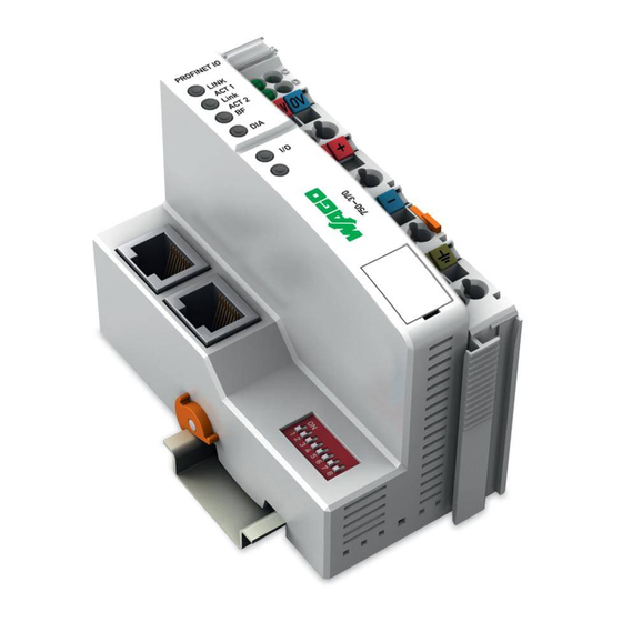
50 • PROFINET IO 750-370 Hardware 3.1.2 Hardware 3.1.2.1 View status PROFINET IO 01 02 voltage supply LINK ACT 1 -power jumper contacts fieldbus LINK -system ACT 2 connection 1 data contacts 24V 0V RJ-45 supply fieldbus connection 2 supply via... -
Page 51: Power Supply
PROFINET IO 750-370 • 51 Hardware 3.1.2.2 Power Supply The power is supplied via terminals with CAGE CLAMP® connection. The power supply provides power to both the system and the field side. 24 V 24 V /0 V 10 nF... -
Page 52: Fieldbus Connection
52 • PROFINET IO 750-370 Hardware 3.1.2.3 Fieldbus Connection The PROFINET IO interface is designed as a RJ-45 connection and complies with 100BaseTX standards. Signal Description TD + Send data + TD - Send data - RD + Receiving data +... -
Page 53: Display Elements
PROFINET IO 750-370 • 53 Hardware 3.1.2.4 Display Elements The operating status of the fieldbus coupler or of the fieldbus node is indicated via light diodes (LEDs). Color Significance green The “LNK/ACT” LEDs indicates that a physical connection to the Ethernet port ACT 1 1 or 2 are etablished. -
Page 54: Configuration Interface
54 • PROFINET IO 750-370 Hardware 3.1.2.5 Configuration Interface The configuration interface is located behind the cover flap. It is used for communicating with WAGO-I/O-CHECK 2 and optionally for updating the device software (firmware). open flap Configuration interface Fig. 3.1.2-5: Configuration interface... -
Page 55: I/O Device Configuration
Further Information The PNO provides information about the GSD files of all listed manufacturers. GSD and symbol files for configuring the WAGO I/O devices can be obtained on CD under the item number 750-916 or on the WAGO INTERNET site. -
Page 56: Configuration
56 • PROFINET IO 750-370 I/O Device Configuration 3.1.3.2 Configuration The I/O device is configured in accordance with the physical arrangement of the node (slot oriented). Module slot 0 contains the fieldbus coupler in its function as station substitute. It does not deliver any process data itself, but provides the parameters required to perform overall settings of the I/O device. - Page 57 PROFINET IO 750-370 • 57 I/O Device Configuration Module Description Name example Configuration module for 32 digital inputs, DI_32 75x-400 2DE(+30 BIT E) 4 bytes are reserved in the input process image of the I/O controller. The bit information in the first byte is allocated to...
- Page 58 58 • PROFINET IO 750-370 I/O Device Configuration Module Description Name example DO_32 Configuration module for 32 digital 75x-504 4DA(+28 BIT A) outputs, 4 bytes are reserved in the output process image of the I/O controller. The bit information in the first byte is allocated to...
- Page 59 PROFINET IO 750-370 • 59 I/O Device Configuration modules of the respective output modules reserve 1, 2 or 4 bytes in the input and output image. Respectively, 1 module of the I/O modules is used to fill previously reserved input and/or output areas. The 2 and 4 byte modules can be found in the hardware catalog under the sub-category “Word / double word...
- Page 60 60 • PROFINET IO 750-370 I/O Device Configuration Module Description Name example DI_DIA_0 Configuration module for filling input 75x-425* 2DE(-4 BIT E), information previously reserved by DIA in E-PA modules DI_32, DI_DIA_32 DI_16, DI_DIA_16, DI _8 or DI _8. Care...
-
Page 61: Configuring Analog I/O Modules
PROFINET IO 750-370 • 61 I/O Device Configuration Module Description Name example Configuration module for 8 digital input DO_DIA_8 75x-507 2DA(+4 BIT A), and outputs, 1 byte is reserved in the output DIA in E-PA and output process image of the I/O controller. - Page 62 62 • PROFINET IO 750-370 I/O Device Configuration Module Description Exemplary Marking AI_EM Configuration module for analog input 75x-467 2AE, 0-10 V, EM modules. Each signal channel provides a structure of 1 byte status and 1 word (2 bytes) of data in the input process image of the I/O controller.
-
Page 63: Configuring Specialty Modules
PROFINET IO 750-370 • 63 I/O Device Configuration 3.1.3.2.3 Configuring Specialty Modules A configuration module is available for configuring all speciality modules such as counter, PWM, encoder and serial interfaces that provides all information of the respective I/O module in the input and output process images. - Page 64 64 • PROFINET IO 750-370 I/O Device Configuration Module Description Exemplary name PE_DIA_32 Configuration module for 32 digital inputs, 750-610 P-Supply, 4 bytes are reserved in the input process 2DIA(+30 BIT E), image of the I/O controller. The bit DIA in E-PA...
-
Page 65: Parameter Setting
PROFINET IO 750-370 • 65 I/O Device Configuration Module Description Exemplary name The 2 bit diagnostics information are not DIA_0 750-610 P- Supply, DIA available in the input process image of the I/O controller. 3.1.3.3 Parameter Setting 3.1.3.3.1 Station Parameters The parameters of the station substitute are used to set the overall settings of the PROFINET IO node. - Page 66 66 • PROFINET IO 750-370 I/O Device Configuration Parameter Setting Description In the case of a malfunction of the Behavior in case of a PROFINET I/O PROFINET IO communication, the fault status of the connected output periphery can be influenced in various ways.
-
Page 67: Standard Module Parameters
PROFINET IO 750-370 • 67 I/O Device Configuration 3.1.3.3.2 Standard Module Parameters Certain characteristics of some I/O modules can be parameterized during the configuration. At present, this only applies to the output modules whose substitute value behavior can be set independent of the modules used. -
Page 68: Fault Safe Module Parameters (F-Parameters)
68 • PROFINET IO 750-370 I/O Device Configuration 3.1.3.3.3 Fault Safe Module Parameters (F-Parameters) Fault safe I/O modules require the standardized PROFIsafe configuration to ensure a safe exchange of productive data. Parameter Setting Description There are no individual parameters F_Check_iPar... -
Page 69: Channel Parameters
PROFINET IO 750-370 • 69 I/O Device Configuration 3.1.3.3.4 Channel Parameters Individual settings of the channel characteristics can be performed when designing several I/O modules. The following channel specific settings can be made depending on the I/O module: Parameter Setting... -
Page 70: Station Naming
In addition to assigning a name via a configuration tool, a device name instance based on the "wago 750 370" or "wago io device" specified strings can be allocated to the device via the DIP switch setting. This kind of station naming is enabled by setting switch 8 to "ON". -
Page 71: Initialization Phase Of The Fieldbus Coupler
PROFINET IO 750-370 • 71 Initialization Phase of the Fieldbus Coupler 3.1.4 Initialization Phase of the Fieldbus Coupler The communication system can be commissioned after the PROFINET IO system has been configured, the I/O devices have been installed and a name has been given to the station. -
Page 72: Process Image
72 • PROFINET IO 750-370 Process Image 3.1.5 Process Image 3.1.5.1 Local Process Image After being switched on, the coupler identifies all I/O modules connected that supply or receive process data (data width or bit width > 0). Note For the number of input and output bits or bytes of the individual I/O modules please refer to the corresponding description of the I/O modules. -
Page 73: Allocation Of The Input And Output Data
PROFINET IO 750-370 • 73 Process Image 3.1.5.2 Allocation of the Input and Output Data The process data is exchanged via the PROFINET IO using the higher ranking controls. A maximum of 320 bytes of output data (including all IOPS and IOCS) can be transferred from the I/O controller to the bus coupler. -
Page 74: Digital Input Modules
74 • PROFINET IO 750-370 Process Image 3.1.5.2.1 Digital Input Modules The group of digital input I/O modules is divided into 8 types of modules: Type of module Description Substitute I/O modules 75x-400, 75x-401, 75x-405, 75x-406, 75x-407, 75x-410, 2-channel digital input module... -
Page 75: Digital Output Modules
PROFINET IO 750-370 • 75 Process Image 750-4xx 750-4xx* Module Data length / [Byte] Data type Data length / [Byte] Data type Type UINT8 UINT16 UINT32 UINT8 2DI_2DIA UINT16 UINT32 UINT8 UINT8 2DI_2DIA_2ACK UINT16 UINT16 UINT32 UINT32 UINT8 UINT16 UINT32... - Page 76 76 • PROFINET IO 750-370 Process Image 8-channel digital output module 1 Bit diagnostic per signal 8DO_8DIA_PI 75x-537 channel, additional diagnostic in the input image 16DO 16-channel digital output module 75x-5xx Digital output modules without diagnostics information in the input process image receive the provider status (IOPS) from the I/O controller and supplies it with the consumer status (IOCS) of existing output information.
- Page 77 PROFINET IO 750-370 • 77 Process Image 75x-5xx 75x-5xx* Module Data length / [Byte] Data type Data length / [Byte] Datea type UINT8 UINT16 UINT32 UINT8 2DO_2DIA UINT16 UINT32 UINT8 UINT8 2DO_2DIA_PI UINT16 UINT16 UINT32 UINT32 UINT8 2DO_4DIA UINT16 UINT32...
-
Page 78: Analog Input Modules
78 • PROFINET IO 750-370 Process Image 3.1.5.2.3 Analog Input Modules The group of analog input modules is divided into 5 types of modules: Type of module Description Substitute I/O modules 2-channel analog input module, 75x-452, 75x-454, 75x-456, 16 Bit input data per signal... -
Page 79: Analog Output Modules
PROFINET IO 750-370 • 79 Process Image 3.1.5.2.4 Analog Output Modules The group of analog output modules is divided into 4 types of modules: Type of module Description Substitute I/O modules 2-channel analog output module, 75x-550, 75x-552, 75x-554, 16 Bit output data per signal... -
Page 80: Specialty Modules
80 • PROFINET IO 750-370 Process Image 3.1.5.2.5 Specialty Modules 3.1.5.2.5.1 Meter and Position Transmitter Interfaces The group of meter and position transmitter interfaces is divided into 5 types of modules: Type of module Description Substitute I/O modules 1 (2)-channel meter module,... - Page 81 PROFINET IO 750-370 • 81 Process Image Module 75x-630 1SSI Data length [Byte] Data object INST INST Type 75x-404 1CNT / 75x-630 1SSI, EM / 75x-6xx … Module Data length [Byte] Data object INST INST Type 1CNT U8,U8,U32 U8,U8,U32 2CNT...
-
Page 82: Pulse Width Output Module
82 • PROFINET IO 750-370 Process Image 3.1.5.2.5.2 Pulse Width Output Module Two module types exist for the PWM output module: Type of module Description Substitute I/O modules 2-Channel PWM output module, 75x-511 16-Bit signed process value per signal channel... -
Page 83: Serial Interfaces And Gateways
PROFINET IO 750-370 • 83 Process Image 3.1.5.2.5.3 Serial Interfaces and Gateways The group of serial interfaces and their gateways is divided into 5 types of modules: Type of module Description Substitute I/O modules Serial interface 75x-650, 75x-651, 75x-653 Data exchange module... -
Page 84: Profisafe I/O Modules
84 • PROFINET IO 750-370 Process Image 3.1.5.2.5.4 PROFIsafe I/O Modules The consumer status (IOPS) of the input or output information is exchanged between the I/O controller and I/O device in both directions with PROFIsafe I/O modules. The following table shows a list of the number of bytes for the individual modules that are allocated in the respective process image (PA) and the telegrams (TLG) in the direction of transmission and reception (Tx, Rx). -
Page 85: Example
PROFINET IO 750-370 • 85 Process Image 3.1.5.3 Example The allocation should become clear by way of a fieldbus node with a coupler and 17 I/O modules. DI DI DI DI DI DI AI AI DO DO DO DO DO DO DO DO... -
Page 86: Wago-I/O-System
86 • PROFINET IO 750-370 Process Image I/O module Module PA I/O Controller * Identifier Inputs Outputs 75x-530* 8DA(-8 BIT A) Digital output A 9.0 Digital output A 9.1 Digital output A 9.2 Digital output A 9.3 Digital output A 9.4 Digital output A 9.5... -
Page 87: Establishing The Connection
PROFINET IO 750-370 • 87 Configuration and Parameter Setting of I/O Modules 3.1.5.4 Establishing the Connection Before starting the productive data exchange between the I/O controller and the I/O device, individual communication instances are created within the PROFINET IO context management and the I/O configuration (target configuration) of the modules is notified. -
Page 88: Diagnostics
88 • PROFINET IO 750-370 Diagnostics 3.1.7 Diagnostics 3.1.7.1 Diagnostics Data Sets The diagnostics information of the buscoupler (I/O device) can be read out acyclically using standard diagnostics data sets (records). The structure of the data sets is defined in the PROFINET IO specification (see IODReadReq or IODReadRes). -
Page 89: Channel Specific Diagnostics
PROFINET IO 750-370 • 89 Diagnostics Identifier Description 0x0010 Channel Diagnostics 0x8104 Deviating set / actual configuration The version enables you to see if the process type (Application Process Identifier – API) follows immediately after the head structure or not. -
Page 90: Channel Diagnostics
90 • PROFINET IO 750-370 Diagnostics The BlockType in the head structure of the data set corresponds to the value for the channel diagnostics (0x0010). The length defines the following diagnostics data for faulty sub-modules or channels. The data for the channel diagnostics is triggered using a general structure (see ChannelDiagnosis or ExtChannelDiagnosis), which is followed by the fault indication of the respective channels. - Page 91 PROFINET IO 750-370 • 91 Diagnostics Byte Data type Description offset Alarm source 0 / 1 WORD Channel 0 … 7 0x0000 ... 0x0 Sub-module 0x8000 BYTE Fault- / Channel type ... 2 reserved Fault type = upcoming fault = 1 ...
-
Page 92: Fault Types Of I/O Modules With Diagnostics Capability
92 • PROFINET IO 750-370 Diagnostics Byte Data type Description offset 0x0020 Reserved 0x003F 0x0040 Wrong F Address of the PROFIsafe I/O module (F-Slave) 0x0041 Invalid F Address of the PROFIsafe I/O module (F-Slave) 0x0042 Wrong F Address of the I/O Controller... - Page 93 PROFINET IO 750-370 • 93 Diagnostics Fault number Significance 0x0016 / 22 Sampling fault 0x0017 / 23 Threshold value undershot / overshot 0x0018 / 24 Output deactivated 0x0019 / 25 Safety relevant fault 0x001A / 26 External fault 0x001B / 27...
-
Page 94: Fault Cases Of I/O Modules With Diagnostics Capability
94 • PROFINET IO 750-370 Diagnostics 3.1.7.2.2 Fault Cases of I/O Modules with Diagnostics Capability Article Data Fault type Significance number format 75x-418, 0x1A / 26 External fault Short circuit of the transmitter power supply 75x-419, 75x-421 75x-425 0x1A / 26... - Page 95 PROFINET IO 750-370 • 95 Diagnostics Article Data Fault type Significance number format WORD 750-553, 0x09 / 9 Fault Output short circuit 750-555, Internal fault (e.g. hardware fault) 750-557, 750-559, 750-560 750-610, 0x11 / 17 Transmitter or load Field voltage too low or not present...
- Page 96 96 • PROFINET IO 750-370 Diagnostics Article Data Fault type Significance number format 750-661, 0x18 / 24 Fault PROFIsafe There is an external fault on and input or 750-662, I/O module output channel. The detailed cause of fault 750-667 can be determined using the record data set of the module (see also documentation on PROFIsafe I/O modules).
-
Page 97: Extended Channel Diagnostics
PROFINET IO 750-370 • 97 Diagnostics 3.1.7.2.2.1 Extended Channel Diagnostics The buscoupler uses the extended channel diagnostics to signal internal bus, configuration and parameter setting faults. According to the PROFINET IO standard, extended fault information must be expressed according to the manufacturer specifications. - Page 98 98 • PROFINET IO 750-370 Diagnostics The following tables describe the possible fault messages that are based on the combination of fault type, extended fault type and additional value. The “xx” symbols used for some additional values represent the signal channel (0x0000 ...
- Page 99 PROFINET IO 750-370 • 99 Diagnostics Fault type “Configuration fault” (0x0010)“ Extended Additional Description fault type value 0x0032 0xC0018032 The bit offset for the output of the module is not allowed. 0x0033 0xC0018033 The bit offset for the diagnostics of the module exceeds the maximum offset.
- Page 100 100 • PROFINET IO 750-370 Diagnostics Fault type “Configuration fault” (0x0010)“ Extended Additional Description fault type value 0x0099 0xC0018099 The reserved station parameters (Table 0, register 3) have invalid values. 0x009A 0xC001809A The connection for creating the process image (Table 0, register 3) is deactivated.
- Page 101 PROFINET IO 750-370 • 101 Diagnostics Missing parameters for both the station substitute (buscoupler) and the modules (I/O modules) are also reported using an extended channel diagnostics. Fault type 0x001F is classified as missing parameters in accordance with the standard.
- Page 102 102 • PROFINET IO 750-370 Diagnostics Invalid module configurations are reported via manufacturer specific fault of type 101 . Additional fault information is available in the following table. Fault type “Configuration fault (0x0101)” Extended Additional Description fault type value 0x0012 0xC0018012 The bit offset for the inputs of the module is not allowed.
-
Page 103: Difference Between Target And Actual Configuration
PROFINET IO 750-370 • 103 Diagnostics 3.1.7.2.3 Difference between Target and Actual Configuration A diagnostics is performed by the coupler when there is a difference between the module configuration of the I/O controller and the number of connected sub-modules (I/O modules). - Page 104 104 • PROFINET IO 750-370 Diagnostics The data sets of faulty configured sub-modules are following the data set of one module. Byte Description Data type offset 14 / 15 WORD 0x00 0x01 Sub-module slot with target and actual deviation 16 / 17...
-
Page 105: Data Set For Identification And Servicing Purposes (I&M 0)
WAGO order number 0x30 0x2D filled out with spaces 0x33 0x37 „750-370 “ 0x30 0x20 0x20 0x20 0x20 0x20 0x30 0x30 MAC-ID WAGO filled out with spaces “0030DEKLMNOP ” 0x33 0x30 0x44 0x45 0xKK 0xLL 0xMM 0xNN 0xOO 0xPP 0x20 0x20 0x20... -
Page 106: Acyclic Communication Using Record Data Sets
106 • PROFINET IO 750-370 Acyclic Communication using Record Data Sets 3.1.8 Acyclic Communication using Record Data Sets In addition to cyclic data communication (PROFIBUS IO standard in compliance with IEC 61158), PROFIBUS IO also offers acyclic communication services as an option. These acyclic services run parallel to cyclic data transfer. - Page 107 0x0020 External fault, there is a fault in the detail diagnostics for the input or output periphery. Notice For the 750-370 Fieldbus Coupler with firmware 03 or later, detail diagnostics must no longer be read via the corresponding dataset. They are directly made available as channel diagnostics.
-
Page 108: Information About The Web-Based Management System (Wbm)
108 • PROFINET IO 750-370 Information about the Web-Based Management System (WBM) 3.1.9 Information about the Web-Based Management System (WBM) HTML pages containing information and setting options are stored in the controller and referred to as the Web-based management system. Access these pages via hyperlinks in the left navigation bar of the browser window. - Page 109 PROFINET IO 750-370 • 109 Information about the Web-Based Management System (WBM) SNMP Click the “SNMP” link to access a Web page in order to specify SNMP settings. This protocol can be used for control and diagnostic information data exchange.
- Page 110 110 • PROFINET IO 750-370 Information about the Web-Based Management System (WBM) Additional information For detailed information about how to set up and configure SNMP, see the section “SNMP Configuration.” Clock Click the “Clock” link to access a Web page in order to perform settings for the controller's internal real-time clock.
- Page 111 PROFINET IO 750-370 • 111 Information about the Web-Based Management System (WBM) Security Click the “Security” link to access a Web page where, using passwords, read and/or write access can be set up for various user groups to prevent configuration changes.
- Page 112 112 • PROFINET IO 750-370 Information about the Web-Based Management System (WBM) Passwords can only be changed by the “admin” user with the appropriate password. A software reset is required changes to take effect. Click the “Software Reset” button to start a software reset of the coupler.
-
Page 113: Snmp Configuration
“MIB objects.” The SNMP of the ETHERNET controller includes both the general MIB according to RFC1213 (MIB II) and a special WAGO MIB. Configuration of this protocol is performed via Web-Based Management (WBM) using the “Snmp” link or directly via SNMP. - Page 114 114 • PROFINET IO 750-370 SNMP configuration Fig. 3.1.10-13: Web-based Management p037001x During “SNMP Configuration,” both the device name (sysName) and device description (sysDescription), as well as location (sysLocation) and contact (sysContact), can be set. In the “SNMP v1/v2c (connection-based)” header, the following can occur: •...
-
Page 115: Mib Ii Description
PROFINET IO 750-370 • 115 SNMP configuration encryption can be activated via “DES.” The “Privacy Key” is used for encrypting with DES. Notifications can be activated in SNMPv3 by selecting “Notification/Trap enable V3”; to do this, the IP address of the notification manager must be entered in “Notification Receiver IP”. -
Page 116: Standard Traps
116 • PROFINET IO 750-370 SNMP configuration 3.1.10.2.1 Standard traps For specific events, the SNMP agent will independently send one of the following messages without polling the manager. However, this function must first be activated via WBM. Traps in version 1 — and notifications in both versions 2c and 3 —... -
Page 117: Led Indication
PROFINET IO LINK ACT1 LINK ACT2 Fig. 3.1.11-14: Indicates 750-370 g037002x The upper four LEDs (LNK/ACT 1, LNK/ACT 2, BF, DIA) indicate the state of the PROFINET IO communication. The lower LED (I/O) displays the internal state of the complete node. -
Page 118: Fieldbus Status
118 • PROFINET IO 750-370 LED Indication 3.1.11.2 Fieldbus Status The upper four LEDs signal the operating status of the PROFIBUS IO communication. Color Significance green LNK/ACT LEDs provide information on each port connection to the ACT 1 PROFINET IO network and identify the station via MAC address (2... -
Page 119: Node Status - 'I/O' Led Blinking Code
PROFINET IO 750-370 • 119 LED Indication 3.1.11.3 Node Status - 'I/O' LED Blinking Code The communication status via internal bus is indicated via the lower “I/O” LED. Significance Remedy Green Fieldbus coupler operates correctly a) At fieldbus coupler start-up:... - Page 120 120 • PROFINET IO 750-370 LED Indication Fig. 3.1.11-15: Signaling the LED node status g012111e After the error is removed, restart the coupler by turning the power supply off and on again. WAGO-I/O-SYSTEM 750 PROFINET IO...
-
Page 121: I/O' Led Error Messages
PROFINET IO 750-370 • 121 LED Indication 3.1.11.4 'I/O' LED Error Messages First blinking sequence: start of error display Second blinking sequence: error code Third blinking sequence: error argument Error code 1: “Hardware and configuration error” Error argument Fault Description... - Page 122 122 • PROFINET IO 750-370 LED Indication Buffer power failure real time Set the clock and hold up the clock (RTC) power supply of the buscoupler for at least 15 minutes in order to charge the Goldcap. Fault during read access to the...
- Page 123 PROFINET IO 750-370 • 123 LED Indication Error code 2 -not used- Fault Argument Fault Description Remedy Not used Error code 3 “Protocol error internal bus” Fault Argument Fault Description Remedy Internal bus communication is If there are passive power supply...
- Page 124 124 • PROFINET IO 750-370 LED Indication Fault code 4 “Physical error internal bus” Fault Argument Faukt Description Remedy Internal bus data transmission Turn off the supply voltage of the error or interruption of the node. Plug one I/O module with internal bus at the buscoupler.
- Page 125 PROFINET IO 750-370 • 125 LED Indication Error code 5 “Initialization error internal bus” Fault Argument Fault Description Remedy Error during register Switch off the supply voltage of communication during internal the node, replace the n-th bus bus initialization. coupler with the process data and switch the power supply back on.
-
Page 126: Status Supply Voltage
126 • PROFINET IO 750-370 LED Indication 3.1.11.5 Status Supply voltage The power supply unit of the coupler has two green LEDs. The link upper LED (A) displays the status of the system supply. The left lower LED (B) reports the status of the field supply. -
Page 127: Error Response
PROFINET IO 750-370 • 127 Error Response 3.1.12 Error Response 3.1.12.1 Fieldbus Failure A fieldbus failure is indicated if the I/O controller switches off or if the Ethernet cable is interrupted. An error in the I/O controller can also lead to a fieldbus failure The red BF LED lights up. -
Page 128: Technical Data
PROFINET I/O specification Twisted Pair S-UTP 100 Ω CAT 5 Transmission medium Buscoupler connection RJ-45 Max. length of fieldbus segment 100 m between switch and 750-370; max. length of network limited by PROFINET I/O specification Baud rate 100 Mbit/s Protocols... -
Page 129: Fieldbus Communication
The TCP/IP protocol stack offers a high degree of reliability for the transmission of information. In the ETHERNET based (programmable) fieldbus couplers and controllers developed by WAGO, usually various application protocols have been implemented on the basis of the TCP/IP stack. These protocols allow the user to create applications (master applications) with standardized interfaces and transmit process data via an ETHERNET interface. - Page 130 130 • Fieldbus Communication ETHERNET The WAGO ETHERNET TCP/IP fieldbus node does not require any additional master components other than a PC with a network card. So, the fieldbus node can be easily connected to local or global networks using the fieldbus connection.
-
Page 131: Network Architecture - Principles And Regulations
Fig. 4-1. Connection Example and Principle of a Fieldbus Node for a Network Architecture 1Netwerkknotene Fieldbus communication between master application and (programmable) fieldbus coupler or controller takes place using the implemented fieldbus specific application protocol, e. g. MODBUS TCP (UDP), EtherNet/IP, BACnet, KNXNET/IP, PROFINET, Powerlink, SERCOS III or others. WAGO-I/O-SYSTEM 750 PROFINET IO... -
Page 132: Transmission Media
For thin coaxial cable, the “2” is rounded up from the 185 meter maximum length for individual thin coaxial segments. The “T” and “F” stand for ‘twisted pair’ and ‘fiber optic’, and simply indicate the cable type. WAGO-I/O-SYSTEM 750 PROFINET IO... - Page 133 “data traffic cop” where the hub “polices” the data coming in and going out of the individual ports, so the data will only be transmitted to the required node. WAGO recommends using a switch rather then a hub, this will allow for a more deterministic architecture.
-
Page 134: Network Topologies
Stations can be added or removed without network interruption. Moreover, in the event of a defective cable, only the network segment and the node connected to this segment is impaired. This considerably increases the fail-safe of the entire network. WAGO-I/O-SYSTEM 750 PROFINET IO... - Page 135 UTP cabling is used. If there is a combination of fiber optic backbone and UTP cabling, the rule is simply translated to 7-6-5 rule. WAGO-I/O-SYSTEM 750 PROFINET IO...
- Page 136 Specifications may vary depending on the selected topology, the transmission media and coupler modules used in industrial environments, as well as the use of components from different manufacturers in a network. Therefore, the specifications given here are only intended as recommendations. WAGO-I/O-SYSTEM 750 PROFINET IO...
-
Page 137: Coupler Modules
Matches topology changes and incompatible packet sizes (e.g. used in industrial and office areas). Gateway Links two manufacturer-specific networks which use different software and hardware (i.e., ETHERNET and Interbus-Loop). Tab. 4-2: Comparison of Coupler Modules for Networks WAGO-I/O-SYSTEM 750 PROFINET IO... -
Page 138: Transmission Mode
ETHERNET 4.1.2.4 Transmission Mode Some ETHERNET based WAGO couplers/controllers support both 10Mbit/s and 100Mbit/s for either full or half duplex operation. To guarantee a safe and fast transmission, both these couplers/controllers and their link partners must be configured for the same transmission mode. -
Page 139: Errors Occurring When Configuring The Transmission Mode
MODBUS/TCP is a master/slave protocol in which the slaves only respond to commands from the master. When only one master is used, data traffic over the network can be controlled and collisions avoided. WAGO-I/O-SYSTEM 750 PROFINET IO... - Page 140 The message is then only sent to the node with the correct target address. This reduces the data traffic over the network, extends the bandwidth and prevents collisions. The runtimes can be defined and calculated, making the Switched ETHERNET deterministic. WAGO-I/O-SYSTEM 750 PROFINET IO...
- Page 141 Fieldbus Communication • 141 ETHERNET Fig. 4-7: Principle of Switched ETHERNET G012909e WAGO-I/O-SYSTEM 750 PROFINET IO...
-
Page 142: Network Communication
The UDP layer is also a transport protocol like TCP, and is arranged above the IP layer. In contrast to the TCP protocol, UDP is not connection oriented. That means there are no monitoring mechanisms for data exchange between sender and receiver. WAGO-I/O-SYSTEM 750 PROFINET IO... - Page 143 EtherNet/IP. Application device profiles (e.g. positioning controllers, semi- conductors, pneumatic valves) CIP application objects library CIP data management services (explicit messages, I/O messages) CIP message routing, connection management Encapsulation protocol TCP, UDP ETHERNET (physical interface, CSMA/CD) WAGO-I/O-SYSTEM 750 PROFINET IO...
-
Page 144: Communication Protocols
Fieldbus Communication ETHERNET 4.1.3.2 Communication Protocols In addition to the ETHERNET standard, the following important communication protocols are implemented in the WAGO ETHERNET based (programmable) fieldbus couplers and controllers: • IP Version 4 (Raw-IP and IP-Multicast ) • TCP • UDP •... -
Page 145: Ethernet
The address has a fixed length of 6 Bytes (48 Bit) and contains the address type, the manufacturer’s ID, and the serial number. Examples for the MAC-ID of a WAGO ETHERNET fieldbus coupler (hexadecimal): 00 ETHERNET does not allow addressing of different networks. -
Page 146: Channel Access Method
ID) and subscriber identification (subscriber ID) of varying lengths. The net ID defines the network in which the subscriber is located. The subscriber ID identifies a particular subscriber within this network. Networks are divided into various network classes for addressing purposes: WAGO-I/O-SYSTEM 750 PROFINET IO... - Page 147 Class C 192.000.000.XXX - Ca. 2 million 223.255.255.XXX Each WAGO ETHERNET (programmable) fieldbus coupler or controller can be easily assigned an IP address via the implemented BootP protocol. For small internal networks we recommend selecting a network address from Class C.
- Page 148 The mask defines the subscriber ID bits used for subnet coding, which denote the ID of the subscriber. The entire IP address range theoretically lies between 0.0.0.0 and 255.255.255.255. Each 0 and 255 from the IP address range are reserved for the subnet mask. WAGO-I/O-SYSTEM 750 PROFINET IO...
- Page 149 10101100 00010000 00000000 00000000 Subnet-ID: 0.0.233.128 00000000 00000000 11101001 10000000 Host-ID: 0.0.0.72 00000000 00000000 00000000 01001000 Attention Specify the network mask defined by the administrator in the same way as the IP address when installing the network protocol. WAGO-I/O-SYSTEM 750 PROFINET IO...
-
Page 150: Raw Ip
However, the connection must beforehand have been configured with a fixed IP address. The advantages of RAW IP are high data transfer rate and good stability. WAGO-I/O-SYSTEM 750 PROFINET IO... -
Page 151: Ip Multicast
The result is known as the acknowledgement number and is returned with the next self-sent packet as an acknowledgement. This ensures that the lost TCP packets are detected and resent, if necessary, in the correct sequence. WAGO-I/O-SYSTEM 750 PROFINET IO... -
Page 152: Udp
This protocol combines the IP address with the physical MAC address of the respective ETHERNET card. It is always used when data transfer to an IP address takes place in the same logical network in which the sender is located. WAGO-I/O-SYSTEM 750 PROFINET IO... -
Page 153: Administration And Diagnosis Protocols
The dynamic configuration of the IP address via a BootP server offers the user a flexible and simple design of his network. The WAGO BootP server allows any IP address to be easily assigned for the WAGO (programmable) fieldbus coupler or controller. - Page 154 EEPROM at the next boot cycle. If there is an error in the stored parameters, a blink code is output via the IO LED and configuration via BootP is automatically switched on. WAGO-I/O-SYSTEM 750 PROFINET IO...
-
Page 155: Http (Hyper Text Transfer Protocol)
Renewing time The Renewing time indicates, starting from when the coupler/controller must worry about the renewal of the leasing time. Rebinding time The Rebinding time indicates, after which time the coupler/controller must have gotten its new address. WAGO-I/O-SYSTEM 750 PROFINET IO... -
Page 156: Dns (Domain Name Systems)
The update time indicates the interval in seconds, in which the Update Time synchronization with the time server is to take place. Enable Time It indicates whether the SNTP Client is to be activated or deactivated. Client WAGO-I/O-SYSTEM 750 PROFINET IO... -
Page 157: Ftp-Server (File Transfer Protocol)
ALLO Reservation of the necessary storage location for the file RNFR Renames file from (with RNTO) RNTO Renames file in (with RNFR) ABOR Stops current function DELE Deletes file Changes directory LIST Gives the directory list WAGO-I/O-SYSTEM 750 PROFINET IO... -
Page 158: Smtp (Simple Mail Transfer Protocol)
Since many desktop computers are switched off at the end of the day, it is impractical to send SMTP mail there. For that reason, in many networks special SMTP hosts are installed in many networks, which are permanently switched on to enable distribution of received mail to the desktop computers. WAGO-I/O-SYSTEM 750 PROFINET IO... -
Page 159: Application Protocols
Thus the user is able to have a simple access from the respective fieldbus on the fieldbus node. There are based on ETHERNET couplers/controllers available developed by WAGO, with the following possible application protocols: • MODBUS TCP (UDP) •... -
Page 160: Profinet
PROFINET. That way, the specific demands of Ethernet networks can be met in industrial environments. A high standard of quality is ensured through inspections conforming to standards carried out within the PROFINET network and the certification of PROFINET devices. WAGO-I/O-SYSTEM 750 PROFINET IO... -
Page 161: Cabling
The PROFIBUS / PROFINET user organization provides documents that deal with themes concerning PROFIBUS on their INTERNET page: – Technical descriptions – Guidelines www.profibus.com 4.2.2 Cabling The guidelines for Ethernet cabling apply to the cabling of the PROFINET network. WAGO-I/O-SYSTEM 750 PROFINET IO... -
Page 162: O Modules
You will find these manuals on CD ROM „ELECTRONICC Tools and Docs“ (Item No.: 0888-0412) or at http://www.wago.com under Documentation. Additional Information Current information on the modular WAGO-I/O-SYSTEM is available at http://www.wago.com. 5.1.1 Digital Input Modules Tab. 5-1: Digital input modules DI DC 5 V 750-414 4 Channel, DC 5 V, 0.2 ms, 2- to 3-conductor connection,... - Page 163 2 Channel, AC 120 V, 2- to 4-conductor connection; high-side switching DI AC 120(230) V 753-440 4 Channel, AC 120(230) V, 2-conductor connection; high-side switching DI AC 230 V 750-405, 753-405 2 Channel, AC 230 V, 2- to 4-conductor connection; high-side switching WAGO-I/O-SYSTEM 750 PROFINET IO...
-
Page 164: Digital Output Modules
8 Channel, DC 24 V, 0.5 A, short-circuit-protected; high-side switching; diagnostics 750-536 8 Channel, DC 24 V, 0.5 A, short-circuit-protected; low-side switching DO AC 120(230) V 753-540 4 Channel, AC 120(230) V, 0.25 A, short-circuit-protected; high-side switching WAGO-I/O-SYSTEM 750 PROFINET IO... -
Page 165: Analog Input Modules
4 Channel, 4 - 20 mA, single-ended AI 0 - 1 A 750-475, 753-475 2-Channel, 0 - 1 A AC/DC, differential input AI 0 - 5 A 750-475/020-000, 2-Channel, 0 - 5 A AC/DC, differential input 753-475/020-000 WAGO-I/O-SYSTEM 750 PROFINET IO... - Page 166 J, K, B, E, N, R, S, T, U 750-469, 753-469 2 Channel, thermocouples, line break detection, sensor types: J, K, B, E, N, R, S, T, U, L AI Others 750-491 1 Channel for resistor bridges (strain gauge) WAGO-I/O-SYSTEM 750 PROFINET IO...
-
Page 167: Analog Output Modules
2 Channel, DC 0 - 10 V, 10 bit, 100 mW, 24 V 750-559, 753-559 4 Channel, DC 0 - 10 V AO DC ± 10 V 750-556, 753-556 2 Channel, DC ± 10 V 750-557, 753-557 4 Channel, DC ± 10 V WAGO-I/O-SYSTEM 750 PROFINET IO... -
Page 168: Special Modules
AS interface master module Radio Receiver Module 750-642 Radio receiver EnOcean MP Bus Master Module 750-643 MP bus (multi point bus) master module Vibration Monitoring 750-645 2 Channel vibration velocity / bearing condition monitoring VIB I/O WAGO-I/O-SYSTEM 750 PROFINET IO... - Page 169 Stepper Controller RS-422 / 24 V / 20 mA 750-671 Stepper Controller 24 V / 1.5 A 750-672 Stepper Controller 70 V / 7.5 A 6IN, 2OUT 750-673 Servo Stepper Controller 70 V / 7.5 A 6IN, 2OUT WAGO-I/O-SYSTEM 750 PROFINET IO...
-
Page 170: System Modules
Field side connection module, AC/DC 0 ... 230 V Separation Modules 750-616 Separation module 750-621 Separation module with power contacts Binary Spacer Module 750-622 Binary spacer module End Module 750-600 End module, to loop the internal bus WAGO-I/O-SYSTEM 750 PROFINET IO... -
Page 171: Structure Of The Profinet Io Process Data
PROFIBUS IO process image Yes (not possible) 5.2.1.2 2 DI Modules with Diagnostics 750-419, 753-419, 750-421, 753-421, 750-425, 753-425 (1 Bit diagnostics / channel) Process Image Length in [Bit] Diagnostics information in the Input Output PROFIBUS IO process image WAGO-I/O-SYSTEM 750 PROFINET IO... -
Page 172: Di Modules
Diagnostics information in the Input Output PROFIBUS IO process image Yes (not possible) 5.2.1.5 16 DI Modules 750-4xx, 753-4xx Process Image Length in [Bit] Diagnostics information in the Input Output PROFIBUS IO process image Yes (not possible) WAGO-I/O-SYSTEM 750 PROFINET IO... -
Page 173: Digital Output Modules
Process Image Length in [Bit] Diagnostics information in the Input Output PROFIBUS IO process image 750-506, 753-506 (2 bit diagnostics / channel) Process Image Length in [Bit] Diagnostics information in the Input Output PROFIBUS IO process image WAGO-I/O-SYSTEM 750 PROFINET IO... -
Page 174: Do Modules
Output PROFIBUS IO process image Yes (not possible) 5.2.2.6 8 DO Modules with Diagnostics 750-537, 753-537 (1 bit diagnostics / channel) Process Image Length in [Bit] Diagnostics information in the Input Output PROFIBUS IO process image WAGO-I/O-SYSTEM 750 PROFINET IO... -
Page 175: Do Modules
I/O Modules • 175 Structure of the PROFINET IO Process Data 5.2.2.7 16 DO Modules 750-5xx, 753-5xx Process Image Length in [Bit] Diagnostics information in the Input Output PROFIBUS IO process image Yes (not possible) WAGO-I/O-SYSTEM 750 PROFINET IO... -
Page 176: Analog Input Modules
Mapping with access to the register structure Data format MOTOROLA INTEL I/O range Input Output Input Output Channel 0 Channel 1 Mapping without access to the register structure MOTOROLA INTEL Input Output Input Output Channel 0 Channel 1 WAGO-I/O-SYSTEM 750 PROFINET IO... -
Page 177: Ai Modules
Register communication using the Input Output PROFINET IO process image? No (not possible) Mapping with access to the register structure Data format MOTOROLA INTEL I/O range Input Output Input Output Channel 0 Channel 1 Channel 2 WAGO-I/O-SYSTEM 750 PROFINET IO... -
Page 178: Ai Modules
Output Input Output Channel 0 Channel 1 Channel 2 Channel 3 Mapping without access to the register structure Data format MOTOROLA INTEL I/O range Input Output Input Output Channel 0 Channel 1 Channel 2 Channel 3 WAGO-I/O-SYSTEM 750 PROFINET IO... -
Page 179: Analog Output Modules
Mapping with access to the register structure Data format MOTOROLA INTEL I/O range Input Output Input Output Channel 1 Channel 2 Mapping without access to the register structure Data format MOTOROLA INTEL I/O range Input Output Input Output Channel 1 Channel 2 WAGO-I/O-SYSTEM 750 PROFINET IO... -
Page 180: Ao Modules
Output Input Output Channel 1 Channel 2 Channel 3 Channel 4 Mapping without access to the register structure Data format MOTOROLA INTEL I/O range Input Output Input Output Channel 1 Channel 2 Channel 3 Channel 4 WAGO-I/O-SYSTEM 750 PROFINET IO... -
Page 181: Specialty Modules
Process Image Length in [Byte] Register communication using the Input Output PROFINET IO process image? No (not possible) Mapping with access to the register structure Data format MOTOROLA INTEL I/O range Input Output Input Output Channel 0 Channel 1 WAGO-I/O-SYSTEM 750 PROFINET IO... -
Page 182: Pwm Modules
Mapping with access to the register structure Data format MOTOROLA INTEL I/O range Input Output Input Output Channel 0 Channel 1 Mapping without access to the register structure Data format MOTOROLA INTEL I/O range Input Output Input Output Channel 0 Channel 1 WAGO-I/O-SYSTEM 750 PROFINET IO... -
Page 183: Wago-I/O-System
Process Image Length in [Byte] Register communication using the Input Output PROFINET IO process image? No (not possible) Mapping with access to the register structure Data format MOTOROLA INTEL I/O range Input Output Input Output Channel 0 WAGO-I/O-SYSTEM 750 PROFINET IO... -
Page 184: Ssi Transmitter Interface
Mapping with access to the register structure Data format MOTOROLA INTEL I/O range Input Output Input Output Channel 0 Mapping without access to the register structure Data format MOTOROLA INTEL I/O range Input Output Input Output Channel 0 WAGO-I/O-SYSTEM 750 PROFINET IO... -
Page 185: Incremental Encoder Interface
Process Image in [Byte] Register communication using the Input Output PROFINET IO process image? No (not possible) Mapping with access to the register structure Data format MOTOROLA INTEL I/O range Input Output Input Output Channel 0 WAGO-I/O-SYSTEM 750 PROFINET IO... -
Page 186: Serial Interfaces
If bytes D3 and D4 contain data depends on the data width: D3 contains data with cases 4 and 5 byte mode D4 contains data in case 5 byte mode. Bytes D3 and D4 are reserved in 3 byte mode (factory setting) and contain no reference data. WAGO-I/O-SYSTEM 750 PROFINET IO... -
Page 187: Data Exchange Module
Mapping with access to the register structure Data format MOTOROLA INTEL I/O range Input Output Input Output Channel 0 Mapping without access to register structure Data format MOTOROLA INTEL I/O range Input Output Input Output Channel 0 WAGO-I/O-SYSTEM 750 PROFINET IO... -
Page 188: Dali/Dsi Master
Process Image in [Byte] Register communication using the Input Output PROFINET IO process image? No (not possible) Mapping with access to the register structure Data format MOTOROLA / INTEL I/O range Input Output Input Output Channel 0 WAGO-I/O-SYSTEM 750 PROFINET IO... -
Page 189: Safety I/O Modules Profisafe
F_D_CRC1 F_H_CRC1 F_H_CRC1 F_H_CRC1 F_D_CRC2 F_H_CRC2 F_H_CRC2 F_H_CRC2 at 753-662/000-002 5.2.7 System Modules 5.2.7.1 Supply Modules 750-610, 750-611 (2 bit diagnostics) Process Image Length in [Bit] Diagnostics information in the Input Output PROFIBUS IO process image WAGO-I/O-SYSTEM 750 PROFINET IO... -
Page 190: Configuration And Parameter Setting Of The Modules
(bit fields) in the input process image of the station proxy (fieldbus coupler). One byte process data qualifier (IOPS) is managed in the direction of the I/O controller in the cyclic PROFINET IO telegram for these modules. Parameter Value Significance WAGO-I/O-SYSTEM 750 PROFINET IO... -
Page 191: Channel Digital Input Modules With 1 Bit Diagnostics Status Per Channel
One byte process data qualifier (IOPS) is managed in the direction of the I/O controller in the cyclic PROFINET IO telegram for this module. ▪ ▪ ▪ WAGO-I/O-SYSTEM 750 PROFINET IO... - Page 192 Asynchronous diagnostics With external faults, channel diagnostics and the message respective alarms are Channel x (x = 0.1) • locked*) not transferred to the I/O controller • released transferred to the I/O controller *) Default settings WAGO-I/O-SYSTEM 750 PROFINET IO...
-
Page 193: Channel Digital Input Modules
One byte process data qualifier (IOPS) is managed in the direction of the I/O controller in the cyclic PROFINET IO telegram for this module. ▪ ▪ ▪ Parameter Value Significance WAGO-I/O-SYSTEM 750 PROFINET IO... -
Page 194: Channel Digital Input Modules
One byte process data qualifier (IOPS) is managed in the direction of the I/O controller in the cyclic PROFINET IO telegram for this module. ▪ ▪ ▪ Parameter Value Significance WAGO-I/O-SYSTEM 750 PROFINET IO... -
Page 195: Channel Digital Input Modules
One byte process data qualifier (IOPS) is managed in the direction of the I/O controller in the cyclic PROFINET IO telegram for this module. ▪ ▪ ▪ Parameter Value Significance WAGO-I/O-SYSTEM 750 PROFINET IO... -
Page 196: Digital Output Modules
One byte process data qualifier (IOCS) is managed in the direction of the I/O controller in the cyclic PROFINET IO telegram for these modules. ▪ ▪ ▪ WAGO-I/O-SYSTEM 750 PROFINET IO... - Page 197 When configuring the substitute value behavior on the side of the I/O module, these values are transmitted to the binary signal channel with invalid (x = 0.1) output states of the I/O controller. *) Default settings WAGO-I/O-SYSTEM 750 PROFINET IO...
-
Page 198: Channel Digital Output Modules With 1 Bit Diagnostics Status Per Channel
\ - - - - - - - - - - - - - - Input - - - - - - - - - - - - - - / controller in the cyclic PROFINET IO telegram for this module. WAGO-I/O-SYSTEM 750 PROFINET IO... - Page 199 \ - - - - - - - - - - - - - - Input - - - - - - - - - - - - - - / ▪ ▪ ▪ \ - - - - - - - - - - - - - - Input - - - - - - - - - - - - - - / WAGO-I/O-SYSTEM 750 PROFINET IO...
- Page 200 When configuring the substitute value behavior on the side of the I/O module, these values are transmitted to the binary signal channel with invalid (x = 0.1) output states of the I/O controller. *) Default settings WAGO-I/O-SYSTEM 750 PROFINET IO...
-
Page 201: Channel Digital Output Modules With 2 Bit Diagnostics Status Per Channel
\ - - - - - - - - - - - - - - Input - - - - - - - - - - - - - - / controller in the cyclic PROFINET IO telegram for these modules. WAGO-I/O-SYSTEM 750 PROFINET IO... - Page 202 \ - - - - - - - - - - - - - - Input - - - - - - - - - - - - - - / ▪ ▪ ▪ \ - - - - - - - - - - - - - - Input - - - - - - - - - - - - - - / WAGO-I/O-SYSTEM 750 PROFINET IO...
- Page 203 When configuring the substitute value behavior on the side of the I/O module, these values are transmitted to the binary signal channel with invalid (x = 0.1) output states of the I/O controller. *) Default settings WAGO-I/O-SYSTEM 750 PROFINET IO...
-
Page 204: Channel Digital Output Modules
One byte process data qualifier (IOPS) is managed in the direction of the I/O controller in the cyclic PROFINET IO telegram for this module. ▪ ▪ ▪ WAGO-I/O-SYSTEM 750 PROFINET IO... - Page 205 When configuring the substitute value behavior on the side of the I/O module, these values are transmitted to the binary signal channel with invalid (x = 0 ... 3) output states of the I/O controller. *) Default settings WAGO-I/O-SYSTEM 750 PROFINET IO...
-
Page 206: Channel Digital Output Modules With 1 Bit Diagnostics Status Per Channel
\ - - - - - - - - - - - - - - Input - - - - - - - - - - - - - - / controller in the cyclic PROFINET IO telegram for these modules. WAGO-I/O-SYSTEM 750 PROFINET IO... - Page 207 \ - - - - - - - - - - - - - - Input - - - - - - - - - - - - - - / ▪ ▪ ▪ \ - - - - - - - - - - - - - - Input - - - - - - - - - - - - - - / WAGO-I/O-SYSTEM 750 PROFINET IO...
- Page 208 When configuring the substitute value behavior on the side of the I/O module, these values are transmitted to the binary signal channel with invalid (x = 0 ... 3) output states of the I/O controller. *) Default settings WAGO-I/O-SYSTEM 750 PROFINET IO...
-
Page 209: Channel Digital Output Modules
One byte process data qualifier (IOPS) is managed in the transmission direction of the I/O controller in the cyclic PROFINET IO telegram for these modules. ▪ ▪ ▪ WAGO-I/O-SYSTEM 750 PROFINET IO... - Page 210 When configuring the substitute value behavior on the side of the I/O module, these values are transmitted to the binary signal channel with invalid (x = 0 ... 7) output states of the I/O controller. *) Default settings WAGO-I/O-SYSTEM 750 PROFINET IO...
-
Page 211: Channel Digital Output Modules With 1 Bit Diagnostics Status Per Channel
\ - - - - - - - - - - - - - - Input - - - - - - - - - - - - - - / controller in the cyclic PROFINET IO telegram for these modules. WAGO-I/O-SYSTEM 750 PROFINET IO... - Page 212 \ - - - - - - - - - - - - - - Input - - - - - - - - - - - - - - / ▪ ▪ ▪ \ - - - - - - - - - - - - - - Input - - - - - - - - - - - - - - / WAGO-I/O-SYSTEM 750 PROFINET IO...
- Page 213 With the respective configuration of the default value behavior on the side of the I/O module, these values (x = 0 ... 7) are released to binary signal channels with invalid output station of the I/O controller. *) Default settings WAGO-I/O-SYSTEM 750 PROFINET IO...
-
Page 214: Channel Digital Output Modules
One byte process data qualifier (IOPS) is managed in the transmission direction of the I/O controller in the cyclic PROFINET IO telegram for these modules. ▪ ▪ ▪ WAGO-I/O-SYSTEM 750 PROFINET IO... - Page 215 With the respective configuration of the default value behavior on the side of the I/O module, these values (x = 0 ... 15) are released to binary signal channels with invalid output station of the I/O controller. *) Default settings WAGO-I/O-SYSTEM 750 PROFINET IO...
-
Page 216: Channel Digital Input Modules With 1 Bit Diagnostics Status And Confirmation Per Channel
PROFINET IO \ - - - - - - - - - - - - - - Input - - - - - - - - - - - - - - / telegram for these modules. WAGO-I/O-SYSTEM 750 PROFINET IO... - Page 217 \ - - - - - - - - - - - - - - Input - - - - - - - - - - - - - - / transmission direction of the I/O controller in the cyclic PROFINET IO telegram for these modules. WAGO-I/O-SYSTEM 750 PROFINET IO...
- Page 218 \ - - - - - - - - - - - - - - Output - - - - - - - - - - - - - - / ▪ ▪ ▪ \ - - - - - - - - - - - - - - Output - - - - - - - - - - - - - - / WAGO-I/O-SYSTEM 750 PROFINET IO...
- Page 219 Asynchronous diagnostics With external faults, channel diagnostics and the message respective alarms shall be Channel x (x = 0.1) • locked*) not transferred to the I/O Controller released • transferred to the I/O Controller *) Default settings WAGO-I/O-SYSTEM 750 PROFINET IO...
-
Page 220: Analog Input Modules
Register date WR Table 0, HB (LB) \ - - - - - - - - - - - - - - Output - - - - - - - - - - - - - - / WAGO-I/O-SYSTEM 750 PROFINET IO... - Page 221 The process data will be transferred • (x = 0.1) according to the device settings*) using the format settings of the I/O device. • INTEL (LSB-MSB) Little Endian format • MOTOROLA (MSB-LSB) Big Endian format *) Default settings WAGO-I/O-SYSTEM 750 PROFINET IO...
-
Page 222: Channel Analog Input Modules
Input date channel 0, HB (LB) \ - - - - - - - - - - - - - - Input - - - - - - - - - - - - - - / WAGO-I/O-SYSTEM 750 PROFINET IO... - Page 223 Register date WR Table 3, LB (HB) \ - - - - - - - - - - - - - - Output - - - - - - - - - - - - - - / WAGO-I/O-SYSTEM 750 PROFINET IO...
- Page 224 The process data will be transferred • (x = 0 ... 3) according to the device settings*) using the format settings of the I/O device. • INTEL (LSB-MSB) Little Endian format • MOTOROLA (MSB-LSB) Big Endian format *) Default settings WAGO-I/O-SYSTEM 750 PROFINET IO...
-
Page 225: Analog Output Modules
Channel 1 / Table 1, LB4) (HB5)) \ - - - - - - - - - - - - - - Output - - - - - - - - - - - - - - / WAGO-I/O-SYSTEM 750 PROFINET IO... - Page 226 If the switching of substitute values has been selected as a fault strategy, the substitute output (x = 0.1) 0x0000 – 0x7FFF data of the individual output channels can be determined here. 0x0000 – 0xFFFF *) Default settings Existence module dependant WAGO-I/O-SYSTEM 750 PROFINET IO...
-
Page 227: Channel Analog Output Modules
Output date channel 3, LB4 (HB5)) \ - - - - - - - - - - - - - - Output - - - - - - - - - - - - - - / WAGO-I/O-SYSTEM 750 PROFINET IO... - Page 228 Channel 3 / Table 3, LB4) (HB5)) \ - - - - - - - - - - - - - - Output - - - - - - - - - - - - - - / WAGO-I/O-SYSTEM 750 PROFINET IO...
- Page 229 If the switching of substitute values has been selected as a fault strategy, the substitute output (x = 0 ... 3) 0x0000 – 0x7FFF data of the individual output channels can be determined here. 0x0000 – 0xFFFF *) Default settings WAGO-I/O-SYSTEM 750 PROFINET IO...
-
Page 230: Specialty Modules
Byte 04) (Byte 35)) Table 0, LB4) \ - - - - - - - - - - - - - - Output - - - - - - - - - - - - - - / WAGO-I/O-SYSTEM 750 PROFINET IO... - Page 231 The process data will be transferred • (x = 0.1) according to the device settings*) using the format settings of the I/O device. • INTEL (LSB-MSB) Little Endian Format • MOTOROLA (MSB-LSB) Big Endian Format *) Default settings WAGO-I/O-SYSTEM 750 PROFINET IO...
-
Page 232: Pwm Module
LB4) (HB5)) Tab. 1, LB4) (HB5)) \ - - - - - - - - - - - - - - Output - - - - - - - - - - - - - - / WAGO-I/O-SYSTEM 750 PROFINET IO... - Page 233 If the switching of substitute values has been selected as a fault strategy, the substitute output (x = 0.1) 0x0000 – 0x7FFF data of the individual output channels can be determined here. 0x0000 – 0xFFFF *) Default settings WAGO-I/O-SYSTEM 750 PROFINET IO...
-
Page 234: Ssi Transmitter Interface
(Byte 35) ) Table 0, LB4) \ - - - - - - - - - - - - - - Output - - - - - - - - - - - - - - / WAGO-I/O-SYSTEM 750 PROFINET IO... - Page 235 Process data format channel 0 The process data will be transferred • according to the device settings*) using the format settings of the I/O device. • INTEL (LSB-MSB) Little Endian Format • MOTOROLA (MSB-LSB) Big Endian Format *) Default settings WAGO-I/O-SYSTEM 750 PROFINET IO...
-
Page 236: Incremental Encoder Interface
The process data will be transferred • according to the device settings transfer the settings of the I/O device. • INTEL (LSB-MSB) Little Endian Format • MOTOROLA (MSB-LSB) Big Endian Format *) Default settings only with 75x-637 WAGO-I/O-SYSTEM 750 PROFINET IO... -
Page 237: Digital Impulse Interface
Asynchronous diagnostic The following occurs per diagnostics data sets and message diagnostics alarm with external faults channel x • locked*) not transferred to the I/O Controller • released transferred to the I/O Controller *) Default settings WAGO-I/O-SYSTEM 750 PROFINET IO... -
Page 238: Serial Interfaces And Data Exchange Module
The following occurs per diagnostics data sets and message diagnostics alarm when the receiver buffer overfills channel x • locked*) not transferred to the I/O Controller • released transferred to the I/O Controller *) Default settings WAGO-I/O-SYSTEM 750 PROFINET IO... -
Page 239: Data Exchange Module
Output data Channel 0 Byte 4 \ - - - - - - - - - - - - - - Output - - - - - - - - - - - - - - / WAGO-I/O-SYSTEM 750 PROFINET IO... - Page 240 Asynchronous diagnostic The following occurs per diagnostics data sets and message diagnostics alarm when the receiver buffer overfills Channel 0 • locked not transferred to the I/O Controller • released transferred to the I/O Controller Default settings WAGO-I/O-SYSTEM 750 PROFINET IO...
-
Page 241: Enocean Receiver Module
The following occurs per diagnostics data sets and message diagnostics alarm when the receiver buffer overfills channel x locked*) • not transferred to the I/O Controller released • transferred to the I/O Controller *) Default settings WAGO-I/O-SYSTEM 750 PROFINET IO... -
Page 242: Wago-I/O-System
The following occurs per diagnostics data sets and message diagnostics alarm when the receiver buffer overfills channel x • locked*) not transferred to the I/O Controller • released transferred to the I/O Controller *) Default settings WAGO-I/O-SYSTEM 750 PROFINET IO... -
Page 243: Profisafe Safety Modules
The following occurs per diagnostics data sets and message diagnostics alarm when the receiver buffer overfills channel x locked*) • not transferred to the I/O Controller released • transferred to the I/O Controller *) Default settings WAGO-I/O-SYSTEM 750 PROFINET IO... - Page 244 PROFIsafe address of the F-Host 1 …65534 F_Dest_Add PROFIsafe address of the I/O module (F-Slave) 1 …1022 F_WD_Time Monitoring time of the F Data set in ms 50 ... 100 ... 10000 *) Default settings settings that cannot be modified WAGO-I/O-SYSTEM 750 PROFINET IO...
-
Page 245: System Modules
(bit fields) in the input process image of the station proxy(fieldbus coupler). One byte process data qualifier (IOPS) is managed in the direction of the I/O controller in the cyclic PROFINET IO telegram for these modules. ▪ ▪ ▪ WAGO-I/O-SYSTEM 750 PROFINET IO... - Page 246 Asynchronous diagnostic The following occurs per diagnostics data sets and message diagnostics alarm with external faults channel x • locked*) not transferred to the I/O Controller • released transferred to the I/O Controller *) Default settings WAGO-I/O-SYSTEM 750 PROFINET IO...
-
Page 247: Use In Hazardous Environments
Use in Hazardous Environments • 247 Identification 6 Use in Hazardous Environments WAGO-I/O-SYSTEM 750 (electrical components) is designed for use in zone 2 explosive environments. The following sections include both the identification of components and the installation regulations to be observed. 6.1 Identification 6.1.1 For Europe according to CENELEC and IEC... -
Page 248: For America According To Nec 500
Tab. 6-2: Description of Printing on Printing on Text Description CL 1 Explosion protection group (condition of use category) DIV 2 Area of application (zone) Grp. ABCD Explosion group (gas group) Op temp. code T4 Temperature class WAGO-I/O-SYSTEM 750 PROFINET IO... -
Page 249: Installation Regulations
Installation Regulations NFPA 70 National Electrical Code Art. 500 Hazardous Locations ANSI/ISA-RP 12.6-1987 Recommended Practice C22.1 Canadian Electrical Code Warning When using the WAGO-I/O SYSTEM 750 (electrical operation) with Ex approval, the following points are mandatory: WAGO-I/O-SYSTEM 750 PROFINET IO... -
Page 250: Ansi/Isa 12.12.01
The switch need not be integrated in the equipment. For devices with Ethernet connectors: ”Only for use in LAN, not for connection to telecommunication circuits.” Warning Use Module 750-642 only with antenna module 758-910. WAGO-I/O-SYSTEM 750 PROFINET IO... -
Page 251: Tüv Nord Ex-I Applications
Installation Regulations 6.2.2 TÜV Nord Ex-i applications For operation in zone 2, the WAGO-I/O-System 750-*** must be mounted in an enclosure that fulfills the requirements of the directive 94/9/EG and the relevant standards EN 60079-0 and EN 60079-15. The fulfillment of these requirements must be certified by an appointed office. -
Page 252: Atex And Iec Ex
M2 locations, the modules have to be installed in suitable ATEX Category M2 certified enclosures according to EN 60079-0: 2006 and EN 60079-1: 2007. The Fieldbus Independent Modules of the WAGO-I/O-System 750-…/….- …. have to be installed in a Pollution Degree 2 environment or better in the end use application for use with an IP54 minimum enclosure. -
Page 253: Appendix
This entry contains a unique value for each interface 1.3.6.1.2.1.2.2.1.2 ifDescr This entry contains the name of the manufacturer, the product name, and the version of the hardware interface: e.g., "WAGO Kontakttechnik GmbH 750-870: Rev 1.0". WAGO-I/O-SYSTEM 750 PROFINET IO... - Page 254 This entry indicates the number of outgoing broad and multicast packets delivered to a higher layer. 1.3.6.1.2.1.2.2.1.19 ifOutDiscards This entry indicates the number of packets that were discarded even though no errors had been detected. WAGO-I/O-SYSTEM 750 PROFINET IO...
-
Page 255: Ip Group
1.3.6.1.2.1.4.17 ipFragOKs Number of IP frames fragmented and passed on 1.3.6.1.2.1.4.18 ipFragFails Number of IP frames that should have been fragmented but could not be, because their don't fragment bit was set in the header. WAGO-I/O-SYSTEM 750 PROFINET IO... -
Page 256: Iproute Table
R/W Number of seconds since then the route was last renewed/examined 1.3.6.1.2.1.4.21.1.11 ipRouteMask R/W This entry contents the subnet mask for this entry 1.3.6.1.2.1.4.21.1.12 ipRouteMetric5 R/W An alternative route to the target system 1.3.6.1.2.1.4.21.1.13 ipRouteInfo R/W A reference to a special MIB WAGO-I/O-SYSTEM 750 PROFINET IO... -
Page 257: Icmp Group
Number of sent ICMP timestamp request messages 1.3.6.1.2.1.5.24 icmpOutTimestampR Number of sent ICMP timestamp reply messages 1.3.6.1.2.1.5.25 icmpOutAddrMasks Number of sent ICMP address mask request messages 1.3.6.1.2.1.5.26 icmpOutAddrMask Number of sent ICMP address mask reply Reps messages WAGO-I/O-SYSTEM 750 PROFINET IO... -
Page 258: Tcp Group
The entry contains the remote IP address of Address the TCP connection. 1.3.6.1.2.1.6.13.1.5 tcpConnRemPort The entry contains the remote port of the TCP connection. 1.3.6.1.2.1.6.14 tcpInErrs Number of received incorrect TCP frames 1.3.6.1.2.1.6.15 tcpOutRsts Number of sent TCP frames with set RST flag WAGO-I/O-SYSTEM 750 PROFINET IO... -
Page 259: Udp Group
Number of received SNMP frames with Vars valid GET or GET-NEXT requests 1.3.6.1.2.1.11.14 snmpInTotalSet Number of received SNMP frames with Vars valid SET requests 1.3.6.1.2.1.11.15 snmpInGetRequests R Number of GET requests received and processed 1.3.6.1.2.1.11.16 snmpInGetNexts Number of GET-NEXT requests received WAGO-I/O-SYSTEM 750 PROFINET IO... - Page 260 Number of GET NEXT requests sent 1.3.6.1.2.1.11.27 snmpOutSet Number of SET requests sent Requests 1.3.6.1.2.1.11.28 snmpOutGet Number of GET responses sent Responses 1.3.6.1.2.1.11.29 snmpOutTraps Number of traps sent 1.3.6.1.2.1.11.30 snmpEnable R/W Authentification failure traps AuthenTraps 1 = on, 2 = off WAGO-I/O-SYSTEM 750 PROFINET IO...
-
Page 261: List Of Literature
List of Literature • 261 8 List of Literature Further Information The PNO provides further documentation for its members on internet. http://www.profibus.com/ WAGO-I/O-SYSTEM 750 PROFINET IO... -
Page 262: Index
Switched ................140 Example ..................85 Segment length ................132 Sequence number................151 Shared ETHERNET..............139 Fieldbus Standard Node ..................131 Cabling..................136 Fieldbus Failure ................127 EN 50173, ISO 11801, TIA 568-A ........136 Firewall..................139 Standardization IEEE 802.3................129 Structured cabling ...............136 WAGO-I/O-SYSTEM 750 PROFINET IO... -
Page 263: Wago-I/O-System
Speed..................132 Switch ................. 130, 137 Switched ETHERNET ............... 140 Unlocking Lug ................28 Update Matrix................24 TCP/IP ..................129 Technical data................17 Topology ............132, 134, 136, 137 WWW (World Wide Web)............155 Star..................134 Transmission WAGO-I/O-SYSTEM 750 PROFINET IO... -
Page 264: Hansastraße
WAGO Kontakttechnik GmbH & Co. KG Postfach 2880 • D-32385 Minden Hansastraße 27 • D-32423 Minden Telefon: 05 71/8 87 – 0 Telefax: 05 71/8 87 – 1 69 E-Mail: info@wago.com Internet: http://www.wago.com...
Need help?
Do you have a question about the 750-370 and is the answer not in the manual?
Questions and answers