Table of Contents
Advertisement
Advertisement
Table of Contents

Related Manuals for Copley Controls Xenus Plus Series


Summary of Contents for Copley Controls Xenus Plus Series
- Page 1 Xenus Plus ™ User Guide 123123 P/N 16-01344 Revision 06 August 30, 2019...
- Page 2 Xenus Plus User Guide 16-01344 Rev 06 This page for notes...
-
Page 3: Table Of Contents
A.1: Sizing a Regen Resistor ................................. 135 B: I T Time Limit Algorithm ................................... 139 B.1: I T Algorithm ................................... 140 Thermal Considerations ................................143 C.1: Operating Temperature and Cooling Configurations ......................144 C.2: Heatsink Mounting Instructions (XEL/XPL/XML) ........................148 Copley Controls... - Page 4 F.1: Drive Model Numbers ................................160 F.2: Accessory Model Numbers ..............................163 F.3: Heatsink Kits ................................... 164 F.4: External Regen Resistor Assemblies ............................. 165 F.5: Edge Filter ....................................165 F.6: Order Example ..................................165 F.7: Copley Standard Regen Resistor Specifications ........................166 Copley Controls...
-
Page 5: About This Manual
This manual describes the operation and installation of the XEL, XE2, XPL, XP2, XML, XM2, 800- 1818, 800-1819 and 800-1887 drives manufactured by Copley Controls. All Xenus Plus products have serial numbers that incorporate the week and year of production into the first 4 digits (WWYY) of the serial number. - Page 6 The complete EC Declarations of Conformity for all products are available on the internet at www.copleycontrols.com. Original Instructions This manual is considered to be “original instructions” as defined in EC Directive 2006/42/EC and the contents have been verified by Copley Controls. Copley Controls...
- Page 7 No part of this document may be reproduced in any form or by any means, electronic or mechanical, including photocopying, without express written permission of Copley Controls. Xenus XEL, XE2, XPL, XP2, XML and XM2 are registered trademarks of Copley Controls. CME is a registered trademark of Copley Controls.
- Page 8 Drive heatsink surfaces can exceed 80C and regen resistor surface can exceed 100C depending on drive use conditions Do not touch drive heatsink during operation and allow it to cool before handling after DANGER power is removed. Failure to heed this warning can cause injury Copley Controls...
- Page 9 Xenus Plus User Guide 16-01344 Rev 06 This page for notes. Copley Controls...
-
Page 10: 1: Introduction
Xenus Plus User Guide 16-01344 Rev 06 CHAPTER 1: I NTRODUCTION This chapter provides an overview of the Copley Controls Xenus Plus drives. Contents include: 1.1: Xenus Plus Family Overview ..............................11 1.2: CME ......................................12 1.3: CML/CMO ....................................13 1.4: Copley Virtual Machine (CVM) .............................. -
Page 11: Xenus Plus Family Overview
Mains input voltage to the drive can range from 100 to 240 Vac, single or three-phase, and 47 to 63 Hz. This allows Xenus Plus the ability to work in the widest possible range of industrial settings. Several models are available, with peak output current ratings of 18 to 40 Amps: Copley Controls... -
Page 12: Cme
All Xenus Plus models are RoHS compliant. 1.2: CME Drive commissioning is fast and simple using Copley Controls CME software. CME communicates with Xenus Plus via an RS-232, CANopen, or EtherCAT link, and all the operations needed to configure the drive are accessible through CME. -
Page 13: Cml/Cmo
Copley’s Indexer 2 is an indexer configured and programmed using the tools built into CME. 1.6: CPL CPL is Copley’s high level programming language for writing custom CVM programs. It expands on the features of Indexer 2 with interrupts and features that are faster and more flexible, including looping and branching capabilities. Copley Controls... -
Page 14: 2: Operational Theory
2.7: Position and Velocity Errors ..............................52 2.8: Inputs XEL/XPL/XML ................................55 2.9: Inputs XE2/XP2/XM2/800-1819 ..............................56 2.10: Outputs, XEL/XPL/XML ................................58 2.11: Outputs, XE2/XP2/XM2/800-1819 ............................58 2.12: Brake Operation ..................................58 2.13: Regen Resistor Theory ................................61 Copley Controls... -
Page 15: Drive Power Architecture
DC brush motor. An internal solid-state switch, together with an external power resistor, provides dissipation during regeneration when the mechanical energy of the motor is converted back into electrical energy. This prevents charging the internal capacitors to an overvoltage condition. Copley Controls... - Page 16 Feedback Power and Decoding circuitry in the Signal GND referenced block. The isolation barriers associated with the general purpose inputs and outputs or the STO or MTO inputs are not shown. Copley Controls...
-
Page 17: Operating Modes
2.2.3: Control Modes and Loops Nesting of Control Loops and Modes Copley Controls drives use up to three nested control loops - current, velocity, and position - to control a motor in three associated operating modes. Control Loops Illustration In position mode, the drive uses all three loops. - Page 18 Xenus Plus User Guide 16-01344 Rev 06 Copley Controls...
- Page 19 Adjusting these values is often referred to as tuning the loop. The loop generates a control signal. This signal can be used as the command signal to another Output control loop or the input to a power drive. Copley Controls...
- Page 20 Note: Although the current limits set by the user may exceed the drive's internal limits, the drive operates using both sets of limits in parallel, and therefore will not exceed its own internal limits regardless of the values programmed. Ramp Rate of change in current command. Copley Controls...
- Page 21 The output of the current loop is a command that sets the duty cycle of the PWM output stage. Auto Tune CME provides a current loop Auto Tune feature, which automatically determines optimal Cp and Ci values for the motor. For more information, see the CME User Guide. Copley Controls...
- Page 22 • The drive’s analog or PWM inputs. • A network command, CAN, or RS-232 Serial. • A CVM control program. • The drive’s internal function generator. In position mode, the velocity command is generated by the position loop. Copley Controls...
- Page 23 For more information, see Following Error Fault Details (p. 53 ). Diagram: Effects of Limits on Velocity Command The following diagram illustrates the effects of the velocity loop limits. Limited Velocity Commanded Velocity Vel Limit Accel Limit Decel Limit Copley Controls...
- Page 24 Quadratic filter allows advanced users to define their own filters incorporating two poles and two zeros. For more information on the velocity loop filters, see the CME User Guide. Velocity Loop Outputs The output of the velocity loop is a current command used as the input to the current loop. Copley Controls...
- Page 25 The only limits in effect will now be the velocity loop velocity limit and the current limits. (Note that leaving the maximum acceleration set to zero will prevent other position modes from operating correctly.) The following diagram summarizes the position loop. Copley Controls...
- Page 26 (Note that in either case, velocity loop feedback comes from the motor encoder or resolver.) For more information, see Position Feedback (p. 17). Position Loop Output The output of the position loop is a velocity command used as the input to the velocity loop. Copley Controls...
- Page 27 Absolute moves will move the shortest distance to arrive at the programmed position. This could be in the positive or negative direction. Moves programmed to a point greater than the wrap value will cause an error. To configure the position wrap feature, see the CME User Guide. Copley Controls...
-
Page 28: Input Command Types
For instance, with a dead band of 100 mV, the drive ignores signals between –100 mV and +100 mV, and treats 101 mV as 1 mV, 200 mV as 100 mV, and so on. Dead Band -100 -200 -200 -100 Input Copley Controls... - Page 29 To use the analog position command as an absolute position command, the drive should be homed every time it is enabled. The Homing sequence may be initiated by CAN, EtherCAT, ASCII serial, or CVM Indexer program commands. Copley Controls...
- Page 30 Failsafe Protection from 0 or 100% Duty Cycle Commands In both formats, the drive can be programmed to interpret 0 or 100% duty cycle as a zero command. This provides a measure of safety in case of a controller failure or a cable break. Copley Controls...
- Page 31 Pulse Input Direction Input Velocity Command The drive can be set to increment position on the rising or falling edge of the signal. Stepping resolution can be programmed for electronic gearing. Copley Controls...
- Page 32 Quadrature Format In quadrature format, A/B quadrature commands from a master encoder (via two inputs) provide velocity and direction commands, as shown below. A Input B Input Velocity Command The ratio can be programmed for electronic gearing. Copley Controls...
-
Page 33: Communication
Interface Description The drive features a three-wire RS-232 port. Control commands can be sent over the RS-232 port using Copley Controls ASCII interface commands. In addition, CME software communicates with the drive (using a binary protocol) over this link for drive commissioning, adjustments, and diagnostics. For RS-232... - Page 34 The controller sends the drive a sequence of points, each of which is a segment of a larger, more complex move, rather than a single index or profile. The drive then uses cubic polynomial interpolation to “connect the dots” so that the motor reaches each point at the specified velocity at the programmed time. Copley Controls...
- Page 35 Use programmed value Program address into flash only. For more information on CAN addressing, see the CME User Guide. For more information on CANopen operations, see the following Copley Controls documents: • CANopen Programmer’s Manual • CML Reference Manual •...
- Page 36 The fixed address and station alias are always available. If the switch-based station alias is used, it is the responsibility of the user to ensure that each drive has a unique station alias. Copley Controls...
- Page 37 PWM switching frequency synchronization among the network connected drives. Note that when the STO or MTO function is active, there is no PWM switching or current at the drive motor outputs. See Safe Torque Off & Motor Torque Off (p. 50). Copley Controls...
-
Page 38: Status Indicators
Invalid configuration. A change of state commanded by the master is not possible or is illegal. Single flash Local error. The slave has initiated a change of state by itself in response to an error. Double flash Watchdog timeout. The EtherCAT sync manager watchdog timer has timed out. Copley Controls... - Page 39 XEL J7 LINK and ACT Indicators: EtherCAT Network Status LINK shows the state of the physical link (network). ACT shows activity on the network. LINK Description (Yellow) (Green) Port open, no activity Flicker Port open, network activity Port closed Copley Controls...
- Page 40 PWM outputs cannot produce current in the motor when STO is active. Red/Solid Transient fault condition. Drive will resume operation when fault is removed. Red/Blinking Latching fault. Operation will not resume until fault is cleared or drive is Reset. Copley Controls...
- Page 41 Meaning ERR (Red) EtherCAT communications are working correctly. Blinking Invalid configuration, general configuration error. Single flash Local error, slave has changed EtherCAT state autonomously. Double flash PDO or EtherCAT watchdog timeout, or an application watchdog timeout has occurred, Copley Controls...
- Page 42 MACRO network detected and has disabled drive. Green MACRO network detected and is trying to enable drive. This condition can occur while the AMP LED shows any of its valid color combinations. Steady red MACRO network errors have been detected. Copley Controls...
- Page 43 MACRO network detected and is trying to enable drive. This condition can occur while the AMP LED shows any of its valid color combinations. This LED must be green for the AMP LED to become green. Steady red MACRO network errors have been detected. Copley Controls...
- Page 44 MTO is active, One or both MTO inputs are de-energized. The drive is hardware & followed by a pause software enabled but the PWM outputs cannot produce current in the motor when MTO is active. Steady red A non-latched fault has occurred. Blinking red A latched fault has occurred. Copley Controls...
- Page 45 ERR LED. In addition, these are turned off when the CAN node ID selector (CAN ADDR) is set to 0. A setting of 0, which is invalid, shuts down most operations on the CAN interface, and the LEDs are shut off to indicate this status. Copley Controls...
- Page 46 Single flash green Stopped ERR (Red) LED: CANopen Physical Layer Status 1 second Warning Limit Single flash red Reached 1 second Double flash red Error Control Event 1 second Triple flash red Sync Error Steady red Bus Off Copley Controls...
- Page 47 State Blinking green Normal transmit/receive data on the network Low-level CAN bus errors: • Bit Error • Stuff Error • CRC Error Blinking red • Form Error • Acknowledgment Error Reference Bosch CAN Specification Version 2.0 for details Copley Controls...
- Page 48 PWM outputs cannot produce current in the motor when STO is active. Red/Solid Transient fault condition. Drive will resume operation when fault is removed. Red/Blinking Latching fault. Operation will not resume until fault is cleared or drive is Reset. Copley Controls...
- Page 49 XP2 J8 ERR Indicator Indicates that errors have occurred on the CANopen drive or network ERR (Red) Meaning Single flash red Warning Limit Reached Double flash red Error Control Event Triple flash red Sync Error Steady red Bus Off Copley Controls...
-
Page 50: Protection
Configure faults as latched unless a specific situation calls for non- latched behavior. When using non-latched faults, be sure to safeguard against DANGER unexpected motion. Failure to heed this warning can cause equipment damage, injury, or death. Copley Controls... - Page 51 Position and Velocity Errors (p. 52). Output to output, output to ground, internal *Short Circuit Detected Short circuit has been removed. PWM bridge fault. ○Over Current (Latched) Output current I T limit has been exceeded. Drive is reset and re-enabled. *Latched by default. Copley Controls...
-
Page 52: Position And Velocity Errors
When the position error exceeds the programmed tracking window value, a status word bit is set. The bit is not reset until the position error remains within the tracking window for the programmed tracking time. A similar method is used to handle velocity errors. For detailed information, see Tracking Window Details (p. 54). Copley Controls... - Page 53 Cycle (disable and then enable) an enable input that is configured as Enables with Clear Faults or Enables with Reset • Access the CME Control Panel and press Clear Faults or Reset • Clear the fault over the CANopen network or serial bus Copley Controls...
- Page 54 The bit is not reset until the error remains within the tracking window for the programmed tracking time. Velocity Tracking Illustration The following diagram illustrates the use of tracking window and time settings in velocity mode. Actual Velocity Limited Velocity ± Tracking Window Tracking Time Tracking Window Output Copley Controls...
-
Page 55: Inputs Xel/Xpl/Xml
The second input [AIN2] is programmable for other functions. The ratio of drive output current or velocity vs. reference input voltage is programmable. Analog input [AIN3] Motemp is for use with a motor over temperature switch or sensor connected on J10. Copley Controls... -
Page 56: Inputs Xe2/Xp2/Xm2/800-1818/800-1819/800-1887
CANopen homing operations. Diagram: Sample Placement of Limit Switches The following diagram shows these limit switches in use on a sample motion stage. Mechanical Limits of Motion Stage Home Negative Positive Sw itch Limit Limit Sw itch Sw itch Copley Controls... - Page 57 Two programmable differential analog inputs, AIN1 and AIN2 are connected on J12. As reference inputs they can take position/velocity/torque commands from a controller. If not used as command inputs, they can be used as general-purpose analog inputs. The input voltage range is ±10V. Copley Controls...
-
Page 58: Outputs, Xel/Xpl/Xml
+24 Vdc input. By eliminating the need to connect into the drive control connector, having the brake output on the +24 Vdc power connector simplifies wiring when the brake wires are in the power cable of the motor. Copley Controls... - Page 59 This sequence is not available in the current mode of operation. Instead, in current mode, the drive output turns off and the brake output activates immediately when the disable command is received. Copley Controls...
- Page 60 When the value is negative, the brake is released immediately when the drive is enabled and the PWM outputs are enabled after the programmable delay expires. The graphic below is not part of CME2, but shows the timings in the same colors as the Brake setting screen. Copley Controls...
-
Page 61: Regen Resistor Theory
Regen Circuit Components The drive provides an internal transistor that is used in combination with an external resistor. Copley Controls supplies compatible resistors as described in Regen Resistor Assemblies (p. 165). When using a resistor acquired from another source, be sure it meets the specifications described in Regen Resistor Sizing and Specification (p. - Page 62 Regen Time = 1.25 sec Dwell Time = 1.60 sec Cycle Time = 2.85 sec Internal Regen Resistor Ratings Max Energy 100 W·s (J) Resistance 18 W Power, continuous 20 W Power, peak 70 W Time 2000 ms Copley Controls...
- Page 63 Regen Circuit Components All Xenus Plus drive models provide an internal transistor that can be used in combination with an external resistor. Copley Controls supplies compatible resistors as described in Regen Resistor Assemblies (p. 165). When using a resistor acquired from another source, be sure it meets the specifications described in Regen Resistor Sizing and Specification (p.
-
Page 64: 3: Specifications
3.18: Serial Interface ..................................76 3.19: Network Interfaces .................................. 77 3.20: Status Indicators ..................................78 3.21: Fault Levels .................................... 78 3.22: Power Dissipation ................................... 79 3.23: Thermal Impedance ................................79 3.24: Mechanical and Environmental ............................... 80 3.25: Dimensions ..................................... 81 Copley Controls... -
Page 65: Agency Approvals
**Logic supply current draw depends on the number of encoders connected to the drive. The maximum current draw given assumes that the four drive encoder supplies (+5V) are each loaded to 500mA. Copley Controls... -
Page 66: Power Output
Xenus Plus Filter (p. 148) Capacitor Wait 5 minutes after disconnecting mains power before handling Discharge * Heat sinking and/or forced air cooling required for continuous output power rating ** Consult factory for operation with inductance lower than 400 uH Copley Controls... -
Page 67: Control Loops
240 Vac 43 Joules 3.6: Regen Circuit Output (Internal Regen Resistor) XE2, XP2, XM2, 800-1819 Internal Regen Resistor Ratings Max Energy 100 W·s (J) 18 Ω Resistance Power, continuous 20 W Power, peak 70 W Time 2000 mS Copley Controls... -
Page 68: Digital Command Inputs
XE2/XP2/XM2/800-1818/800-1819/800-1887 Channels AIN1~AIN2 Type Differential, non-isolated Measurement Range ±10 Vdc Maximum Voltage Differential ±10 Vdc Input to Ground ±10 Vdc Input Impedance 5 k Resolution 14 bit Anti-aliasing filter 14.5 kHz 62.5 s Scan Time Function Programmable Copley Controls... -
Page 69: Digital Inputs
Programmable 0 - Programmable 0 - Programmable 0 - Time 10,000 ms 10,000 ms 10,000 ms 10,000 ms All programmable Function Note: 800-1819 and 800-1887 do not utilize IN21-22 and dedicate IN16-19 to optical limit switches of motors. Copley Controls... -
Page 70: Analog Output
36V Zener flyback diodes across diode to +24 Vdc outputs Maximum 30Vdc +32 Vdc Voltage Maximum Sink 300 mA 1 Adc Current Low Level 0.14 Output Not applicable Resistance Programmable Function Brake/Programmable Note: 800-1819 and 800-1887 do not utilize OUT4~5 Copley Controls... -
Page 71: Encoder Power Outputs
5 MHz Line (20 Mcount/sec) Incremental or analog encoder or resolver required for sinusoidal Function commutation and position or velocity modes of operation. * S and X channels are bi-directional. NOTE: There is no Digital Encoder feedback on 800-1819 and 800-1887 drives. Copley Controls... -
Page 72: Analog Encoder Inputs
Bandwidth 230 kHz Interpolation 1 to 1024, programmable Incremental or analog encoder or resolver required for sinusoidal Function commutation and position or velocity modes of operation. NOTE: There is no Analog Encoder feedback on 800-1819 and 800-1887 drives. Copley Controls... -
Page 73: Hall Switch Inputs
1 s when driven by active sources. RC Filter Time Constant Commutation of brushless motors in trapezoidal mode. Function Commutation initialization and phase error detection in sinusoidal mode. NOTE: Digital Halls are not supported 800-1819 and 800-1887 drives. Copley Controls... -
Page 74: Resolver Interface
2.8 Vrms, auto-adjustable by drive for proper feedback levels. Reference Max Current 100 mA per axis Max RPM 20,000 Incremental or analog encoder or resolver required for sinusoidal commutation Function and position or velocity modes of operation. 800-1819 and 800-1887 Contact Copley Controls for details. Copley Controls... -
Page 75: Multi-Mode Port
Position Mode, Digital command input Maximum Frequency Output Mode Buffered Encoder 5 MHz Line (20 Mcount/sec) 4.5 MHz Line (18 Mcount/sec) Emulated Encoder Input Mode PWM Input 100Khz Digital Command 5 MHz (50% Duty Cycle) Secondary Encoder 5 MHz Line (20 Mcount/sec) Copley Controls... -
Page 76: Serial Interface
RS-232, DTE Signals Rxd, Txd, Gnd Baud Rate 9,600 to 115,200 (defaults to 9600 on power up or reset) Data Format N, 8, 1 Flow Control None Protocol Binary or ASCII format Function Set up, control and diagnostics status Copley Controls... -
Page 77: Network Interfaces
OR combination of above. Station Alias. External 121 resistor across CAN_H and CAN_L Bus Termination No termination required. when termination plug is No termination required. installed in second connector. Function Real-time motion control Real-time motion control Real-time motion control Copley Controls... -
Page 78: Status Indicators
Amp Over Temperature > 80 °C DC Bus Under Voltage < +60 Vdc DC Bus Over Voltage > +400 Vdc Encoder Power < +4.25 Vdc AC Loss Detection Loss of mains voltage between L1 & L2 pins of J1 Copley Controls... -
Page 79: Power Dissipation
XPL-230-36 (-R) XPL-230-40 (-R) Mains Output Power Voltage XML-230-18 (-R) XML-230-36 (-R) XML-230-40 (-R) 120 Vac 30 W 55 W 92 W Maximum Continuous 240 Vac 40 W 75 W 120 W 3.23: Thermal Impedance Thermal Considerations (p. 143). Copley Controls... -
Page 80: Mechanical And Environmental
2 g peak, 10~500 Hz (sine), IEC60068-2-6 Shock 10 g, 10 ms, half-sine pulse, IEC60068-2-27 Environment IEC60068-2: 2007 XE2/XP2/XM2 (non “-N” models)/800-1819: Integrated heatsink and cooling fan provide required cooling Cooling XE2/XP2/XM2 (“-N” models)/800-1818/800-1887: Dependent on mounting orientation and ambient airflow Copley Controls... -
Page 81: Dimensions
Xenus Plus User Guide 16-01344 Rev 06 3.25: Dimensions 3.25.1: XEL/XPL Dimensions 3.25.2: XML Dimensions Copley Controls... - Page 82 Xenus Plus User Guide 16-01344 Rev 06 3.25.3: XE2/XP2/XM2 (non “-N” models)/800-1819 Dimensions Copley Controls...
- Page 83 Xenus Plus User Guide 16-01344 Rev 06 3.25.4: XE2/XP2/XM2 (“-N” models)/800-1818/800-1887 Dimensions 3.25.5: Dimensions with Heatsink Kit Installed Copley Controls...
-
Page 84: 4: Wiring
4.5: Logic Supply / Brake ................................. 96 4.6: Ferrules – XE2/XP2/XM2/800-1819 ............................98 4.7: Safe Torque Off ..................................99 4.8: RS-232 Serial Communications .............................. 106 4.9: Network Ports ..................................107 4.10: Control I/O .................................... 110 4.11: Motor Feedback ..................................126 Copley Controls... -
Page 85: General Wiring Instructions
OVC III. An SPD or an isolation transformer is required to limit over-voltages to OVC II levels. The surge protection requirement is limited to models certified to IEC 61800-5- 1 and UL 61800-5-1. The XEL/XPL/XML models are certified to IEC 61010-1 and UL 61010-1 and do not require surge protection. Copley Controls... - Page 86 Feedback cables with inner/outer shielding should connect the outer shield to the motor and drive frame grounds. The inner shield should connect to Signal Ground on the drive and be unconnected at the encoder or resolver. Copley Controls...
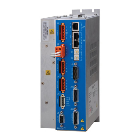
- Page 87 Xenus Plus User Guide 16-01344 Rev 06 Connector Locations Connector locations for 1-axis models are shown below. Connector locations for 2-axis models, are shown below. Note: J12 is on the upper end-panel. XE2/800-1819 800-1818/800-1887 Copley Controls...
-
Page 88: Ac Mains (J1)
Protective ground Chassis safety ground AC power input (L3) AC Mains Fuse Recommendation (All Xenus Plus models) Recommended fuse type: Class CC, 600 Vac rated, Ferraz-Shawmut ATDR, Littelfuse CCMR, Bussman LP-CC, or equivalent. AC Mains Wiring Diagram (Single-Phase) XEL/XPL/XML Copley Controls... - Page 89 The AC mains supplying the drive must be limited to over-voltages of Category II. The WARNING relevant standards assume AC mains with over-voltages per OVC III. An SPD or an isolation transformer is required to limit over-voltages to OVC II levels. Copley Controls...
- Page 90 Dual Axis models can exceed the overvoltage shutdown level (400V). In the event that commutation notches result in DC bus voltages above the overvoltage shutdown threshold in the end use system, measures to reduce commutation notch disturbances may be required. Copley Controls...
-
Page 91: Motor(S)
Motor frame ground and cable shield Phase W output of drive Phase V output of drive (use for DC motor connection) Phase U output of drive (use for DC motor connection) Brushless Motor Wiring Diagram Brush Motor Wiring Diagram Copley Controls... - Page 92 Motor frame ground and cable shield Phase W output of drive Phase V output of drive (use for DC motor connection) Phase U output of drive (use for DC motor connection) Brushless Motor Wiring Diagram Brush Motor Wiring Diagram Copley Controls...
-
Page 93: Regen Resistor (Optional)
Regen Resistor Fusing Recommended Fuses: Regen Resistor Fuse type XTL-RA-03 Cooper Bussman KLM-8, Littelfuse KLKD008, Ferraz Shawmut ATM-10 or equivalent. XTL-RA-04 Cooper Bussman KLM-12, Littelfuse KLKD012, Ferraz Shawmut ATM-15 or equivalent. User Supplied Regen Resistor Sizing and Configuration (p. 134). Copley Controls... - Page 94 A mating connector must be installed at location J2 whenever AC mains power is applied and within the capacitor discharge time. Otherwise the terminals of J2 are exposed and present a shock hazard under these conditions. Wiring Diagram – Integrated Regen Resistor Copley Controls...
- Page 95 Regen Resistor Fusing – External Regen Resistor Recommended Fuses: Regen Resistor Fuse type XTL-RA-03 Cooper Bussman KLM-8, Littelfuse KLKD008, Ferraz Shawmut ATM-10 or equivalent. XTL-RA-04 Cooper Bussman KLM-12, Littelfuse KLKD012, Ferraz Shawmut ATM-15 or equivalent. User Supplied Regen Resistor Sizing and Configuration (p. 134). Copley Controls...
-
Page 96: Logic Supply / Brake
Brake Return or low side of motor brake +24 Vdc +24 Vdc Logic power supply Logic Supply / Brake Wiring Diagram Drive Isolated Logic Power Supply Brake +24 V J4-3 +24 Vdc Brake Power J4-2 Supply J4-1 (Required) Copley Controls... - Page 97 J5-1 Isolated Logic Pow er Supply for Brake B Note that the +24Vdc supply must be a SELV or PELV type in applications using the XE2/XP2/XM2 STO feature. See the Xenus Plus Dual-Axis STO Manual for further details. Copley Controls...
-
Page 98: Ferrules - Xe2/Xp2/Xm2/800-1818/800-1819/800-1887
Gray 966144-2 15.0 (.59) 8.0 (.31) 1.70 (.07) 2.8 (.11) 5.0 (.20) 10 (.39) 2 x 22 2 x 0.50 White 966144-1 15.0 (.59) 8.0 (.31) 1.40 (.06) 2.5 (.10) 4.7 (.19) 10 (.39) SINGLE WIRE DOUBLE WIRE Copley Controls... -
Page 99: Motor Torque Off
2 inputs. When this is done the MTO feature is disabled and control of the output PWM stage is enabled, producing torque in the motor. If not using the MTO feature, these connections must be made for the Xenus Plus to be enabled. Copley Controls... - Page 100 Electrical connections to the MTO inputs should follow the requirements for fault exclusions for short circuits between conductors and short circuits between conductors and other conductive parts or earth or the protective bonding conductor. These requirements are given in ISO 13849-2 and IEC 61800-5-2:2016 for reference only. Copley Controls...
- Page 101 After the programmed delay time, contacts K3 and K4 open and de-energize the MTO inputs to the drive. The drive MTO function responds accordingly and the torque-off state is entered within the specified drive MTO response time. Copley Controls...
- Page 102 When the E-Stop button is pressed in, this is the time delay to the K3~K4 contact opening which will activate the MTO (3). MTO response time. This is the time between the de-energizing of the drive MTO inputs (K3~K4 contacts open) and the entry into the torque-off state. Copley Controls...
- Page 103 Contacts: AMP Tyco PN 66506-9, stamped, male, 10 micron gold, AWG 20-24 Backshell: Norcomp PN 970-009-020R121, metalized plastic with thumbscrews Other types may be suitable if they have crimp and poke contacts with gold flash or plating, and jack-screws for retention. MTO Receptacle J5 MTO Cable Connector Copley Controls...
-
Page 104: Safe Torque Off (Sto)
The information provided in the Xenus Plus Dual-Axis STO User Manual (document no. 16-01343) must be considered for any application using the XE2/XP2/XM2 drive STO feature. DANGER Failure to heed this warning can cause equipment damage, injury, or death. Copley Controls... - Page 105 It is important to note that the XE2/XP2/XM2/800-1818/800-1819/800-1887 and XEL/XPL/XML STO bypass connections are different. The diode shown in the muting/bypass plug should be used if XE2/XP2/XM2/800-1818/800-1819/800-1887 and XEL/XPL/XML drives are used on the same equipment. Otherwise, the diode may be replaced by a jumper. Copley Controls...
-
Page 106: Rs-232 Serial Communications
16-01344 Rev 06 4.9: RS-232 Serial Communications Mating Connector 6-position, modular connector (RJ-11 style). Copley Controls provides a prefabricated cable and modular-to-9-pin sub-D adapter in RS-232 Serial Cable Kit, PN SER-CK. A diagram of the female connector is shown below. Pin Description... -
Page 107: Network Ports
The XEL drive uses connector J7. The XE2/800-1818/800-1819/800-1887 drives use connector Drive TX + Jx-1 EtherCAT Network ("In") Jx-2 RX + Jx-3 Jx-4 Jx-5 RX - Jx-6 Jx-7 Jx-8 Opto-isolation TX + Jx-1 EtherCAT Network ("Out") Jx-2 RX + Jx-3 Jx-4 Jx-5 RX - Jx-6 Jx-7 Jx-8 Opto-isolation Copley Controls... - Page 108 Xenus Plus User Guide 16-01344 Rev 06 4.10.2: CAN Bus (XPL (J7), XP2 (J8)) Mating Connector 8-position, modular connector (RJ-45 style). Copley Controls provides the following assemblies: • Prefabricated 10 ft cable, PN XPL-NC-10 • Prefabricated 1 ft cable, PN XPL-NC-01 •...
- Page 109 The IN port connects to a master or to the OUT port of a device that is “upstream,” between the XML/XM2 and the master. The OUT port connects to “downstream” nodes. If XML/XM2 is the last node on a network, only the IN port is used. No terminator is required on the OUT port. Copley Controls...
-
Page 110: Control I/O
Multi-mode port /S2 Mode-dependent. See Mode-Dependent Dedicated Inputs (p. 111). Multi-mode port S2 Signal Ground Signal ground reference for inputs and outputs. OUT1 OUT2 Programmable outputs. OUT3 (HS) Signal Ground Signal ground for +5Vdc, inputs and outputs. Continued… Copley Controls... - Page 111 Up/Down IN 6 IN5(+) & IN6(-) B & /B Count Down IN 5 IN3(+) & IN4(-) A & /A Channel A Position Quadrature IN 6 IN5(+) & IN6(-) B & /B Channel B Digital Inputs (IN1~IN6) Wiring Diagram Copley Controls...
- Page 112 Drive + 5 Vdc 1.5 K MAX 3362 Motion J8-13 Controller J8-14 Position J8-21 1.5 K Encoder J8-22 J8-23 Typical Circuit J8-24 MAX 3097 J8-25 121 J8-26 Signal J8-15 Ground MAX 3032 Frame Gnd J8-1 Copley Controls...
- Page 113 Xenus Plus User Guide 16-01344 Rev 06 Analog Input Wiring Diagram Analog Output Wiring Diagram Drive 40.2 K 6.5V Measurement 100 A Out J8-9 -6.5V Sgnd J8-15 J8-1 Sgnd Frame gnd Copley Controls...
- Page 114 Optically isolated programmable input. IN13 GPI IN14 GPI OUT5+ GPI Optically isolated programmable output positive signal. OUT5- GPI Optically isolated programmable output negative signal. OUT4+ GPI Optically isolated programmable output positive signal. OUT4- GPI Optically isolated programmable output negative signal. Copley Controls...
- Page 115 4.7 K 4.99 K [IN10] J9-6 5.1V Opto-isolators [COMM_B] J9-7 4.7 K 4.99 K [IN11] J9-8 5.1V 4.7 K 4.99 K [IN12] J9-9 5.1V 4.7 K 4.99 K [IN13] J9-10 5.1V 4.7 K 4.99 K [IN14] J9-11 5.1V Copley Controls...
- Page 116 Xenus Plus User Guide 16-01344 Rev 06 Optically Isolated Programmable Outputs Wiring Diagram Copley Controls...
- Page 117 IN5 Diff2(-) IN11 Enable IN12 Diff3(+) IN13 Diff3(-) Mode dependent dedicated input. IN14 Diff4(+) Signal ground Signal ground reference for inputs and outputs. A + 5Vdc Out3 A-MultiEnc /S Programmable differential input/output port.. A-MultiEnc /X Programmable differential input/output port.. Copley Controls...
- Page 118 A & /A Count Up Position Up/Down IN 5 IN4(+) & IN5(-) B & /B Count Down IN 4 IN2(+) & IN3(-) A & /A Channel A Position Quadrature IN 5 IN4(+) & IN5(-) B & /B Channel B Copley Controls...
- Page 119 IN 15 IN14(+) & IN15(-) B & /B Count Down IN 14 IN12(+) & IN13(-) A & /A Channel A Position Quadrature IN 15 IN14(+) & IN15(-) B & /B Channel B Digital Inputs (IN1~IN5, IN11~IN15) Wiring Diagram Copley Controls...
- Page 120 Xenus Plus User Guide 16-01344 Rev 06 Analog Input Wiring Diagram Multi-Mode Port Interface Diagram Copley Controls...
- Page 121 No connection. No connection. COM2 Common signal for first group of optically isolated programmable inputs (IN16-IN19) IN19 GPI Optically isolated programmable input. OUT1+ GPI Optically isolated programmable output positive signal. OUT2+ GPI Optically isolated programmable output positive signal. Copley Controls...
- Page 122 IN19 GPI Optically isolated programmable input. OUT1+ GPI OUT2+ GPI Optically isolated programmable output positive signal. OUT3+ GPI S1_RTN S2_RTN S1_RTN~S4_RTN connect to the input diode cathodes of the optical limit switches on the motor. S3_RTN S4_RTN No connection. Copley Controls...
- Page 123 4.7 K 4.99 K [IN9] J9-5 5.1V Opto-isolators [COM2] J9-17 4.7 K 4.99 K [IN16] J9-7 5.1V 4.7 K 4.99 K [IN17] J9-8 5.1V 4.7 K 4.99 K [IN18] J9-9 5.1V 4.7 K 4.99 K [IN19] J9-18 5.1V Copley Controls...
- Page 124 Xenus Plus User Guide 16-01344 Rev 06 Optically Isolated Programmable Inputs Wiring Diagram, 800-1819/800-1887 Note: Wiring diagram for IN6 – IN9 on the 800-1819 and 800-1887 is the same as for the XE2/XP2/XM2/800-1818. Copley Controls...
- Page 125 Xenus Plus User Guide 16-01344 Rev 06 Optically Isolated Programmable Outputs Wiring Diagram, XE2/XP2/XM2/800-1818/800-1819/800-1887 J9 Wiring Signal Pins Signal Pins [OUT1+] [OUT1-] [OUT2+] [OUT2-] [OUT3+] [OUT3-] [OUT4+] [OUT4-] [OUT5+] [OUT5-] Note: Model 800-1819/800-1887 does not have OUT4 and OUT5. Copley Controls...
-
Page 126: Motor Feedback
Norcomp: 180-026-103L001 24 - 30 AWG Style Connector Back shell Norcomp: 979-015-020R121 Solder style connector included in Connector Kits XEL-CK, XE2-CK, XPL-CK, XP2-CK, XML-CK, and XM2-CK. Pin connections for the bulkhead connector on the drive are shown here: Copley Controls... - Page 127 Sin1(+) Cos1(-) Analog Sin/Cos/Index encoder signals. Cos1(+) Index1(-) Index1(+) IN15 (XEL/XPL/XML) General purpose input IN21/IN22 (XE2/XP2) (IN21 is on J10, IN22 is on J11) Signal Ground Signal and +5 Vdc ground. Signal Ground Signal and +5 Vdc ground. Copley Controls...
- Page 128 Resolver Abs A Resolver Abs B Type 2 motor only Resolver Abs C No connection Signal Ground Signal and +5 Vdc ground. +5 Vdc Encoder +5 Vdc power supply output. Resolver Inc A Type 2 & Type 1 motors Copley Controls...
- Page 129 Signal and +5 Vdc ground. Quad A/B Incremental Encoder Wiring Diagram In XEL/XPL/XML there are two encoder +5V outputs at 400 mA each, and in the XE2/XP2/XM2/800-1818/800- 1819/800-1887 there are 4 encoder +5V outputs at 500 mA each. Copley Controls...
- Page 130 Halls J10-6 @ 400 mA Power J10-5 Frame Gnd J10-1 Case Ground In XEL/XPL/XML there are two encoder +5V outputs at 400 mA each, and in the XE2/XP2/XM2/800-1818 there are 4 encoder +5V outputs at 500 mA each. Copley Controls...
- Page 131 + 5 VDC J10-17 @ 400 mA Power J10-5 Case Frame Gnd J10-1 Ground In XEL/XPL/XML there are two encoder +5V outputs at 400 mA each, and in the XE2/XP2/XM2/800-1818 there are 4 encoder +5V outputs at 500 mA each. Copley Controls...
- Page 132 Xenus Plus User Guide 16-01344 Rev 06 Resolver Wiring Diagram Drive REF(+) J10-23 REF(-) J10-22 Resolver SIN (+) J10-19 SIN (-) J10-18 COS (+) J10-21 COS (-) J10-20 Frame Gnd J10-1 Case Ground Resolver Wiring Diagram, 800-1819/800-1887 Copley Controls...
- Page 133 J10 -7 Thermistor, Posistor , or Switch J10 -5 Motor Over Temperature Wiring Diagram: XE2/XP2/XM2/800-1818/800-1819/800-1887 Drive J10, J11 +5 V Thermistor, 5k Posistor or Switch 10k J10,J11-7 33 nƒ J10,J11-5 General Purpose Input Wiring Diagram: XE2/XP2/XM2/800-1818/800-1819/800-1887 Copley Controls...
-
Page 134: A: Regen Resistor Sizing And Configuration
To configure a custom regen resistor, see the CME User Guide. Additional information about regeneration can be found in this document on the web-site: http://www.copleycontrols.com/Motion/pdf/Xenus_regen_guide-03-04.pdf The contents of this chapter include: A.1: Sizing a Regen Resistor ................................. 135 Copley Controls... -
Page 135: A.1: Sizing A Regen Resistor
A.1.2: Observe the Properties of Each Deceleration During a Complete Cycle of Operation For each deceleration during the motion cycle, determine: Speed at the start of the deceleration Speed at the end of the deceleration Time over which the deceleration takes place. Copley Controls... - Page 136 Calculate the amount of energy that will be returned to the drive for each deceleration using the following formula. returned motor Where: = Energy returned to the drive, in Joules returned = Energy returned by the deceleration, in Joules = Energy dissipated by the motor, in Joules motor Copley Controls...
- Page 137 = The voltage at which the regen circuit turns on. regen Choose a standard value of resistance less than the calculated value. This value must be greater than the minimum regen resistor value specified in Regen Circuit Output (p. 67). Copley Controls...
- Page 138 Where: = The minimum continuous current rating the fuse requires in Amps. cont = The continuous power calculated in the previous step, in Watts. cont = The voltage at which the regen circuit turns on. regen Copley Controls...
-
Page 139: B: I 2 T Time Limit Algorithm
T limit specifies the maximum amount of time that the peak current can be applied to the motor before it must be reduced to the continuous limit or generate a fault. This chapter describes the algorithm used to implement the I T limit. Contents Include: B.1: I T Algorithm ................................... 140 Copley Controls... -
Page 140: B.1: I 2 T Algorithm
Continuous Current Limit if the commanded current is greater than the Continuous Current Limit. If instead the commanded current is less than or equal to the Continuous Current Limit, the output current will be equal to the commanded current. Copley Controls... - Page 141 6 A up to 12 A over the course of 1.2 seconds. During this same period, the T Accumulator Variable increases in a non-linear fashion because of its dependence on the square of the current. Copley Controls...
- Page 142 T Accumulator Variable value continues to fall until at approximately 5.0 seconds when the commanded current goes above the continuous current limit again. The actual output current follows the current command until the I T Accumulator Variable value reaches the I T setpoint and current limiting is invoked. Copley Controls...
-
Page 143: C: Thermal Considerations
Xenus Plus User Guide 16-01344 Rev 06 APPENDIX C: T HERMAL ONSIDERATIONS This chapter describes operating temperature characteristics, heatsink options, and heatsink mounting instructions. Contents include: C.1: Operating Temperature and Cooling Configurations ......................144 C.2: Heatsink Mounting Instructions (XEL/XPL/XML) ........................148 Copley Controls... -
Page 144: C.1: Operating Temperature And Cooling Configurations
Low Profile Low Profile Heatsink w/fan Heatsink w/fan Low Profile Heatsink Low Profile Heatsink or no Heatsink w/fan or no Heatsink w/fan Standard Standard Heatsink Heatsink No Heatsink No Heatsink Continuous Output Current (Adc) Continuous Output Current (Adc) Copley Controls... - Page 145 Care must be taken in mounting the drives to ensure that airflow is not impeded. The heatsink/fan surface of the drive should be at least 1.5 in (38.1mm) from any other surface, including other drives, for adequate cooling. Copley Controls...
- Page 146 The following chart shows the maximum allowable ambient temperature as a function of output current for the model 800-1818 drive. Data is given for two different mounting configurations with the drive operating from maximum rated mains input voltage. Copley Controls...
- Page 147 120 VAC MAINS Top view Vertical mounting No heatsink No fan Top view Vertical mounting No Heatsink With fan 240 VAC MAINS Top view Vertical mounting Heatsink No fan Top view Vertical mounting Heatsink With fan Copley Controls...
-
Page 148: C.2: Heatsink Mounting Instructions (Xel/Xpl/Xml)
Torque the #8-32 mounting screws to 16~20 lb-in (1.8~2.3 Nm). NOTE: The drawing shows the standard heatsink kit but the mounting instructions given are valid for the low profile heatsink kit as well. Copley Controls... -
Page 149: C.3: Heatsink Mounting Instructions (Xe2/Xp2/Xm2, "-N" And 800-1887 Models)
5) Install the four mounting screws with XE2 grounding flat washers and tighten evenly. lug hole. Torque to 17.8 lb-in (2.0 Nm) Thermal material maximum. Thermal material placement area Copley Controls... -
Page 150: D: Xenus Plus Filter
Xenus Plus User Guide 16-01344 Rev 06 APPENDIX D: X ENUS ILTER This chapter provides an overview of the Model XTL-FA-01 edge filter. Contents include: D.1: Overview ....................................151 D.2: XTL-FA-01 Edge Filter Wiring ..............................154 Copley Controls... -
Page 151: D.1: Overview
The differential filter increases the rise time by at least a factor of 3, substantially reducing noise in the system. Copley Controls drives typically have a 150 ns rise-time (high frequency component in the MHz range). Thus, the edge filter can increase rise time to 500 ns, reducing the high frequency noise emissions by the square law. - Page 152 Mount the filter on edge and mount the fan below it so that it blows up through the cover slots. There is no heatsink option for the XTL-FA-01 edge filter. Copley Controls...
- Page 153 Xenus Plus User Guide 16-01344 Rev 06 D.1.5: XTL-FA-01 Edge Filter Dimensions The following diagram shows the mounting dimensions of the XTL-FA-01 Edge Filter. Copley Controls...
-
Page 154: D.2: Xtl-Fa-01 Edge Filter Wiring
J2, all of the other circuits on these connectors are mains-connected and must never be grounded. WARNING Failure to heed this warning can cause equipment damage. D.2.2: Connector Locations Edge Filter J1 connects to Xenus Plus J2 (J3 or J4 for XE2/XP2/XM2/800-1818/800-1819). Edge Filter J2 connects to the motor. Copley Controls... - Page 155 Function Ground Chassis ground and cable shield Phase W Phase W output to motor Phase V Phase V output to motor (use for DC motor connection) Phase U Phase U output to motor (use for DC motor connection) Copley Controls...
- Page 156 Filter Model Description XTL-FA-01 Xenus Plus Edge Filter Connector Kit Model Description Mfr. Model No. Plug, 5 position, 5.0 mm, female Wago: 721-105/026-047 XTL-FK Plug, 4 position, 5.0 mm, female Wago: 721-104/026-047 Insertion / Extraction Tool Wago: 231-131 Copley Controls...
-
Page 157: E: Connecting Xpl/Xp2 For Serial Control
16-01344 Rev 06 APPENDIX E: C XPL/XP2 ONNECTING ERIAL ONTROL This chapter describes how to connect one or more XPL/XP2 drives for control via the RS-232 bus on one of the drives. Contents Include: E.1: Single-Axis and Multi-Drop ..............................158 Copley Controls... -
Page 158: E.1: Single-Axis And Multi-Drop
For experimentation and simple setup and control, a telnet device such as the standard Microsoft Windows HyperTerminal can also be used to send commands in ASCII format. For more information, see Copley Controls ASCII RS-232 User Guide. The serially connected drive can also be used as a multi-drop gateway for access to other drives linked in a series of CAN bus connections. -
Page 159: F: Ordering Guide And Accessories
F.1: Drive Model Numbers ................................160 F.2: Accessory Model Numbers ..............................163 F.3: Heatsink Kits ................................... 164 F.4: Regen Resistor Assemblies ..............................165 F.5: Edge Filter ....................................165 F.6: Order Example ..................................165 F.7: Copley Standard Regen Resistor Specifications ........................166 Copley Controls... -
Page 160: F.1: Drive Model Numbers
Xenus Plus 2-Axis EtherCAT Servo drive 4.5/9 A, encoder feedback 800-1819 Custom Xenus Plus 2-Axis EtherCAT Servo drive 10/20 A, resolver feedback Custom Xenus Plus 2-Axis EtherCAT Servo drive 10/20 A, res fdbk, no heatsink, fan or internal 800-1887 regen resistor Copley Controls... - Page 161 Xenus Plus 2-Axis CANopen Servo drive 10/20 A, resolver feedback Xenus Plus 2-Axis CANopen Servo drive 10/20 A, enc fdbk, no heatsink, fan or internal regen XP2-230-20-N Xenus Plus 2-Axis CANopen Servo drive 10/20 A, res fdbk, no heatsink, fan or internal regen XP2-230-20-R-N Copley Controls...
- Page 162 Xenus Plus 2-Axis MACRO Servo drive 10/20 A, resolver feedback XM2-230-20-N Xenus Plus 2-Axis MACRO Servo drive 10/20 A, enc fdbk, no heatsink, fan or internal regen res XM2-230-20-R-N Xenus Plus 2-Axis MACRO Servo drive 10/20 A, res fdbk, no heatsink, fan or internal regen res Copley Controls...
-
Page 163: F.2: Accessory Model Numbers
SER-CK RS-232 Serial Cable Kit ® XE2-NC-10 EtherCAT network cable, 10 ft (3 m) Network ® XE2-NC-01 EtherCAT network cable, 1 ft (0.3 m) Note 1: Insertion/extraction tool for J6 contacts is AMP/Tyco 91067-2 (not included in XP2-CK) Copley Controls... -
Page 164: F.3: Heatsink Kits
Heatsink thermal material XML-HS Heatsink hardware mounting kit XE2/XP2/XM2, “-N” and 800-1887 Models Model Description Heatsink, standard XE2-HS XP2-HS Heatsink thermal material XM2-HS Heatsink hardware mounting kit These kits contain the parts needed for field installation of a heatsink. Copley Controls... -
Page 165: F.4: External Regen Resistor Assemblies
Order 1 XEL-230-18 drive with standard heatsink fitted at the factory, Connector Kit, and serial cable Item Description kit: XEL-230-18-HS Xenus Plus EtherCAT Servo drive with standard heatsink installed XEL-CK Connector Kit with solder cup connectors SER-CK Serial Cable Kit for connecting the PC to the drive Copley Controls... -
Page 166: F.7: Copley Standard Regen Resistor Specifications
Setting Default Continuous Power for a standard Copley regen resistor to a value greater than the default of 65 W may cause the resistor casing to heat to temperatures that could cause injury. If higher settings are required, contact Copley Controls customer support. WARNING Failure to heed this warning can cause equipment damage or injury. - Page 167 Xenus Plus User Guide 16-01344 Revision 06 August 30, 2019 © 2019 Copley Controls Analogic Motion Controls 20 Dan Road Canton, MA 02021 USA All rights reserved...
Need help?
Do you have a question about the Xenus Plus Series and is the answer not in the manual?
Questions and answers