Table of Contents
Advertisement
Quick Links
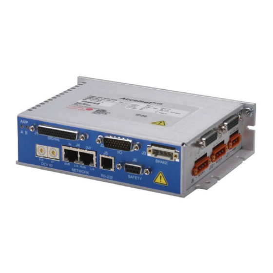
Accelnet
dIgItal serVo drIVe for brush & brushless Motors
ConTRol MoDES
• Cyclic Synchronous Position-Velocity-Torque (CSP, CSV, CST)
• Profile Position-Velocity-Torque, Interpolated Position, Homing
• Camming, Gearing
• Indexer
Command InTerfaCe
• Canopen application protocol over etherCaT (Coe)
• aSCII and discrete I/o
• Stepper commands
• ±10V position/velocity/torque
• PWm velocity/torque command
• master encoder (Gearing/Camming)
CommunICaTIonS
• etherCaT
• rS-232
FEEDBACk
Incremental Encoders
• digital quad a/B
analog Sin/Cos
Panasonic Incremental a format
• aux. quad a/B encoder / encoder out
Absolute Encoders
• SSI, endat, absolute a,
Tamagawa & Panasonic Absolute A
Sanyo denki absolute a, BiSS (B & C)
Other
• digital Halls
I/o dIGITal
• 8 High-speed inputs
• 2 motor over-temp inputs
• 8 opto-Isolated inputs
• 5 opto-Isolated outputs
• 2 opto-Isolated brake outputs
analoG
• 2 reference Inputs, 12-bit
Safe Torque off (STo)
• SIl 3, Category 3, Pl d
dImenSIonS: In [mm]
• 6.78 x 4.70 x 1.74 [172.1 x 119.3 x 44.1] no heatsink
• 6.78 x 4.70 x 3.14 [172.1 x 119.3 x 79.8] with heatsink
deSCrIPTIon
The BEl models are high-performance, DC powered drives for
position, velocity, and torque control of brushless and brush motors
via etherCaT, an ethernet-based fieldbus. These drives operate
as EtherCAT slaves using the CAnopen application protocol over
etherCaT (Coe) protocol of dSP-402 for motion control devices.
Supported modes include: Cyclic Synchronous Position-Velocity-
Torque, Profile Position-Velocity-Torque, Interpolated Position mode
(PVT), and Homing.
Feedback from both incremental and absolute encoders is
supported. A multi-mode encoder port functions as an input or
output depending on the drive's basic setup.
Copley Controls, 20 Dan Road, Canton, MA 02021, USA
Web: www.copleycontrols.com
Plus
2-Axis Panel EtherCAT
There are ten non-isolated inputs and eight isolated inputs.
All inputs have programmable active levels. Five opto-isolated
outputs [ouT1~5] have individual +/- connections. Two isolated
moSfeT brake outputs [ouT6~7] are programmable for other
functions and have flyback diodes to the Brake 24V input for driving
inductive loads.
Drive power is transformer-isolated DC from regulated or
unregulated power supplies. an auxHV input is provided for
"keep-alive" operation permitting the drive power stage to be
completely powered down without losing position information, or
communications with the control system.
Model
Ip
BE2-090-06
6
BE2-090-14
14
BE2-090-20
20
Current ratings are for each axis
Add -R for resolver feedback option
Tel: 781-828-8090
BE2
RoHS
Ic
Vdc
3
90
7
90
10
90
Fax: 781-828-6547
Page 1 of 33
Advertisement
Table of Contents

Related Manuals for Copley Controls Accelnet Plus Dual-Axis Panel EtherCAT


Summary of Contents for Copley Controls Accelnet Plus Dual-Axis Panel EtherCAT
- Page 1 A multi-mode encoder port functions as an input or completely powered down without losing position information, or output depending on the drive’s basic setup. communications with the control system. Copley Controls, 20 Dan Road, Canton, MA 02021, USA Tel: 781-828-8090 Fax: 781-828-6547 Web: www.copleycontrols.com...
-
Page 2: General Specifications
Full-duplex, DTE serial communication port for drive setup and control, 9,600 to 115,200 Baud Protocol Binary and aSCII formats eTHerCaT PorTS format dual rJ-45 receptacles, 100BaSe-Tx Protocol EtherCAT, CAnopen application protocol over etherCaT (Coe), Cia-402 for motion control devices noTES: 1) Heatsink or forced-air required for continuous current rating Copley Controls, 20 Dan Road, Canton, MA 02021, USA Tel: 781-828-8090 Fax: 781-828-6547 Web: www.copleycontrols.com Page 2 of 33... - Page 3 Cooling Heat sink and/or forced air cooling required for continuous power output aGenCy STandardS ConformanCe (PendInG) Approvals ul and cul recognized component to ul 61800-5-1 (file no. e168959) TÜV SÜd functional Safety to IeC 61508 and ISo 13849 <pending> Functional Safety IeC 61508-1, IeC 61508-2, en (ISo ) 13849-1, en (ISo) 13849-2, IeC 61800-5-2 (see The Accelnet & Stepnet Plus Panels STO Manual for further detail) Electrical Safety directive 2006/95/eC – low Voltage: IeC 61800-5-1:2007 Ul 61800-5-1-2012 directive 2004/108/eC – emC: RoHS IeC 61800-3:2004+a1:2011 Hazardous Substances directive 2011/65/eu (roHS directive) Copley Controls, 20 Dan Road, Canton, MA 02021, USA Tel: 781-828-8090 Fax: 781-828-6547 Web: www.copleycontrols.com Page 3 of 33...
- Page 4 Brushless, single-speed, 1:1 to 2:1 programmable transformation ratio resolution 14 bits (equivalent to a 4096 line quadrature encoder) reference frequency 8.0 kHz reference voltage 2.8 Vrms max, auto-adjustable by the drive to adjust sin/cos signals to 2.0 Vrms Reference maximum current 100 mA Maximum RPM 10,000 typical Sin/Cos inputs differential, 54kW ±1% differential impedance, 2.0 Vrms, BW ≥ 300 kHz Copley Controls, 20 Dan Road, Canton, MA 02021, USA Tel: 781-828-8090 Fax: 781-828-6547 Web: www.copleycontrols.com Page 4 of 33...
-
Page 5: Ethercat Communications
• Short circuit (Internal or external) • over-voltage • drive over-temperature • under-voltage • motor over-temperature • motor Phasing error • feedback error • Command Input fault • following error DEV ID NETWOR Copley Controls, 20 Dan Road, Canton, MA 02021, USA Tel: 781-828-8090 Fax: 781-828-6547 Web: www.copleycontrols.com Page 5 of 33... - Page 6 After power-on, reset, or transmission of a Break character, the Baud rate will be 9,600. once communication has been established at this speed, the Baud rate can be changed to a higher rate (19,200, 57,600, 115,200). aSCII parameter 0x90 holds the Baud rate data. To set the rate to 115,200 enter this line from a terminal: s r0x90 115200 <enter> Then, change the Baud rate in the computer/controller to the new number and communicate at that rate. additional information can be found in the aSCII Programmers Guide on the Copley website: http://www.copleycontrols.com/motion/pdf/aSCII_ProgrammersGuide.pdf Copley Controls, 20 Dan Road, Canton, MA 02021, USA Tel: 781-828-8090 Fax: 781-828-6547 Web: www.copleycontrols.com Page 6 of 33...
-
Page 7: Installation
7 and 9. STO-Bypass (6.5 mA) STO-Gnd (Sgnd) Frame Ground ConneCTIonS SafeTy ConneCTor J6 SIGnal SIGnal frame Gnd STo-In1+ STo-In1+ STo-In1- STo-In1- STo-Bypass STo-In2+ STo-Gnd STo-In2- Copley Controls, 20 Dan Road, Canton, MA 02021, USA Tel: 781-828-8090 Fax: 781-828-6547 Web: www.copleycontrols.com Page 7 of 33... - Page 8 [IN3(12)] [enc B] Pol-dir J1-35 J1-41 Curr-Vel± [enc /B] /Pol-dir J1-20 J1-26 [IN4(13)] <no connection> <not used> J1-6,16,22,31, <no connection> Signal Ground 37,44 Multi-port J1-1 frame Ground Copley Controls, 20 Dan Road, Canton, MA 02021, USA Tel: 781-828-8090 Fax: 781-828-6547 Web: www.copleycontrols.com Page 8 of 33...
- Page 9 +5V output @ 500 mA Input Signal Ground Select Input/Output Select 4-Wire digital absolute 2-Wire digital absolute encoder signals Output encoder signals Select MAX3362 MAX3362 Copley Controls, 20 Dan Road, Canton, MA 02021, USA Tel: 781-828-8090 Fax: 781-828-6547 Web: www.copleycontrols.com Page 9 of 33...
-
Page 10: Output Types
Buffered A/B/X signals Select from primary encoder MAX3362 MAX3032 Emulated Quad A/B Quad A/B/X primary signals from encoder analog Sin/Cos encoder Copley Controls, 20 Dan Road, Canton, MA 02021, USA Tel: 781-828-8090 Fax: 781-828-6547 Web: www.copleycontrols.com Page 10 of 33... - Page 11 Vloop: output filter 3 Disabled Motor Wiring Iloop: Input filter 1 Disabled Disconnected Iloop: Input filter 2 Disabled STo Active Input Shaping Disabled oPTIonal faulTS over Current (latched) Axes A, B notes Method Set Current Position as Home Copley Controls, 20 Dan Road, Canton, MA 02021, USA Tel: 781-828-8090 Fax: 781-828-6547 Web: www.copleycontrols.com Page 11 of 33...
-
Page 12: Specifications
In12 In12+ J1-14 3) Vdiff = aInn(+) - aInn(-) n = 1 for Axis A, 2 for Axis B In13 In12- J1-15 [IN4,13] Sgnd J1-6, 16, 22, 31, 37 , 44 Copley Controls, 20 Dan Road, Canton, MA 02021, USA Tel: 781-828-8090 Fax: 781-828-6547 Web: www.copleycontrols.com Page 12 of 33... - Page 13 Pins J2-2 In14 J2-7 4.7k [IN8(17)] J2-3 In15 J2-8 4.99k 5.1V J2-4 In16 J2-9 J2-5 In17 J2-18 ICom1 J2-6 ICom2 J2-17 Copley Controls, 20 Dan Road, Canton, MA 02021, USA Tel: 781-828-8090 Fax: 781-828-6547 Web: www.copleycontrols.com Page 13 of 33...
- Page 14 Condition output SSr is on, current flows ouT1~5 ConneCTIonS output SSr is off, no current flows Signal oUT1 J2-19 J2-10 oUT2 J2-20 J2-11 oUT3 J2-21 J2-12 oUT4 J2-22 J2-13 oUT5 J2-23 J2-14 Copley Controls, 20 Dan Road, Canton, MA 02021, USA Tel: 781-828-8090 Fax: 781-828-6547 Web: www.copleycontrols.com Page 14 of 33...
- Page 15 Heatplate/chassis Earth Ground Earthing connections for power supplies should be as close as possible to elimimate potential differences between power supply 0V terminals. Copley Controls, 20 Dan Road, Canton, MA 02021, USA Tel: 781-828-8090 Fax: 781-828-6547 Web: www.copleycontrols.com Page 15 of 33...
-
Page 16: Feedback Connections
6, 17 Sgnd = Signal Ground +5V Out @ 500 mA f.G. = frame Gnd Sgnd 5, 16, 25, 26 Signal Ground Signal Ground f.G. Sgnd = Signal Ground f.G. = frame Gnd Copley Controls, 20 Dan Road, Canton, MA 02021, USA Tel: 781-828-8090 Fax: 781-828-6547 Web: www.copleycontrols.com Page 16 of 33... -
Page 17: Ssi Absolute Encoder
/data f.G. 6, 17 Sgnd = Signal Ground f.G. = frame Gnd +5V Out @ 500 mA Sgnd 5, 16, 25, 26 f.G. Signal Ground Sgnd = Signal Ground f.G. = frame Gnd Copley Controls, 20 Dan Road, Canton, MA 02021, USA Tel: 781-828-8090 Fax: 781-828-6547 Web: www.copleycontrols.com Page 17 of 33... -
Page 18: Motor Connections
J7-7 Resistance in the temperature range 60~750 20°C to +70°C Motemp B J8-7 resistance at 85°C ≤1650 J7,J8 5,10 Signal Ground resistance at 95°C ≥3990 frame Gnd resistance at 105°C ≥12000 Copley Controls, 20 Dan Road, Canton, MA 02021, USA Tel: 781-828-8090 Fax: 781-828-6547 Web: www.copleycontrols.com Page 18 of 33... - Page 19 1) The +5Vout1 on J1-17,32 and J7-6, 17 is rated for 500 ma The +5Vout2 on J1-23,38 and J8-6, 17 is rated for 500 ma These are two independent power supplies, each with a 500 mA max output from all pins Ce symbols indicate connections required for Ce compliance. Copley Controls, 20 Dan Road, Canton, MA 02021, USA Tel: 781-828-8090 Fax: 781-828-6547 Web: www.copleycontrols.com Page 19 of 33...
- Page 20 1) The +5Vout1 on J1-17,32 and J7-6, 17 is rated for 500 ma The +5Vout2 on J1-23,38 and J8-6, 17 is rated for 500 ma These are two independent power supplies, each with a 500 mA max output from all pins Ce symbols indicate connections required for Ce compliance. Copley Controls, 20 Dan Road, Canton, MA 02021, USA Tel: 781-828-8090 Fax: 781-828-6547 Web: www.copleycontrols.com Page 20 of 33...
- Page 21 1) The +5Vout1 on J1-17,32 and J7-6, 17 is rated for 500 ma The +5Vout2 on J1-23,38 and J8-6, 17 is rated for 500 ma These are two independent power supplies, each with a 500 mA max output from all pins Ce symbols indicate connections required for Ce compliance. Copley Controls, 20 Dan Road, Canton, MA 02021, USA Tel: 781-828-8090 Fax: 781-828-6547 Web: www.copleycontrols.com Page 21 of 33...
- Page 22 J1 Control [IN5~8,14~17] [IN9,18] Sgnd Isolated [OUT1~5+] [AIN1~2+/-] Sgnd J2 I/O [OUT1~5-] Sgnd Sgnd DRIVE CIRCUITS HEATPLATE BE2 Heatplate Protective Earth ground Copley Controls, 20 Dan Road, Canton, MA 02021, USA Tel: 781-828-8090 Fax: 781-828-6547 Web: www.copleycontrols.com Page 22 of 33...
-
Page 23: Power & Grounding Connections
Mains Ground Green/Yellow Power Unregulated Connector P-Clip 1-Axis = J7 Power Supply 2-Axis = J10 Equipment Ground Frame Ground Earth Ground Copley Controls, 20 Dan Road, Canton, MA 02021, USA Tel: 781-828-8090 Fax: 781-828-6547 Web: www.copleycontrols.com Page 23 of 33... -
Page 24: Energy Absorption
When the load mechanical energy is greater than these values an external regenerative energy dissipater is required, or the dC power supply capacitance can be increased to absorb the regen energy. Copley Controls, 20 Dan Road, Canton, MA 02021, USA Tel: 781-828-8090 Fax: 781-828-6547 Web: www.copleycontrols.com Page 24 of 33... - Page 25 B-MultiEnc S [In4] diff1(-) B-multienc /x B-multienc x B-multienc /B B-MultiEnc B [In10] B-multienc /a B-MultiEnc A [In11] 30 44 [In12] diff2(+) Signal Gnd [In13] diff2(-) J1: Be2 ConneCTor High-density dsub dB-44f, female receptacle, 44 Position J2: CaBle ConneCTor High-density dsub dB-44m, male plug, 44 Position Copley Controls, 20 Dan Road, Canton, MA 02021, USA Tel: 781-828-8090 Fax: 781-828-6547 Web: www.copleycontrols.com Page 25 of 33...
- Page 26 Euro-style 5.08 mm male receptacle, 4-position J11: CaBle ConneCTor Wago: mCS-mIdI, 231-564/108-000 Wago mCS-mIdI, 231-303/107-000 J9, J10 CaBle ConneCTorS Wago mCS-mIdI Classic 231-304/107-000 WaGo ConneCTor Tool Contact opener: 231-131 operating tool WaGo ConneCTor Tool Contact opener: 231-131 operating tool Copley Controls, 20 Dan Road, Canton, MA 02021, USA Tel: 781-828-8090 Fax: 781-828-6547 Web: www.copleycontrols.com Page 26 of 33...
- Page 27 3.3 (.13) 8 (.31) White Wago 216-221 12.0 (.47) 6.0 (.24) 1.0 (.039) 2.6 (.10) 3.1 (.12) 7.5 (.30) noTES PnUM = Part number Sl = Stripping length dimensions: mm (in) Copley Controls, 20 Dan Road, Canton, MA 02021, USA Tel: 781-828-8090 Fax: 781-828-6547 Web: www.copleycontrols.com Page 27 of 33...
- Page 28 HSnf = Heat Sink no fan nHSnf = no Heat Sink no fan 19 W 8W 10W 12W 14W 16W 18W 20W 22W 24W 26W Internal power dissipation (Watts) Copley Controls, 20 Dan Road, Canton, MA 02021, USA Tel: 781-828-8090 Fax: 781-828-6547 Web: www.copleycontrols.com Page 28 of 33...
- Page 29 °C/W forCED-Air, 300 lfm 0.98 ConVeCTIon 2.32 heatsink, no fan °C/W heatsink + fan °C/W ConvECtion 1.28 forCED-Air, 300 lfm 0.61 Copley Controls, 20 Dan Road, Canton, MA 02021, USA Tel: 781-828-8090 Fax: 781-828-6547 Web: www.copleycontrols.com Page 29 of 33...
- Page 30 4) align the Be2 as shown and lower onto the heatsink. If needed to adjust the position, lift it away from the thermal material and lower onto the heatsink again. 5) Install the four mounting screws with flat washers and tighten evenly. Torque to 17.8 lb-in (2.0 nm) maximum. Mounting Screws (4) Drive Thermal material Heatsink Copley Controls, 20 Dan Road, Canton, MA 02021, USA Tel: 781-828-8090 Fax: 781-828-6547 Web: www.copleycontrols.com Page 30 of 33...
- Page 31 0.16 [4.1] 0.16 [4.1] 0.85 [21.5] 0.89 [22.6] Mounting screws: #6-32, or 3.5 mm 0.19 [4.8] 4.89 [124.3] 4.70 [119.3] 0.16 [4.1] 1.74 [44.1] Copley Controls, 20 Dan Road, Canton, MA 02021, USA Tel: 781-828-8090 Fax: 781-828-6547 Web: www.copleycontrols.com Page 31 of 33...
- Page 32 0.85 [21.5] 0.85 [21.5] 2.29 [58.1] 2.29 [58.1] Mounting screws: #6-32, or 3.5 mm 4.89 [124.3] 4.70 [119.3] 0.19 [4.8] 0.16 [4.1] 3.14 [79.98] Copley Controls, 20 Dan Road, Canton, MA 02021, USA Tel: 781-828-8090 Fax: 781-828-6547 Web: www.copleycontrols.com Page 32 of 33...
-
Page 33: Ordering Guide
BE2-nC-01 EtherCAT network cable, 1 ft (0.3 m) ® note 1: Insertion/extraction tool for J6 contacts is amP/Tyco 91067-2 (not included in Be2-CK) note 2: for roHS compliance, append “/rn01-0000” to the Wago part numbers listed above HeaTSInK KIT for fIeld InSTallaTIon (oPTIonal) Be2 Heatsink Be2-HK Heatsink Heatsink thermal material Heatsink hardware etherCaT is a registered trademark and patented technology, licensed by Beckhoff automation GmbH, Germany. Note: Specifications subject to change without notice Copley Controls, 20 Dan Road, Canton, MA 02021, USA Tel: 781-828-8090 Fax: 781-828-6547 Web: www.copleycontrols.com Page 33 of 33...
Need help?
Do you have a question about the Accelnet Plus Dual-Axis Panel EtherCAT and is the answer not in the manual?
Questions and answers