Abus SECVEST Installer Manual
Hide thumbs
Also See for SECVEST:
- Installation instructions and user manual (181 pages) ,
- User manual (82 pages) ,
- Installer manual (260 pages)

Related Manuals for Abus SECVEST


Summary of Contents for Abus SECVEST
- Page 1 ABUS | Security-Center abus.com SECVEST Installer manual V3.01.14...
-
Page 2: Limitation Of Liability
Everything possible has been done to ensure that the content of these instructions is correct. However, neither the author nor ABUS Security-Center GmbH & Co. KG can be held liable for loss or damage caused by incorrect or im- proper installation and operation or failure to observe the safety instructions and warnings. No liability can be accepted for resulting damage. -
Page 3: Declaration Of Conformity
Contents Declaration of conformity ABUS Security-Center hereby declares that the radio equipment type FUAA50xxx is in compliance with RED Directive 2014/53/EU. The full EU Declaration of Conformity text can be found at: www.abus.com Item search FUAA50xxxx/Downloads. The Declaration of Conformity can also be obtained from the following address: ABUS Security-Center GmbH &... -
Page 4: Table Of Contents
Contents .................................... 4 Quickstart guide ................................8 Target audience ................................8 Installing Secvest ................................8 Configuring Secvest ................................. 8 Secvest function test ................................ 8 Safety information ................................9 Explanation of symbols ..............................9 Intended use ..................................9 General ..................................10 Power supply ................................. - Page 5 Contents Main menu ..................................48 INFO ....................................50 Alarm panel ................................50 Communication ................................. 54 PSTN ..................................55 Ethernet................................. 56 Mobile..................................57 Hybrid module ................................59 Customisation ................................60 Status ..................................... 61 Components .................................. 62 Teach-in via web interface............................62 Detectors ..................................
- Page 6 Contents Report ..................................182 Communication ................................184 Network ................................... 184 Network setup ..............................185 IP Mobile Setup ..............................187 Email setup ................................. 192 VoIP dialler setup ..............................194 ARC reporting ................................. 196 ARC Reporting, Phone Book ..........................199 ARC Reporting, Account Numbers ........................201 ARC Reporting, Fast Fmt Channels (for "Fast Format"...
- Page 7 Contents ARC/ESCC reporting ..............................340 ARC/ESCC reporting protocol formats ........................340 CID/SIA Events ............................... 344 Email error messages ..............................355 TCP/IP error messages ............................... 356 Overview of the SSL-relevant messages ........................356 VoIP error messages ..............................358 GSM CME / CMS Error messages ..........................359 CME Error codes ..............................
-
Page 8: Quickstart Guide
Installing Secvest Provide the user with the user manual and the quick start guide and, where applicable, these in- The installation of the Secvest wireless alarm system is stallation instructions. described in chapter Mounting/Installation from page 37. Additional information can be found in the document sup- plied in the scope of delivery, "Quick Guide FUAA50000". -
Page 9: Safety Information
Further general information and infor- Note Indicates important information. mation on product support can be found at www.abus.com on the general page or for dealers and in- stallers, in the Partner portal. The EU Directive WEEE 2012/19/EU governs the proper... -
Page 10: General
Safety information General Before using this device for the first time, please read the following instructions carefully and observe all warning in- formation, even if you are familiar with the use of elec- tronic devices. Danger All guarantee claims are invalid in the event of damage caused by non-compliance with these in- structions. -
Page 11: Power Supply
Safety information • Basics: To prevent a fire risk or risk of electric shock, do not • User names and codes for logging into security sys- expose the alarm panel or the components to rain or tems should be known only by the legal owners and other sources of moisture. - Page 12 Safety information Danger Mount the device safely to a dry point in the build- ing. Ensure there is sufficient ventilation for the alarm panel. Do not expose the alarm panel to temperatures below 0°C or higher than 50°C. The alarm panel is designed for indoor use only.
-
Page 13: Battery Warning Notes
Finish charging the battery if charging is not completed fully!!! within the specified time. Strictly observe the following! ABUS Security-Center GmbH & Co. KG is not liable for accidents caused by Stop using the cell if abnormal heat, odour, discoloura- handling outside of these safety precautions. - Page 14 Safety information Do not exceed the following temperature ranges: from Charging temper- 0°C 45°C ature range Discharging tem- -20°C 60°C perature range Storage for less -20°C 60°C than one month Storage for less -20°C 45°C than three months Storage for less -20°C 25°C than one year...
-
Page 15: Connections
Wireless operation Note No wireless licence is required for Secvest and its components. The send/receive properties could be affected by other signals (e.g. DECT telephones). The wireless devices in this system have been tested by an independently accredited laboratory for RED Directive 2014/53/EU or for R&TTE certi-... -
Page 16: Processing Priority
Keep packaging material and small parts away from children. There is a risk of suffocation! Remove all packaging material before using the device. Scope of delivery • 1x Secvest wireless alarm panel • 1x battery • Quick guide and safety instructions • Installation material... -
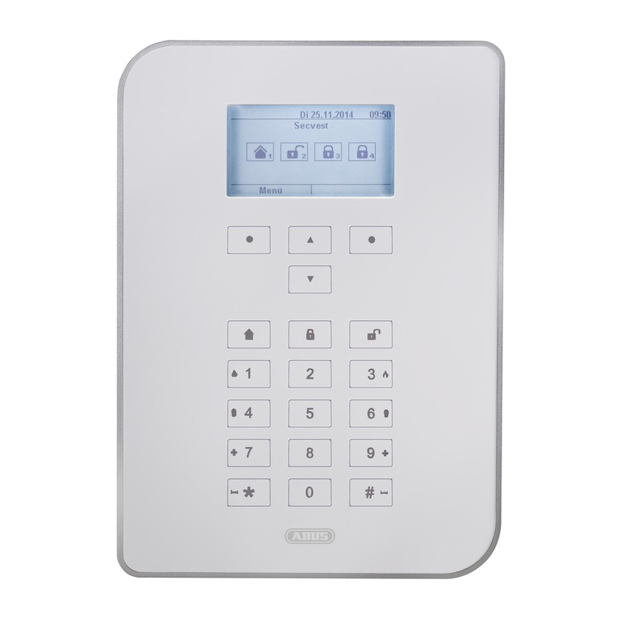
Page 17: Device Overview
Monitoring is deactivated (device disarmed). select options or to exit a menu Navigation buttons Proximity reader Used to navigate up/down Reader for the proximity keyfob. Hold the keyfob in front of the ABUS logo. Internal arm button Perimeter monitoring is activated (device armed internally). -
Page 18: International Key Assignment
Device overview International key assignment... -
Page 19: Device Rear (Mounting Plate)
Device overview Device rear (mounting plate) No. Name/function No. Name/function Mounting opening for screws Connection for LAN cable Housing tamper switch Connection for mains voltage 110 V/230 V AC 50/60 Hz Code reset PINs, see note below Micro SD card holder Connection for optional mobile wireless module Fuse holder for mains fuse Connection for ribbon cable... - Page 20 Device overview If you cannot go into installation mode, the alarm panel will sound a tampering alarm when you open the hous- ing. 2. Open the housing. Disconnect the entire power supply (mains voltage and batteries). Note: This procedure will not work if the tamper switch on the cover is closed. 3.
-
Page 21: Introduction
Introduction Introduction Terms and definitions Mobile wireless second generation standard, see GSM Alarm receiving centre, for details see EN 50518-1/2/3, EN 50136 and VdS 2471, see also ESCC Active intrusion protection Mobile wireless third generation standard, see UMTS Even an attempt to break in is reported. This can be done using alarm components that not only combine state-of- the-art wireless technology with effective mechanical in- Mobile wireless fourth generation standard, see LTE... - Page 22 Introduction Alarm transmission system User Perimeter protection Different users of the alarm system (e.g. owners, tenants) can be assigned separate rights and user codes. All points of access to the premises are monitored, in- cluding house doors, terrace doors, cellar doors, sky- User guidance lights and all windows.
- Page 23 Introduction CC/CV battery charging method The IU charging method, also known as CCCV for con- DD243 stant current constant voltage, combines the constant British requirement for sequential alarm confirmation. current charging method with the constant voltage charg- ing method. In the first phase of charging, a constant cur- DHCP rent that is limited by the charger is used for charging.
- Page 24 Introduction Double end of line (DEOL) Wiring version for wired alarm systems; wired zones also Intruder alarm system, burglar alarm system take on this configuration. Alarm system that detects an intrusion and triggers an Wired detector, wired detectors alarm. Alarm and danger detectors that are connected via wire Individual identification of detectors to the alarm panel.
- Page 25 Introduction Fast Format, FF Glass breakage detectors Protocol for transmitting data to an ARC/ESCC. DTMF- These detectors respond to breaking glass. There are based passive, active and acoustic glass break detectors. Remote access/remote configuration Danger alarm system Servicing/configuration of the alarm panel from outside of Alarm system that triggers an alarm for additional dan- the monitored premises (e.g.
- Page 26 Introduction Hybrid Module, HyMo, wireless additional module for the An Integrated Access Device (or router) is a device Secvest with wired zones and wired outputs. used for the network connection ports by the participant. HTTPS HyperText Transfer Protocol Secure, a communications IMEI protocol on the web, used to transfer data securely.
- Page 27 Introduction Jamming Combination sounder Interference that makes normal reception of wireless Combined sounder, e.g. siren (acoustic signal) + strobe emissions of electromagnetic waves difficult or impossi- (visual signal). ble. The source of interference sends out energy in the Communication options form of electromagnetic waves, just like the instruments Used to transmit alarm notifications using additional affected by the interference, which overlap the original...
- Page 28 Introduction Receiving centre See ARC The MAC address (Media Access Control, Ethernet ID) is the hardware address of every single network adaptor, Level 1–4 used to uniquely identify the device in the network. See access level 1-4 Medical emergency Line Personal medical emergency, for which help can be ar- Another term for zone, mainly used in wired areas.
- Page 29 Introduction Only enabled, a user or zone type that can be used only Open Circuit to activate the system. Opening detector A detector that identifies when a window, door, shutter, Normally Closed; contact or switch that opens when actu- garage door, etc. is opened. ated Normally Open;...
- Page 30 Introduction Perimeter surveillance Smoke alarm device Continuous monitoring of large areas of open land Optical smoke alarm devices save lives, as they respond around the periphery or the areas used for approaching to smoke particles in the air (usually poisonous gases). the property, e.g.
- Page 31 Introduction Germany: Bundesnetzagentur (BNetzA) – Federal Net- work Agency for Electricity, Gas, Telecommunications, Post and Railway Short Circuit Austria: the frequency use plan is published by the Fed- Tampering, tampering protection, sabotage eral Ministry for Traffic, Innovation and Technology So that the alarm panel and its components cannot be Switzerland: the frequency use plan is set out in the tampered with, each component is monitored for tamper- Swiss National Frequency Assignment Plan (NaFZ) and...
- Page 32 Introduction It is mainly used to send and forward email. Other spe- caught in the act, aggressive intruders are not provoked, cialised protocols such as POP3 or IMAP are used to re- etc.) trieve messages. Supervision SMTP servers use conventional connections to port 25 The alarm panel monitors whether detectors are present ("smtp").
- Page 33 Introduction Overlapping signal The Telekommunikations-Anschluss-Einheit (telecommu- See jamming. nications connection unit) is a type of connector used in Germany for telephone connections. Transmission equipment according to EN 50136 It is used as a connection to the public telephone network or as an a/b interface for analogue telephone connec- tions to additional devices.
- Page 34 Introduction Flood detector Verband der Schadensversicherer (German Association For detecting water damage and flooding, consisting of a of Insurers against Loss or Damage); defines guidelines basic device and water sensor. The sensor is always for different safety and security levels. mounted at a point where flooding would first start to in- cur water damage.
- Page 35 Introduction Certifications Inspection seal from an independent body that ensures the high quality and safety of alarm systems (in Germany the following are relevant: certification as per POS in ac- cordance with accident prevention regulations and VdS loss prevention) Zone Another term for a line.
-
Page 36: Alarm Panel Error And Tamper Monitoring
Introduction Alarm panel error and tamper monitoring The alarm panel continually monitors error and tamper states. The following is monitored: • Tamper contact: The alarm panel’s tamper contact is continually monitored. • Supervision The alarm panel continually monitors supervision messages from the components to the alarm panel. •... -
Page 37: Mounting/Installation
Mounting/Installation Mounting/Installation Connection overview, terminal block No. Name/function No. Name/function NO2, C2, NC2 – relay output 2: DC IN 13.8 V +: Connection for voltage supply 13.8 V potential-free relay contact, 30 V DC, 24 V AC rms, 500 mA OP3/4 –... - Page 38 Mounting/Installation TRB – trouble: Z301, Z302: wired zones 301 and 302 Fault indication input for the fault output of a wired sounder Note In the default settings, a jumper is connected to 0 V. This means there is no fault indication (fault) if no wired sounder is connected.
-
Page 39: Fixing The Mounting Plate To The Wall
Mounting/Installation Fixing the mounting plate to the wall Positioning the wireless alarm system (alarm Fixing the mounting plate panel) Danger Note The alarm panel is supplied power via an inte- grated power supply unit. The alarm panel should be positioned in a safe place out of sight of possible intruders and easily The power supply unitis connected to the build- ing’s 230 V AC grid via a separately secured line. -
Page 40: Connecting The Components
Mounting/Installation Important note: Note Place cables in such a way that none are crushed. During mounting ensure that the housing tamper switch (1) definitely has contact with the wall. Ensure that the bottom part and the integrated components are not damaged when the screws are tightened and that all screws are screwed in completely. -
Page 41: Installing The Micro Sd Card
Once the battery is connected, the system will start. Turn on the main power supply. Either plug the external power supply unit into the socket or turn on the circuit that provides the Secvest with 230V. Tip: By removing and reinserting the 230V main fuse within the Secvest, you can initiate an on/off of the 230V power supply. -
Page 42: Commissioning
Alternatively such faults. you can also use the ABUS IP Installer to display the • External D/C power supply error message for alarm panel and automatically access it. You can 13.8 V DC power supply. -
Page 43: For A System That Is Already Installed
Logging into the wireless alarm system After logging in, the software automatically asks the Open the web browser. ABUS FTP server: "Is new software available?" Enter the IP address in the following form: If the FTP server replies to this question with a "Yes", the xxx.xxx.xxx.xxx. -
Page 44: Logging Out From The Wireless Alarm System
Important! Automatic log out function: Based on the Secvest’s automatic log out function, this is now also possible on the web interface and Secvest app. • Installer or level 4 user is logged into the web in- terface. -
Page 45: Configuration
Configuration Configuration Notes Please consult the user guide for details on activating and deactivating the system, and on the behaviour of the alarm control panel and the display (user inter- face). The wireless alarm panel is configured in installer mode. There are two ways to configure the wireless alarm panel: •... -
Page 46: Menu Control Elements
Configuration Menu control elements No. Name/function No. Name/function Info bar Main menu list • Active main menu – here, "Info" with additional • The main menus are displayed submenus Button for online help Submenu list • Click this button to open the current documenta- •... -
Page 47: Login Screen
Configuration Login screen No. Name/function No. Name/function Input field for the user name Login button • Enter the Installer names. • The entry is case-sensitive. Input field for the password • Enter the Installer password. • Note for S/W <1.01.00 The default installer password is 9999(99). -
Page 48: Main Menu
Configuration Main menu No. Name/function Page No. Name/function Page INFO Outputs General information about: Overview/configuration of the outputs: • the alarm panel (software and hard- • Wireless outputs • Wired outputs ware version) • communications • HyMo outputs • the hybrid module •... - Page 49 Overview/configuration of the Virtual Secvest keypad. nursing emergency call The virtual keypad can be used to operate the system in exactly the same way as the keypad on the front of the Secvest device. Test Overview/Implementation of all possible test functions...
-
Page 50: Info
Configuration INFO Alarm panel S/W <2.00.00 Name/function Explanation Version Version number of the software currently installed on the alarm system Serial Number Serial number of the alarm system Part No Article number of the alarm system Language Version number for the configured language... - Page 51 Configuration S/W >= 2.01.08 Name/function Explanation Version, language Version number of the software currently installed on the alarm system Version number for the configured language Serial Number Serial number of the alarm system Part No.: Article number of the alarm system RF Device Exclusivity only new wireless components that have been on the market since 2015 can be added, e.g.
- Page 52 Configuration Partitions Number of partitions in use Outputs Overview of available and configured outputs Wireless outputs (WIRELESS), wired outputs of the alarm panel (WIRED), HyMo outputs (H/M) Housing Tamper Specifies whether the tamper contact on the front of the housing or the wall tamper contact has been triggered Sounder Tamper Specifies whether the tamper contact on the wired, connected siren has been trig-...
- Page 53 Configuration S/W >= 3.01.14...
-
Page 54: Communication
Configuration Communication... -
Page 55: Pstn
Configuration PSTN Name/function Explanation PSTN Link Status PSTN link status query. Secvest checks the connected telephone line. The message "OK" appears. If it is not connected, not enabled or is disrupted, the error message "Fault" ap- pears. -
Page 56: Ethernet
255.255.255.0. Gateway IP address If the Secvest is located on a network the IP address of the gateway is shown here. An example of a gateway in a private network is the router, e.g. the Fritz!Box. DNS primary IP address This is the IP address of the Domain Name System (DNS). -
Page 57: Mobile
Configuration Mobile Name/function Explanation Note These menus only appear when a wireless mobile module with an active SIM card is installed in the alarm panel SIERRA HL7692 Manufacturer and type of the fitted wireless mobile module Network Displays whether and how the SIM card is connected within the wireless mobile net- work. - Page 58 Configuration The value inside the brackets indicates the availability of the data connection. Availability of the data connection: 2G network only available, voice, no data possible “Without” GPRS network available. LTE/4G network available. (4G) IMEI International Mobile Station Equipment Identity (IMEI), a unique 15-digit serial num- ber that can be used to uniquely identify each wireless mobile end device.
-
Page 59: Hybrid Module
Configuration Hybrid module Name/function Explanation Number The internal number of the hybrid module Name The unique programmed name of the hybrid module Version The software version of the respective hybrid module... -
Page 60: Customisation
Configuration Customisation Name/function Explanation Please offer… -> ID of the wireless alarm system (required for the licence key) Please enter code Input field for the licence key for customisation of the alarm system (language set- tings, for example) Note The possibility of individual customisation via this menu is currently only intended for special appli- cations upon consultation with sales or support. -
Page 61: Status
Configuration Status No. Name/function No. Name/function Partition selection Status display Selection fields/tabs for individual partitions: The status display contains information including: • An alarm that is confirmed by the user but not re- • faults in the individual partitions • Faults across partitions set is displayed in the corresponding partition as a warning symbol. -
Page 62: Components
Configuration Components Teach-in via web interface... - Page 63 Configuration S/W >= 3.00.05...
- Page 64 Configuration S/W >= 3.01.14 Note From S/W 2.00.00 onwards, teach-in is possible via the web interface. To do this, simply click on an as yet unassigned zone, siren etc. The system will guide you through the teach-in process. Once teach-in is complete in the web inter- face, you must define the zone type.
- Page 65 Configuration Name/function Explanation Name Unique name of the zone Partition Partition of the individual zone Type Type of the individual wireless zone Attributes Overview of the attributes for the individual wireless zone...
-
Page 66: Detectors
Configuration Detectors IP zones Name/function Explanation Number The number comprises the zone name and the component type (IP). Name Unique name of the zone Partition Partition of the individual zone Type Type of the individual IP zone Attributes Overview of the attribute and status of the individual IP zone Note To integrate a network camera into a free IP zone, it must first be integrated and configured in the alarm panel network (see installation instructions TVIP41550 or IPCx Range). - Page 67 • Recordings (videos/pictures) from the IPCxyyyyyy cameras can only be called up via the camera’s web server or via the ABUS iDVR App (not via the alarm control panel log book) • URL/link to the camera in the log book for all events for which there are recordings available Add/delete Select the desired IP zone in the menu "Devices"...
- Page 68 Configuration Name/function Explanation Device Type Camera TVIP41550 IPCx Range Trigger Mode Internal TVIP41550 only The camera starts recording as soon as the integrated PIR sensor is triggered. External The camera starts taking pictures or recording video (IPCx range) as soon as one of the defined trigger events occurs on the alarm panel.
- Page 69 Configuration Camera Action IPCx range only Pictures and/or videos will be taken/recorded. Trigger Partitions (for "External" or "Int. + Ext." trigger mode only) Partitions to be monitored when trigger events occur. IP address IP address of the camera in the internal network Camera ports...
- Page 70 Configuration HTTP Port Internal HTTP port of the camera in the internal network (default setting: "80") HTTP Port External External HTTP port for which port forwarding in the router is configured RTSP port of the camera in the internal network (default setting: “554”) RTSP Port Internal RTSP Port External External RTSP port for which port forwarding in the router is configured...
- Page 71 This zone is used with lock switch contacts. Note This zone type was used in the Secvest 2WAY as a zone attribute rather than a zone type. Exit Norm Alm A zone configured as "Exit Norm Alm" behaves similarly to a "Normal Alarm" zone. A zone of this type, however, starts an alarm even when the detector is triggered during the exit time.
- Page 72 Configuration Type Explanation Perimeter Warn- This zone triggers a pre-alarm when the alarm system is armed or internally armed. The alarm panel beeps twice every five seconds. "Perimeter Warning" appears on the display every five sec- onds. Teach in outdoor motion detectors in this zone, for example. The wireless outdoor sirens flash and sound for approx.
- Page 73 Configuration Type Explanation The user cannot reset the system from a key switch zone. Key Switch A (latched) key switch can be connected to the alarm panel. A change to this zone changes the (Latched) status of the alarm panel from Enabled to Disarmed, or from Disarmed to Enabled (in accord- ance with the programmed output mode).
- Page 74 Configuration Type Explanation disabled when the wireless alarm panel is armed or disarmed. If the "Chime" attribute is assigned to this zone, the doorbell sounds both when the wireless alarm panel is armed and disarmed. Lock Set This zone is used to cancel the exit delay for a partition with the "Lock Set" attribute. This zone type is typically used for a switch (NO).
- Page 75 Configuration Type Explanation open but disabled on the control panel at the same time, the alarm panel may return to the "Set" status. Note With the zone attribute "Part Set" = ON A change to this zone changes the status of the alarm panel from Disarmed to Part Set (in accord- ance with the programmed output mode).
- Page 76 The user can acknowledge this warning and continue the arming process. A settings option for the partitions can be found in the section "Configuring Secvest via web server -> Partitions" Dis. Sabo- This attribute is an additional attribute for in this guide.
- Page 77 Configuration Part This zone is monitored when the partition of this zone or all partitions are internally Note armed. The Soak Test function should only be Activity The function of the detector is reversed set if a detector tends to trigger false Mon.
-
Page 78: Wireless Zones
Configuration Wireless Zones Name/function Explanation Number The number comprises the zone name and the component type (wireless/radio). Name Unique name of the zone Partition Partition of the individual zone Type Type of the individual wireless zone Attributes Overview of the attributes for the individual wireless zone Note Function Explanation... -
Page 79: Wired Zones
Configuration This display shows: confirmation of the teach-in process, because the • detector sends its signal more than once. the zones in which the detector has been taught In this case the message can be ignored. • the zone type configured for this detector •... - Page 80 Configuration Number The number comprises the zone name and the component type (wired). Name Unique name of the zone Partition Partition of the individual zone Type Type of the individual wired zone Attributes Overview of the attributes for the individual wired zone Note Delete All (alarm panel only) The description of the configuration of the zone...
-
Page 81: Hymo Zones
Configuration HyMo zones Name/function Explanation Number The number comprises the zone name and the component type (HyMo). Name Unique name of the zone Partition Partition of the individual zone Type Type of the individual HyMo wired zone Attributes Overview of the attributes for the individual HyMo wired zone... - Page 82 Configuration Note Delete All The description of the configuration of the zone Select Delete All. name, partition, zone type and zone attributes can Confirm the selection with Next. be found after the "IP zones" overview. Confirm the security prompt with Yes to delete the zone or select Back if you are not sure.
- Page 83 Configuration Note Zones Hybrid module 1 401 to 410 where 2-wire is chosen as the zone type 401 to 405 where 4-wire is chosen as the zone type Hybrid module 2 411 to 420 where 2-wire is chosen as the zone type 411 to 415 where 4-wire is chosen as the zone type...
-
Page 84: Wireless Control Panel
Configuration Wireless control panel Name/function Explanation Number The number comprises the component type (CDV) and a consecutive number. Name Unique name of the control device Partitions Assigned partitions of the individual control device Add wireless control panel Note Up to eight wireless control devices can be taught in. Select Add/Del Ctrl Device. - Page 85 Configuration Name/function Explanation Name Unique name of the control device Instant Set Immediate arming of the individually assigned partitions (yes/no) Partitions Assigned partitions of the control device C button || Action Selection of the action to be triggered when the "*" button is pressed: Not used C button has no function Arm the assigned partitions...
-
Page 86: External Sirens
Configuration External Sirens Wireless sirens Name/function Explanation Number The number comprises the component type (radio siren) and a consecutive num- ber. Name Unique name of the radio (wireless) siren Adding sirens Exit this display with Back. Select Radio Siren. Select edit Ext. siren. Select Add/Del Siren. -
Page 87: Wired Sirens
Configuration Wired Sirens Name/function Explanation Number The number comprises the component type (Wired SRN) and a consecutive num- ber. Name Unique name of the wired siren... -
Page 88: Indoor Sounder
Configuration Indoor sounder Name/function Explanation Number The number comprises the component type (indoor SG) and a consecutive number. Name Unique name of the indoor sounder (maximum 12 characters possible). By clicking on the respective indoor sounder, you will arrive at the “Add” mode. The Not added following course of action is the same as is described above for programming in the web interface. - Page 89 Configuration The following course of action is the same as is described for the alarm panel’s menu guidance below. Delete All Click on this field and in the next step confirm the security prompt to delete all in- door sounders. Remove Click on this field and in the next step confirm the security prompt to delete this in- door sounder.
- Page 90 Configuration Danger The settings in the user menu: User menu -> Configuration -> Volume Settings Operator Sounds Info tones: Alarm tones: also affect the volume of the tones of the indoor sounder. Note If the indoor sounder is operated by battery only, only alarm tones are sounded. No operation tones or info tones are sounded.
-
Page 91: Info Module/Indoor Siren
Configuration Info module/indoor siren Name/function Explanation Updates Enabled Status updates on the info module activated – a status change on the alarm system or zones is displayed "just in time". Deactivated No update on the info module and indoor siren – the indoor siren also does not trig- ger any alarm accordingly. - Page 92 Configuration...
-
Page 93: Wum (Wireless Universal Module)
Configuration WUM (Wireless Universal Module) Name/function Explanation Number The number comprises the component type (WAM) and a consecutive number. Name Unique name of the wireless universal module Adding a wireless universal module. Note Note Configure the universal module as describe in the WUM installation instructions, e.g. - Page 94 Configuration Select WAM Info. Note Select WAM 1. These outputs no longer have to be added manu- ally. Note Simply define the settings for the output function When the wireless universal module is taught in, as described in section Editing outputs. its configuration is also transferred, so it is possi- ble to see under "WAM Info"...
-
Page 95: Door Locks
Number The number comprises the component type (door lock) and a consecutive number. Name Unique name of the door locks (e.g. Secvest Key or additional door lock). Partitions Number of the partition to which the door lock is assigned. Note... -
Page 96: Rf Repeater
Configuration RF repeater Name/function Explanation Number The number comprises the component type (RF repeater) and a consecutive num- ber. Name Unique name of the repeater (maximum 12 characters possible). By clicking on the respective repeater, you will arrive at the “Add” mode. The follow- Not added ing course of action is the same as is described for the alarm panel’s menu guid- ance below. - Page 97 Configuration The following course of action is the same as is described for the alarm panel’s menu guidance below. Delete All Click on this field and in the next step confirm the security prompt to delete all re- peaters. When a repeater has been taught in, the wireless Add RF repeater (alarm panel) alarm panel beeps twice to confirm.
- Page 98 Configuration Exit the entry with Back. Note If a repeater has been taught in the symbol pears next to the repeater number on the alarm panel display. A maximum of 4 repeaters can be added Exit this display with Back. Edit Select the corresponding repeater.
- Page 99 Configuration Repeat detectors Select which hybrid module should be repeated. All hy- brid modules that have been learned in will be dis- Select which wireless zones/detectors should be re- played. peated by this repeater. All detectors that have been learned in will be displayed. Repeat wireless control panel Note Select which wireless control panel should be repeated.
-
Page 100: Hybrid Module
Configuration Hybrid module S/W >= 3.01.14 Name/function Explanation Number The number comprises the component type (hybrid module) and a consecutive number. Note A maximum of 2 hybrid modules can be added Name Unique name for the hybrid module (maximum 12 characters possible). By clicking on the respective hybrid module, you will arrive at the “Add”... - Page 101 Configuration The following course of action is the same as is described for the alarm panel’s menu guidance below. Delete All Click on this field and in the next step confirm the security prompt to delete all hy- brid modules with Yes. Select Back if you are not sure. Select the corresponding hybrid module.
- Page 102 Configuration Are selected in the HyMo Zones section. All availa- ble types and attributes for wired zones are Note possible. See IP Zones for details. It is possible to select a different type of wiring for the alarm panel and for each of the 2 hybrid modules. Hybrid module 1 401 to 410 where 2-wire is chosen as the Possible wiring types:...
- Page 103 Configuration If this input is controlled by the hybrid module, If this input is controlled by the hybrid module, the alarm panel signals the alarm panel signals "Hybrid Module X PSU Network Fault” "Hybrid Module X PSU Battery Fault” Note Hybrid module terminal LOW BATT...
-
Page 104: Outputs
Configuration Outputs S/W < 3.01.14 S/W >= 3.01.14... -
Page 105: Radio Outputs
Attributes of the radio output Configuring radio outputs Inverting outputs (polarity) Note Note Secvest has up to 32 radio outputs. You can choose here whether the function of the Editing outputs output in question is inverted or not. Select Nor- mal or Inverted. - Page 106 Configuration Type Explanation Can be assigned to partitions not used This output is not used and not activated at any time. Intruder alarm This output is activated when one of the following zone types or events is triggered and the system is armed: •...
- Page 107 Configuration Type Explanation Can be assigned to partitions HUA Confirm Timer This output is activated while the timer for confirmation of a hold up alarm is running and is deactivated as soon as the timer has expired. Duress Code A duress code has been used. The alarm panel activates the output as soon as a user enters a duress code and deactivates the output again when the user resets the system.
- Page 108 Configuration Type Explanation Can be assigned to partitions Alarm Abort The output is activated when an alarm is interrupted by the user in the selected partition during the possible time period. The output is deactivated as soon as the alarm is confirmed.
- Page 109 Configuration Type Explanation Can be assigned to partitions A/C fault The output is activated when the alarm panel does not have voltage OR any zone with type "Ext PSU A/C fault" is triggered. The delay until this output is activated depends on the value set under "System ->...
- Page 110 Configuration The system is VdS compliant if you use this output type for signalling an AC fault. This output type is now trig- gered after a VdS-compliant delay in the event of an AC fault. Fault comm. path The output is activated as soon as the alarm panel identi- fies a fault in the communication method and is deac- tivated when the fault no longer exists.
- Page 111 Configuration Type Explanation Can be assigned to partitions Complete arming This output is only activated when all of the partitions con- figured in the system are armed. Setting Complete This output is activated (for approx. 10 seconds) when the system or partition is armed or internally armed. Enabled This output is activated when the partition is armed.
- Page 112 Configuration Type Explanation Can be assigned to partitions Zone Omit (System) (Output only functions when confirmation mode DD243 or BS8243 is selected.) When there is an unconfirmed alarm the alarm panel re- arms when the confirmation time has expired. When the zone that triggered the unconfirmed alarm is still open at the time of rearming, the alarm panel omits this zone and activates this output.
-
Page 113: Wired Outputs
Configuration Type Explanation Can be assigned to partitions User Defined An output of this type can be controlled remotely via dif- ferent user-defined components such as remote control, control panel or alarm panel. The “Switch by user” and “configure by user” options grant the user permissions for the configuration of the out- put in the user menu view. -
Page 114: Configuring Wired Outputs
Configuring wired outputs Inverting outputs (polarity) Note Note Secvest has up to four wired outputs. You can choose here whether the function of the Editing outputs output in question is inverted or not. Select Nor- Click in the line of the desired output. -
Page 115: Hymo Outputs
Configuration HyMo outputs Name/function Explanation Number The number comprises the component type (HyMo output) and a consecutive num- ber. Name Unique name of the HyMo wired output. Type Type of the HyMo wired output. Status Current status of the HyMo wired output. -
Page 116: Configuring Hymo Wired Outputs
Configuration Configuring HyMo wired outputs Inverting outputs (polarity) Note Note Each hybrid module features four relay or wired outputs. You can choose here whether the function of the output in question is inverted or not. Select Nor- Editing outputs mal or Inverted. Click in the line of the desired output. - Page 117 Configuration Note Hybrid module outputs can be assigned to other partitions but they should be hybrid module partitions. Refer to the assignment of partitions for the hybrid module. Notifications from the hybrid module, such as tamper or DC fault notifications, are then assigned to these partitions. Note Outputs Hybrid module 1...
-
Page 118: Combination Outputs
Configuration Combination outputs A "combination output" is a virtual logical element within the alarm panel. It is similar to an AND-gate or OR-gate in digital electronics, but only exists within the configuration of the alarm panel. A "combination output" can have up to 10 inputs. A virtual input is an event such as a "burglar alarm" or a "panic alarm". - Page 119 Configuration You have set up "Combination output 1". You can use this to enable "Wireless output 203" on the alarm panel. Assign "Combination output 1" as the type for "Wireless output 203". You have to select one mode for each "combination output". This mode can be ALL (AND) or ANY (OR). For the AND mode, all inputs of the "combination output"...
-
Page 120: Partitions
Configuration Partitions Name/function Explanation Index List of partitions Partition 1 to partition 4 and full set link Name Name of the partition assigned during configuration. The selected partitions appear in the "Full set link" line Full set link Use this option to define a common partition. Partition 1 is always the common partition. -
Page 121: Configure Partitions
Configuration Configure partitions Please consult the user guide for details on activating and deactivating the system, and on the behaviour of the alarm control panel and the display (user interface). Choose a unique name for each partition, e.g. apartment, workshop, office (max. - Page 122 Configuration Name/function Explanation Exit Mode, Final Door Set • Use this option to complete arming of a partition by closing the last exit door. This cont. door has a detector with zone type "Final Door". When the door is closed, the par- tition is armed once the settle time has expired.
- Page 123 Configuration Name/function Explanation Exit Mode, Disarming the partition • The user unlocks the door and therefore activates the lock switch contact. cont. The "Lock Set" zone is opened. The alarm panel saves the activation of the "Lock Set" zone in the log book. The original "Final Door"...
- Page 124 Configuration Name/function Explanation Exit Time [s] This option only appears for modes "Timed Set" and "Silent Set". Time for the exit delay in seconds The exit time can be any value between 10 s and 120 s. Entry Time [s] Time for the entry delay in seconds The entry time can be any value between 10 s and 120 s.
- Page 125 Configuration The main purpose of the siren delay is to give communication with the ARC time and to be able to react from there, before the siren warns the intruder that the alarm has been triggered. The siren delay occurs when: Partition ->...
- Page 126 Configuration...
- Page 127 Configuration Name/function Explanation Ext. Siren Time [min] Time for the duration of the external siren(s) in minutes. The siren time can be set to a value between 0 and 15 min. If sounders are assigned to multiple partitions, the alarm panel uses the longest si- ren time set for the partitions in question.
- Page 128 Configuration Name/function Explanation Beep on Set After successfully arming the partition, there is one acoustic acknowledgement on the wireless external siren. "Siren" outputs are activated for 10 s after successfully arming the partition. After successfully arming the partition, there is no acoustic acknowledgement on the wireless external siren.
- Page 129 Configuration Name/function Explanation Note Siren time int. [min], When the entry delay is used, you would usually expect to hear the normal entry cont. tone. This entry tone should be heard as long as the entry delay is running. If you hear an alarm tone after opening the entrance door, you know immediately that the alarm panel has detected an intrusion during your absence.
-
Page 130: Configure Partitions
Configuration Configure partitions Part Set Name/function Explanation Name Unique name of the partition. The partition can be assigned an individual name here, e.g. apartment, workshop, office. Max. 12 characters are allowed. The alarm panel displays this name during arming. Part set Settings for the internal arming of the partition Select the mode of internal arming when exiting the premises. - Page 131 Configuration Name/function Explanation Exit Mode, Final Door Set • Use this option to complete internal arming of a partition by closing the last exit cont. door. This door has a detector with zone type "Final Door". When the door is closed, the partition is internally armed once the settle time has expired.
- Page 132 Configuration Name/function Explanation Disarming the partition Exit Mode, • The user unlocks the door and therefore activates the lock switch contact. The cont. "Lock Set" zone is opened. The alarm panel saves the activation of the "Lock Set" zone in the log book. The original "Final Door" zone which was converted into a "Normal Alarm"...
- Page 133 Configuration Name/function Explanation Settle time [s] This option only appears for modes "Final Door Set", "Lock Set" and "Exit Termi- nate". Use this option to define a time delay so that detectors can settle before the partition is internally armed. This may be necessary if detectors have triggered, send an alarm signal and have still not been reset.
- Page 134 Configuration Name/function Explanation Siren Delay [min] (ARC) Time for the delay duration of the siren(s). The siren delay can be set to a value between 0 and 10 min. When an alarm has been triggered the alarm panel waits until this time has expired before it activates the sirens.
- Page 135 Configuration Name/function Explanation Pt.Set Entry Route This option controls how an "Entry Route" zone is handled when the system is inter- nally armed. Entry Route • Every zone in this partition with type "Entry Route" and the attribute "Part Set" continues to function as an "Entry Route" zone. Final Door •...
- Page 136 Configuration Name/function Explanation Beep on Set After successfully internally arming the partition, there is one acoustic acknowl- edgement on the wireless external siren. "Siren" outputs are activated for 10 s after successfully arming the partition. After successfully internally arming the partition, there is no acoustic acknowledge- ment on the wireless external siren.
- Page 137 Configuration Name/function Explanation Siren time int. [min], Note cont. When the entry delay is used, you would usually expect to hear the normal entry tone. This entry tone should be heard as long as the entry delay is running. If you hear an alarm tone after opening the entrance door, you know immediately that the alarm panel has detected an intrusion during your absence.
-
Page 138: Configure Partitions
Configuration Configure partitions Deactivated Name/function Explanation Alarm Response Select the response here for when an alarm occurs in this partition. Internal • Alarm panel, indoor siren, info module and control device. Siren • Alarm panel, indoor siren, info module and control device. •... - Page 139 Configuration This does not affect the voice dialler, text message, email and push notification communication methods. Siren Delay [min] (ARC) Time for the delay duration of the siren(s). The siren delay can be set to a value between 0 and 10 min. When an alarm has been triggered the alarm panel waits until this time has expired before it activates the sirens.
- Page 140 Configuration Name/function Explanation Siren time Int. [min] Time for the duration of the internal siren(s) in minutes after a burglar alarm. The siren time can be set to a value between 0 and 20 min. If sounders are assigned to multiple partitions, the alarm panel uses the longest si- ren time set for the partitions in question.
-
Page 141: Configure Partitions
Configuration Configure partitions Panic response: Name/function Explanation Name Unique name of the partition Panic response: Select here the type of signalling used for a hold up alarm in the selected partition: Audible • When a hold up alarm is triggered, communication is sent and the acoustic alarm is sounded via the applicable sounders and the connected sirens (according to the set siren time). - Page 142 Configuration Name/function Explanation HUA response, Displayed • When a hold up alarm is triggered, communication is sent and the acoustic alarm cont. is sounded via the applicable sounders and the connected sirens (according to the set siren time). • The hold up alarm and details are shown on the alarm panel display. (No user code must be entered to view the details.) The acoustic warning is triggered on the alarm panel at the same time.
-
Page 143: System
Configuration System... -
Page 144: General
Language Only available on the alarm panel. Select the desired language with the desired version. Display Text Name shown on the Secvest display. Max. 20 characters From S/W 1.01.00 onwards, max. 16 characters (reason: compatibility with the ABUS server) Restore defaults Only available on the alarm panel. - Page 145 Configuration Note A reset • does not delete the log book You can select one or more of the following options: Note The default factory settings values are contained in the Appendix. Option Effect User Deletes all users, including their codes, proximity tags, remote controls, panic alarms, medical emergency transmitters and emergency call buttons.
- Page 146 Configuration Note Not reset in the “Configuration” user menu: • Activity monitor • Remote controls • Web Access • Level 4 updates • Time schedules enabled/disabled • Communica- Resets all options in the “Communication” menu. Specifically also the menu “Network -> Network Setup -> Web tion Server Blocked/Enabled”...
- Page 147 Configuration • UK • Switzerland • Italy • Austria • Spain • Ireland • Portugal • Norway • Netherlands • Denmark • France • Sweden • Belgium • Greece • Germany • Luxembourg Note Every country has different settings for PSTN communication and alarm reporting or the start and end of summer/winter time (daylight saving time).
- Page 148 • 2-wire CC Overview • IP address: 192.168.178.002 • DHCP: On • Version: v1.01.00 • S/N: SECVEST###E9000139AAE • Part No.: FUAA50000 Note Here you can see an overview of the most important data for the alarm panel. Login • Installer - Name (Web Server): <Installer names>...
- Page 149 Configuration Name/function Explanation (checkbox) Note Restoring the factory defaults: • deletes all taught-in and configured components, names and saved texts and numbers • does not delete the log book • does not delete the users with their codes and components •...
- Page 150 Configuration If the power supply is restored before the end of the set delay time, "General Fault" outputs are reset and a log book entry is created about the power restore. No errors are reported. If the fault still exists after the end of the configured time, a warning tone sounds and the error is reported.
- Page 151 Configuration Name/function Explanation (checkbox) Ext DC Fault Reporting Enabled Reports that a fault has occurred with the external DC power supply. Deactivated Function not possible. Ext DC Fault Delay Delay time in minutes (0–60 minutes) until the message is sent. (minutes) If a DC Fault occurs the alarm panel displays an error message after a few sec- onds, "General Fault"...
-
Page 152: Installer Details
Configuration Installer details Name/function Explanation Installer Name User name, number or character sequence used by the installer to log into the alarm system using a web browser. This entry is case-sensitive. Max. 12 characters Use a secure name. (See security tips) After the initial start-up please change the default installer name (code = name) to a secure user name. - Page 153 Configuration Installer Tel No The telephone number of the installer can be stored here for user reference in the event of a fault.
-
Page 154: User Access
Configuration User access Name/function Explanation (checkbox) Record Memo Enabled Allows the user to record a memo message. Menu -> Voice Memo Deactivated Function not possible. Dual Key Function Enabled Manual triggering of alarms is possible by simultaneously pressing the correspond- ing dual keys (fire alarm, hold up alarm, medical alarm) on the alarm system or con- trol device. - Page 155 Configuration Deactivated Function not possible. Social Care Key Enabled Manual triggering of a social care alarm is possible by simultaneously pressing the corresponding dual keys on the alarm system or control device. Danger S/W >= 2.01.08 You are using the touch front on the alarm system. The backlighting is set to “When active”...
- Page 156 The "Disarmed/No" setting only complies with BS8243 when the user has provided written consent. 2 Way Replies Enabled There is active status feedback from the wireless alarm system to the wireless re- mote control, wireless control device, Secvest key and additional door lock. Deactivated 2 Way Replies are deactivated.
- Page 157 Configuration Name/function Explanation (checkbox) Remote Inst. Set Use this option to decide whether the alarm panel is armed or internally armed after the remote control is operated. Enabled The possible partitions are armed or internally armed immediately. If an exit delay is configured, this is overridden and the alarm system is armed im- mediately as soon as the "arm"...
-
Page 158: User Reset
Configuration User Reset Name/function Explanation (checkbox) These menus determine the circumstances under which a user or installer can reset the system after an alarm or after tampering. Zone Alarms Enabled Allows the user to reset this alarm triggered for zones or detectors. Deactivated User cannot perform a reset. -
Page 159: Confirmation
Configuration Confirmation Name/function Explanation (checkbox) Conf. Mode Note Also follow the detailed information provided for the siren delay. This can be found under Siren Delay Partitions All Set. Note Confirmation mode functions only when alarm reaction is set to “Sirens and ESCC reporting”... - Page 160 Configuration Note: Confirmed panic alarm is not available in the basic confirma- tion mode. • DD243 • BS8243 Note The DD243 and BS8243 settings are only relevant for the UK (United Kingdom). When selecting these options, detailed knowledge of these guidelines is required. Sounder On Dropdown selection field for: •...
- Page 161 Configuration • 2 zones (DD243 only) (for confirmation modeDD243 • 1 zone and BS8243 only.) Confirmed Reset Dropdown selection field for: • Installer (for confirmation modeDD243 • User and BS8243 only.) Confirmation Time Panic Input field for the confirmation time for hold up alarms in hours. alarm (for confirmation mode BS8243 Note...
-
Page 162: Hardware
Configuration Hardware SW >= 2.00.00... - Page 163 Configuration Name/function Explanation (checkbox) Zone type (alarm panel) Dropdown selection field for: Wired Zone Type Use of inputs for wired zones • Don’t change • 2-wire FSL 2k2/4k7 • 2-wire FSL 1k/1k • 2-wire FSL 2k/2k • 2-wire FSL 4k7/4k7 •...
- Page 164 Configuration Name/function Explanation (checkbox) Only available on the alarm panel. SD Card Safely Remove Hardware • Any ongoing read or write operations are stopped properly. • The SD card can then be safely removed. Enable Hardware • After insertion, the SD card is brought into operation again. •...
-
Page 165: Security Settings
Configuration Security settings SW < 3.01.11 SW >= 3.01.11... - Page 166 Configuration...
- Page 167 Configuration Name/function Explanation (checkbox) 6 digit user code Note: From S/W 1.01.00 onwards, this menu item no longer exists. It is only possible to decide between 4 Digit User Codes and 6 Digit User Codes in the Start Wizard. It is no longer possible to change the length of the code once the wizard has been com- pleted.
- Page 168 Configuration When the numerical codes are reset (from 6 to 4 digits), all users and in- stallers are reset to their factory defaults (remote controls, chip keys, etc., are also deleted) Name/function Explanation (checkbox) RF Supervision Dropdown selection field for alarm system response for RF supervision If a wireless detector has had no contact with the alarm control panel for more than 20 min, the alarm panel creates a log entry: "RF warning".
- Page 169 Configuration Disabled No response No response • Log book entry of this • Log book entry of this event Fault • Display and warning tones event • No display and no warning tones • Tampering alarm • Tampering alarm Tamper Ac- •...
- Page 170 Configuration Name/function Explanation (checkbox) RF Jamming Dropdown selection field for alarm system response for jamming: The alarm panel can detect jamming of wireless signals. Corresponding processes are activated as follows: Alarm panel is armed Alarm panel is disarmed Disabled No response No response •...
- Page 171 Configuration If the Level 4 code is then used for accessing the alarm control panel, only the following menu options appear Level 4 User Name Level 4 User Code to allow the user to change the name and code. See "S/W Upgrade" appendix. You will find details about the S/W upgrade process there.
- Page 172 Configuration Name/function Explanation (checkbox) A user can be permitted to arm the alarm panel using the remote control even if one Force Set or more zones are not working or are open. Note If Force Set is enabled, the system is no longer compliant with EN 50131. Dropdown selection field for: •...
- Page 173 Configuration Name/function Explanation (checkbox) Ctrl Device Unset Full Set Select whether armed partitions can only be disarmed using the wireless control device when the delay time has been started beforehand ("Final Door" zone is trig- gered). Dropdown selection field for: •...
- Page 174 Configuration Name/function Explanation (checkbox) Silence Alerts This option controls the length of time in which warning tones (a brief "beep" every few minutes) are sounded. (silent warnings) Dropdown selection field for: • User Code • Warnings are sounded until a user enters their code to confirm the warning. •...
- Page 175 Configuration Enabled Additional delay (30 s) activated when deviating from the entry route. If a user deviates from the entry route within the entry delay time, the alarm panel waits 30 s before triggering a full alarm. Only an internal alarm is triggered first within these 30 s.
- Page 176 Configuration Name/function Explanation (checkbox) Broadcast Panel Status Enabled A status change to the alarm system is always transmitted to the wireless control device. The control device signals the status of the partitions, alarms and entry and exit delays "just in time". Deactivated The status of the alarm panel is only transmitted to the control device when queried ("?"...
-
Page 177: Panel Upgrade
The wireless alarm system must then be restarted. Details on upgrading the software to 1.01.00 can also be found in the "Software Upgrade" document in the Download area of the ABUS website. Note The "Panel Upgrade" menu is only available in this location up to S/W <1.01.00. From S/W 1.01.00 onwards, a new process has been established to ensure compliance with EN 50131. - Page 178 Configuration Only on the alarm panel Installer Mode -> System -> Upgrade alarm panel After pressing "Select", you will see a list of the available application software. The first row of this list contains the currently installed software, and the other rows the available software files that are saved on the SD card.
-
Page 179: Checking For An Upgrade
Name/function Explanation Checking for an upgrade? After pressing "Select", the alarm panel automatically asks the ABUS FTP server: "Is new software available?" If the FTP server replies to this question with a "Yes", the following note appears: "Upgrade available". -
Page 180: Backup/Restore
IDs). The backup file is saved in the default Downloads folder. Note The configuration file is saved in the format Secvest--01-09-2017-1051.cfg. If it has not been possible for the PC or web browser to perform the sent instructions... - Page 181 The alarm panel creates a new folder on the SD card with the name "Config". All of the configuration files are written to this folder. Each new file is given a new file name. No old files are overwritten. The alarm panel creates a file name that includes the Secvest, date and time. Example (SW 3.00.00 to SW < 3.01.00): Secvest--01-09-2017-1051.cfg...
-
Page 182: Report
Configuration Report SW >=3.00.01 Web interface only Name/function Explanation (checkbox) Report When clicking on the Report button, a pop-up browser window will appear. The window will display the entire system configuration for the alarm panel in a clear for- mat. Print To print the report, press the "Print"... - Page 183 Configuration Note Which printers appear will depend on the printers installed on the computer. E.g. "Real" paper printer, or "PDF printer" such as PDF-Xchange, Freepdf. Content of the report The report contains all relevant settings and information from the installer mode as well as the volume settings from the user menu.
-
Page 184: Communication
Configuration Communication Network... -
Page 185: Network Setup
To do this, log out of Installer mode and reboot the alarm panel. More details can be found in the section “Manual restart (switching off and switching back on)”. DHCP Enabled The Secvest receives the IP data from the DHCP server. Deactivated Manual input of IP data. IP address IP address S/W <2.00.00: If nothing is entered here, the alarm control panel automatically uses... - Page 186 We recommend assigning a fixed IP address to prevent problems with port route- ing. It is possible to set the router so that the Secvest always assigns the same IP address via DHCP for this MAC Address. However, some routers assign a different IP address via DHCP after a certain time.
-
Page 187: Ip Mobile Setup
Configuration IP Mobile Setup Name/function Explanation (checkbox) Note APN, user name and password are access data for IP-based transmission in the wireless mobile network. This data depends on the network provider and service provider. Request this data from your SIM card provider. Alternative: This data is usually stored on the SIM card. - Page 188 For cameras in the local network Note Danger If the “IP mobile” transmission path is used by the control panel, the ABUS server is not updated. Note The alarm panel receives a public IP address from the mobile IP network of the wireless mobile network.
- Page 189 For cameras in the local network It is not possible to access the alarm panel with the app via the ABUS server and via IP mobile. It is not possible to access the web server of the alarm panel via IP mobile.
- Page 190 For cameras in the local network It is not possible to access the alarm panel with the app via the ABUS server and via IP mobile. It is not possible to access the web server of the alarm panel via IP mobile.
- Page 191 For cameras in the local network It is not possible to access the alarm panel with the app via the ABUS server and via IP mobile. It is not possible to access the web server of the alarm panel via IP mobile.
-
Page 192: Email Setup
Configuration Email setup Name/function Explanation (checkbox) Max. charac- ters Server Name SMTP server name of the email service provider. IP Port Number IP port number Account Name of the email account (usually the email address) User name User name (depending on the provider, either the entire email address or a separate user name) Password Password for the email account... - Page 193 Configuration...
-
Page 194: Voip Dialler Setup
Configuration VoIP dialler setup Name/function Explanation (checkbox) Max. charac- ters SIP domain name SIP server name of the individual SIP service provider e.g. sipgate.de SIP proxy Proxy of the individual SIP service provider e.g. sipgate.de SIP User ID User ID of the SIP service provider for your account SIP User Password SIP user password of the SIP service provider for your account SIP Port... - Page 195 Configuration sipgate.de is the individual SIP service provider, as SIP server name ID, if the recipient has an account with the same SIP service pro- vider 9876543@sipgate.de SIP Dialler Enable Enabled The SIP dialler is enabled. Note The alarm panel does not send information. A connection is only estab- lished when a call is definitely made, starting with a handshake.
-
Page 196: Arc Reporting
Configuration ARC reporting... - Page 197 Configuration S/W >= 3.00.03 Name/function Explanation (checkbox) Call Mode Dropdown selection field for: • Disabled • Single • Alternate Note The alarm panel does not send information. A connection is only established when there is concrete ESCC reporting, starting with a handshake. The information is then sent in accordance with the settings (e.g.
- Page 198 Configuration • Ex SIA 3 v3 • Contact ID in SMS Note A detailed description of the protocol formats can be found in the Appendix "ARC (ESCC) reporting protocol formats"...
-
Page 199: Arc Reporting, Phone Book
Configuration ARC Reporting, Phone Book Name/function Explanation (checkbox) Tel Recipient # After clicking this field, the recipients that are stored in the phone book (contacts) appear. Select a recipient and their corresponding telephone number. IP recipient # After clicking this field, the recipients that are stored in the phone book (contacts) appear. - Page 200 Configuration Note Contacts/recipients that are used for monitoring station switching are no longer "visible" in the user menu’s phone book. As a result of EN 50131 compliance, Level 2 users (access level 2) must not make any changes to the monitoring station switching.
-
Page 201: Arc Reporting, Account Numbers
Configuration ARC Reporting, Account Numbers Name/function Explanation (checkbox) Account No P# Input field for an account number with up to 6 digits for the partition in question. CID uses 4-digit account numbers With Fast Format, you can use 4, 5 or 6-digit account numbers. The alarm panel adds a leading zero to lengthen 5-digit account numbers into 6- digit codes. -
Page 202: Arc Reporting, Fast Fmt Channels (For "Fast Format" Protocol Only)
Configuration ARC Reporting, Fast Fmt Channels (for "Fast Format" protocol only) Name/function Explanation (checkbox) Channel 1 to 8 Dropdown selection field for: • Not Used • Medical Alarm • Intruder alarm • Key Box • Conf. Intruder alarm • Tamper Activated •... -
Page 203: Arc Reporting, Cid/Sia Triggers (For All Protocols Except "Fast Format")
Configuration ARC Reporting, CID/SIA Triggers (for all protocols EXCEPT "Fast Format") Name/function Explanation (checkbox) Fire Enabled Medical Alarm Events from this group are transmitted to the ARC/ESCC. Technical Alarm Set/Unset Deactivated Reset No events from this group are transmitted to the ARC/ESCC. Omit RF Supervision RF Battery/PSU... - Page 204 Configuration Panel Battery Faults User Code Chnge Camera supervision...
-
Page 205: Encryption
Configuration Encryption From S/W v3.00.03 onwards, the message transmission to ARC/ESCC can also be encrypted. Note This is where the provisions of the following document apply. ANSI/SIA DC-09-2013: Internet Protocol Event Reporting SIA Digital Communication Standard – Internet Protocol Event Reporting For further details, see the "ARC/ESCC reporting"... - Page 206 Configuration Select the desired key length To input the key, click on "Edit key" Name/function Explanation (checkbox) Encryption length None Key length 128 bits 192 bits 256 bits None The messages are sent unencrypted 128 bits Note Enter the 32 hexadecimal characters as a key here. Hexadecimal characters are 0–9 and a–f...
- Page 207 Configuration 192 bits Note Enter the 48 hexadecimal characters as a key here. Hexadecimal characters are 0–9 and a–f...
- Page 208 Configuration 256 bits Note Enter the 64 hexadecimal characters as a key here. Hexadecimal characters are 0–9 and a–f...
- Page 209 Configuration On the alarm panel you will find the encryption settings under: Installer Mode -> Communications -> ESCC Reporting -> Recipient -> IP Recipient 1/2 Receiver IP Port Number Key length None 128 bit 192 bit 256 bit Note The menu item does not appear when "None" is selected for the key length. 128 bit has been selected as the key length.
- Page 210 Configuration 0000 0000 0000 0000 Note Enter the 32 hexadecimal characters as a key here. Hexadecimal characters are 0–9 and a–f 192 bit has been selected as the key length. 0000 0000 0000 0000 0000 0000 0000 0000 0000 0000 0000 0000 Note Enter the 48 hexadecimal characters as a key here.
-
Page 211: Arc Reporting, More
Configuration ARC Reporting, More Name/function Explanation (checkbox) Restorals If an event occurs that should be reported to the ARC, two bits of information are transmitted to the ARC: • Type and time of the event taking place • Event reset The event reset is called a "restoral". - Page 212 Configuration Unset Comms Enabled The alarm system transmits all status messages to the ARC, regardless of whether the system is armed or disarmed. Deactivated The alarm system transmits tamper, network failure and other status messages to the ARC while it is armed. When disarmed, the status messages are not transmitted to the ARC.
- Page 213 Configuration Note means classic voice transmission (also DTMF and FSK) or SMS transmission via a wireless mobile network. Note The display varies according to the setting via IP gateway the “IP Mobile Setup” menu. Stat. Auto Report Dropdown selection field for: •...
- Page 214 Configuration Name/function Explanation (checkbox) SET THE DAY Dropdown selection field for: • Sunday Only for "Static Test Call" • Weekly • Monday • Tuesday • Wednesday • Thursday • Friday • Saturday SET THE DAY Input field for the day of the month on which the test call should be carried out (1–31) Only for "Static Test Call"...
-
Page 215: Emergency Call
Configuration Emergency call Name/function Explanation (checkbox) Call Mode Dropdown selection field for: • Disabled • Single • Alternate Note The alarm panel does not send information. A connection is only established when an emergency call is actually sent, starting with a handshake. The information is then sent in accordance with the settings. - Page 216 Configuration S/W >=3.00.05 Set the order in which the communication methods should be used here. • PSTN 1, 2, 3 or No • Mobile 1, 2, 3 or No Note means classic voice transmission (also DTMF and FSK) via a wire- less mobile network.
-
Page 217: Social Care, Phone Book
Configuration Social Care, Phone Book Name/function Explanation (checkbox) Tel Recipients 1 to 2 After clicking in the selection field, a pop-up window appears, where the desired tel- ephone number of a recipient can be selected from the contacts in the phone book. Note S/W >= 3.01.11 If the alarm panel was unable to reach the respective recipient during the first dialling attempt, the alarm panel will at-... -
Page 218: Social Care, Account Numbers
Configuration Social Care, Account Numbers Name/function Explanation (checkbox) Account No P# Store an 8-digit account number (factory default = 00000000) for switching to a so- cial care alarm centre or alarm receiving centre for the partition in question. When reporting a social care alarm, the account number can comprise up to 8 dig- its. -
Page 219: Voice Dialler
Configuration Voice dialler S/W >=3.00.05... - Page 220 Configuration Name/function Explanation (checkbox) Enabled Enabled The speech dialler function is available. Deactivated The speech dialler function is not available. Note The alarm panel does not send information. A connection is only established when a call is definitely made, starting with a handshake. The information is then sent in accordance with the settings as well as the recorded voice messages for the events.
- Page 221 Configuration Note means classic voice transmission (also DTMF and FSK) via a wire- less mobile network. Note The display varies according to the setting via IP gateway the “IP Mobile Setup” menu Call Acknowledge Enabled The alarm transmission must be confirmed by the recipient with "5" or "9" Pressing DTMF button "5": calls to this number are ended.
- Page 222 Configuration...
-
Page 223: Speech Dialler, Triggers
Configuration Speech Dialler, Triggers Name/function Explanation (checkbox) Event Dropdown selection field for: • None • Intruder alarm • Panic alarm Use of panic alarms and user threat code • Fire • Medical Alarm • Social Care Alarm • Social Inactivity •... -
Page 224: Speech Dialler, Destinations
Configuration Speech Dialler, Destinations Name/function Explanation (checkbox) Receiver After clicking in the selection field, a pop-up window appears, where the desired tel- ephone number or SIP ID of a recipient can be selected from the contacts in the phone book. Note S/W >= 3.01.11 If the alarm panel was unable to reach the respective recipient during the first dialling attempt, the alarm panel will at-... -
Page 225: Speech Dialler, Test Call
Configuration Speech Dialler, Test Call Name/function Explanation (checkbox) Stat. Auto Report Static test call After clicking in a selection field, a pop-up window appears, where the desired rhythm can be selected. • Daily • Weekly • Monthly Note For each of the three types of call - daily, weekly and monthly - the alarm panel adds a random minute value. - Page 226 Configuration Note It is important to record a “test call” voice message in order to differentiate clearly this test call from a normal alarm call. Hour Input field for the time of the daily test call (format: h or hh) (0 –...
-
Page 227: Sms
Configuration Name/function Explanation (checkbox) Enabled Enabled The SMS function is available. Deactivated The SMS function is not available. Note The alarm panel does not send information. A connection is only established when an SMS is actually sent, starting with a handshake. The information is then sent in accordance with the settings as well as the programmed texts and events. - Page 228 Configuration S/W >=3.00.05 Set the order in which the communication methods should be used here. • PSTN 1, 2, 3 or No • Mobile 1, 2, 3 or No Note means classic SMS transmission via a wireless mobile network. Note The display varies according to the setting via IP gateway the “IP Mobile Setup”...
-
Page 229: Sms, Triggers
Configuration SMS, Triggers Name/function Explanation (checkbox) Message # After clicking in a selection field, a pop-up window appears, where the desired trig- ger for message 1 to 4 can be selected: • Tampers • Alarms • Set/Unset • System • Auto Report Note Note the settings during the test call:... -
Page 230: Sms, Destinations
Configuration SMS, Destinations SW >= 3.01.01 Name/function Explanation (checkbox) Message # After clicking in the selection field, a pop-up window appears, where the desired tel- ephone number of a recipient can be selected from the contacts in the phone book. Forwarding SW >= 3.01.01 Allows configuration of the alarm panel so that the SMS messages received by the... -
Page 231: Sms, Destinations, Message X
Configuration SMS, Destinations, Message X Name/function Explanation (checkbox) Tel Recipient # Selection of recipient 1 to 8 for message 1 to 4. Note S/W >= 3.01.11 If the alarm panel was unable to leave an SMS at the service centre for the respective recipient during the first dialling attempt, the alarm panel will attempt to reach the service centre for the respective recipient and leave an SMS a maxi- mum of three times. -
Page 232: Sms, Destinations, Forward
Configuration SMS, Destinations, Forward SW >= 3.01.01 Name/function Explanation (checkbox) Tel Recipient 1 Selection of a recipient for forwarding received SMS messages. -
Page 233: Sms, Destinations, Message, Telephone Recipients
Configuration SMS, Destinations, Message, Telephone Recipients Name/function Explanation (checkbox) None Do not select any recipients Receiver Select contact data for recipient A to L... -
Page 234: Sms, Messages
Configuration SMS, Messages Name/function Explanation (checkbox) Home Message Store a home message (max. 30 characters) Message # Store message 1 to 4 (max. 30 characters) -
Page 235: Sms, Pstn Sms
Configuration SMS, PSTN SMS Note It is possible to send SMS messages with many landline telephone connections. If you do not have an integrated wireless mobile module but want to send SMS messages over the The connection must be enabled for this, however, and PSTN line, you need to configure some additional all telecommunications equipment connected between data under this menu. - Page 236 Own Telephone No cept a processing request for an SMS message. (This is also used for clear invoic- ing of SMS messages.) Enter the Secvest landline number here. Only available when one of the following UCP protocols has been selected in the dropdown menu: •...
-
Page 237: Sms, Test Call
Configuration SMS, test call Name/function Explanation (checkbox) Stat. Auto Report Static test call After clicking in a selection field, a pop-up window appears, where the desired rhythm can be selected. • Daily • Weekly • Monthly Note For each of the three types of call - daily, weekly and monthly - the alarm panel adds a random minute value. - Page 238 Configuration Hour Input field for the time of the daily test call (format: h or hh) (0 – 23) Note Only full hours are possible. Days Dropdown selection field for: • Sunday If “Stat. Test Call" • Weekly • Monday •...
-
Page 239: Email
Configuration Email Name/function Explanation (checkbox) Enabled Enabled The email function is available. Deactivated The email function is not available. Note The alarm panel does not send information. A connection is only established when an e-mail is definitely sent, starting with a handshake. The information is then sent in accordance with the settings (e.g. - Page 240 Configuration 4G (LTE) E-mail with photos in attachment In the GPRS network, the data rate is too low to transmit large volumes of data. Telecoms Priority Set the order in which the communication methods should be used here. • Ethernet 1, 2, 3 or No S/W >=3.00.05 Set the order in which the communication methods should be used here.
-
Page 241: Email, Triggers
Configuration Email, Triggers Name/function Explanation (checkbox) Message # After clicking in a selection field, a pop-up window appears, where the desired trig- ger for message 1 to 4 can be selected: • Tampers • Alarms • Set/Unset • System • Auto Report Note Note the settings during the test call:... -
Page 242: Email, Destinations
Configuration Email, Destinations Name/function Explanation (checkbox) Message # After clicking in the selection field, a pop-up window appears, where the desired email address of a recipient can be selected from the contacts in the phone book. -
Page 243: Email, Messages
Configuration Email, Messages Name/function Explanation (checkbox) Home Message Store a home message (max. 30 characters) Message # Store message 1 to 4 (max. 30 characters) -
Page 244: Email, Test Call
Configuration Email, test call Name/function Explanation (checkbox) Stat. Auto Report Static test call After clicking in a selection field, a pop-up window appears, where the desired rhythm can be selected. • Daily • Weekly • Monthly Note For each of the three types of call - daily, weekly and monthly - the alarm panel adds a random minute value. - Page 245 Configuration Hour Input field for the time of the daily test call (format: h or hh) (0 – 23) Note Only full hours are possible. Days Dropdown selection field for: • Sunday If “Stat. Test Call" • Weekly • Monday •...
-
Page 246: Communication Options
Select how Secvest responds if a fault occurs with the telephone connection: • Disabled Fault Response • Audible • Silent GSM Line Select how Secvest responds if a fault occurs with the wireless mobile connection: • Disabled Fault Response • Audible (only when wireless mobile mod- • Silent... - Page 247 Configuration Deactivated When this option is deactivated, the user can still always use the commands for the speech dialler but not for the remote control. Ethernet Line Time in seconds until the alarm system responds to a fault in the internet connec- Fault Delay tion.
- Page 248 Configuration configure the exchange access code before the actual service centre telephone number. Format of the telephone number: "0 0123 4567890". See also notes in the Contacts chapter. For this purpose, contacts must be saved with two telephone numbers.
- Page 249 Configuration Name/function Explanation (checkbox) Call-in Control Note For more information on the key combinations on the telephone and the corre- sponding functions, see Chapter 11.4 "Operation via telephone" in the user manual. Enabled When this option is activated, the user can call the alarm system remotely. After the user has sent an access code to the wireless alarm panel in order to iden- tify themselves, they can send commands using the telephone keypad.
-
Page 250: Contacts
Configuration Contacts Up to 12 recipients can be defined here, to whom mes- sages are sent. Click on a user in the recipient list to open their contact profile. Enter the corresponding details here. S/W <2.00.00... - Page 251 Configuration S/W >=2.00.00 The recipient can be assigned to partitions. This stipulates that the recipient will only receive a message when an event occurs in the specified partition. Note This assignment of partitions is only applicable to voice diallers, text messages and email, and not for ARC/ESCC con- nection.
- Page 252 Configuration Note Wireless control panel Double-key function for fire, intrusion, medical emergency and care alarms Events triggered by these components are transmitted to the recipient where the selected partition matches the as- signment of partitions for that control device. Note SIP User (User) ID Format S/W >=2.00.00...
- Page 253 Configuration S/W >=3.00.05 Name/function Explanation (checkbox) Voice/SMS/Email Events are selected for and assigned to the speech dialler, the sending of SMS and the sending of emails. Events may come from the following groups: • Tampers • Alarms • Set/Unset • System The selected events are only transmitted to this contact when: •...
- Page 254 Configuration Activated Events will be transmitted to this contact Events will not be transmitted to this contact Part set Events will be transmitted to this contact Events will not be transmitted to this contact Example 1 1=Yes, 2=Yes, 3=Yes, 4=Yes Partitions Disarmed=Yes, Armed=No, Part Set=No Voice/SMS/Email...
- Page 255 Configuration 1=Yes, 2=Yes, 3=No, 4=No Partitions Deactivated=Yes, Activated=No, Part Set=No Voice/SMS/Email Event Alarm panel has been opened (sabotaged). Partitions 1 and 2 are Please note: Partitions 3 and 4 are not in use. Activated No voice call, no SMS, no email to this contact...
-
Page 256: Emergency Call
Configuration Emergency call Name/function Explanation (checkbox) Start Monitoring Hr Start time of social care monitoring (hh:mm). End Monitoring Hr End time of social care monitoring (hh:mm). Monitoring Interval Interval in hours. Language Volume Volume of voice announcement. -
Page 257: Test
Configuration Test Select the corresponding function. An overview of the different functions can be found in the table below. Via web interface with S/W >=2.00.00. SW >= 3.01.01... - Page 258 Configuration...
- Page 259 Configuration S/W >= 3.01.14 Note Test call to external recipients. Please inform them in advance and let them know that it is just a test call. Test call e.g. receiving centre, language call, SMS, email.
- Page 260 Configuration Function Meaning Walk Test Bell • On: An info tone sounds when a detector is operated. • Off: No info tone sounds. All detectors belonging to the system can be tested here. The zones can be individually selected during test.
- Page 261 Configuration Function Meaning Keypad Testing the keypad is possible both on the alarm panel and the web interface. Press all buttons on the keypad one after the other. The corresponding character or button function is shown on the display in response. Press the dual keys (fire alarm, hold up alarm, medical emergency or social care alarm) at the same time to test them.
- Page 262 Configuration...
- Page 263 Configuration Function Meaning Wireless Testing of wireless control panels is carried out in the web interface in the same manner as on the alarm control panel. panel Press the function buttons on the wireless control device one after the other. Wait 2 to 3 seconds between each button so that the control device can send each message.
- Page 264 To ensure good wireless communication, you must have a signal strength greater than 3. During the test, the reception power of the wireless alarm panel is reduced by 6 dB. The Secvest wireless alarm panel is sensitive to approx. -110 dBm at a signal-to-noise ratio of 12 dB.
- Page 265 Configuration Alarm panel # key Press this key to delete the recorded signal strengths for the selected component. * key Press this key to delete the recorded signal strengths for the entire list. Signal Detectors strengths The display shows the signal strength of each taught-in detector. (cont.) S/W <2.00.00 The zone names are displayed.
- Page 266 Configuration RF repeater (only alarm panel) The display shows the signal strength of each taught-in RF repeater. Under RF repeater below you will find clarifications for the display on the WEB. RF repeater components (only alarm panel) Under RF repeater below you will find clarifications for the display on the WEB. The display shows the signal strength of each assigned component to each RF repeater on the RF re- peater.
- Page 267 Testing of chip keys is carried out in the web interface in the same manner as on the alarm panel. Move the Prox Tag across the reader area at the bottom of the alarm panel (where the ABUS logo is).
- Page 268 Configuration Function Meaning Emer- Testing of the remote control is carried out in the web interface in the same manner as on the alarm gency but- panel. tons Press the button on a pendant. The following information appears on the display •...
- Page 269 Configuration Function Meaning Emer- Testing of the nursing emergency call function is carried out in the web interface in the same manner as gency call on the alarm panel. Nursing emergency call must be activated and the contact must be saved in the phone book. Installer Mode->Communications->ARC Reporting ->Call Mode ->Single (or Alternate) A list of the available connected transmission paths can be seen:...
- Page 270 Configuration Function Meaning Voice dial- Speech Dialler must be activated. Installer Mode->Communications->Speech Dialler->Call Mode->Enabled A list of the available connected transmission paths can be seen: Ethernet • Once this has been selected, enter a valid SIP User ID. • e.g. +498207123456789@sipgate.de •...
- Page 271 Configuration • When this is selected, the possible configured recipients are displayed with their contact names as stored in the phone book. • Scroll to the desired contact. Press the "Select” or “Start” key in the web interface. • The alarm panel sends a test text message to this recipient. GSM / Mobile •...
- Page 272 Configuration Function Meaning Zone Re- The current resistances for the wired zones (alarm panel and hybrid module) are displayed here. sistances Display on the alarm panel: The zone names are displayed. To view the zone numbers, press the right menu key. Test all variants according to the type of wiring to determine whether they meet the requirements: •...
- Page 273 Configuration • Ext. DC voltage in 14.1 volts • Panel Battery 1 8.3 volts • Panel Battery 2 0.1 volt • Aux. Voltage Out 13.9 volts HyMo PSU Here you can see the voltage value of the external DC power source at the terminal connection 0 V / 12 V IN of the hybrid module.
- Page 274 Configuration Click on the line of the desired repeater. The following display then appears: S/W < v3.01.14...
- Page 275 Configuration S/W >= v3.01.14 Click on the desired component type. Details on the signal strength display can be found above under Test -> Signal Strengths. Repeat alarm panel Here you can find 2 displays RF repeater This is the signal strength of the repeater to the alarm panel. Repeat alarm panel This is the signal strength of the alarm panel on the repeater.
- Page 276 Configuration Repeat detectors You can find the signal strength of the received messages from the detectors on the repeater here. Repeat wireless control panel You can find the signal strength of the received messages from the wireless control panel on the re- peater here.
- Page 277 Configuration Repeat outdoor sirens You can find the signal strength of the received messages from the external sirens on the repeater here. Repeat indoor sounder You can find the signal strengths of the received messages from the indoor sounders on the repeater here.
-
Page 278: Log
Configuration S/W <= v2.01.08... - Page 279 Configuration S/W >= v3.00.03 You can view the "log book" in this menu. Follow the instructions in the text conversion wizard to specify how the text will be divided into columns. The log book contains all of the relevant data for the alarm panel including the date and time.
- Page 280 … … The first 4 rows contain information about the alarm panel. The next rows mirror the content of the log book. Example: Secvest-ABUS, (display text) Secvest 3.01.11, Alarm panel time 11:39, date: 08/11/2018, The system is configured as: Partitions,...
-
Page 281: Virtual Keypad
Configuration Virtual keypad The virtual keypad has all the functionality of the keypad Note the following: and display of the alarm panel. If you are logged in as an installer on the web server, you On the alarm panel you press the corresponding buttons. open the virtual keypad in installer mode after entering an On the virtual keypad, you click the corresponding but- installer code. -
Page 282: Appendix
External cleaning work can be carried out by the user. Capacity Zones IP zones 6 (S/W 1.01.00 and later) for the ABUS camera models specified see the appendix to the instructions for installers entitled "Compatible equip- ment" Wireless Zones Wired Zones... - Page 283 Appendix Number of components per repeater Remote controls and emergency transmitters (intrusion, medical emergency, care alarm) are always repeated. Outputs IP Outputs Radio Outputs Wired Outputs Combination outputs Partitions Four (each with internal arming) User User names 50 (plus installer name) User Codes 50 (plus installer code) Proximity tags (chip keys)
- Page 284 Appendix 1 memo message (user menu) 30 seconds 58/56 zone names (user menu) 2 seconds for each zone 6 IP zones 48 wireless zones 4/2 wired zones Internal Siren 1 (integrated piezo sounder) Sound pressure level > 96 dB(A) @ 1 m Communication modules, plug-in Ports 1x Ethernet...
- Page 285 FUBE50061, FUBE50060, FU8165 Mechanical key differentiation 30,000 Door locks Additional door lock FUFT5001x-2x, 7010E 7025E Mechanical key differentiation 30,000 Secvest Key FUSK53030-58080, FUBE5XXXX Mechanical key differentiation 789,024 Web user name length 12 characters Web user name differentiation (215,671,155,821,681,003,462,656, 88^12, >1,000,000) All characters can be alphanumeric symbols or special symbols.
- Page 286 Type A with reference to EN 50131-1:2006+A1:2009 Section 9 and EN 50131-6:2008+A1:2014 Section 4.1 Secvest has an integrated power supply unit (Type A). This power supply unit supplies different internal voltages to the circuit board to supply power to the circuitry.
- Page 287 Appendix Running on DC input @13.0V 12.8 V max, idle 12.2 V min, full load (@ 600 mA) @13.8V 13.6 V max, idle 13.0 V min, full load (@ 600 mA) @14.5V 14.3 V max, idle 13.7 V min, full load (@ 600 mA) Note This output is not buffered by the battery in case of power failure.
- Page 288 Appendix Wireless signal transmission Operating frequency 868.6625 MHz In accordance with: EN 50131-5-3 Grade 2 EN 300 220-1 V.2.1.1 EN 300 220-2 V.2.1.1 EN 300 220-3 V.1.1.1 Frequency band reserved for applications in the security zone. Modulation Bandwidth +/- 10 kHz Narrow band, 25 kHz channel separation Transmission power...
- Page 289 Appendix Connections Mains connection 110 V/230 V AC, 50/60 Hz, (85-265 V AC, 50/60 Hz) L – line, single phase (black or brown) – protective earth (yellow/green) N – neutral (blue) - DC IN + External PSU input 13.8 V 13.8 V DC, external PSU at least 1.7 A See Power supply section for more details 0 V 12 V...
- Page 290 Appendix REN rating 1 PSTN data rates up to 1200 bps (V.22) Micro SD Secure Digital Memory Card Micro SD 11 mm x 15 mm x 1.0 mm 4 GB Micro SDHC Z301, Z302, Z303, Z304 Wired Zones 2-wire FSL 2K2/4K7 2-wire FSL 1K/1K 2-wire FSL 2K2/2K2 2-wire FSL 4K7/4K7...
- Page 291 LTE (4G) ESMO50000 2G GSM: 900 and 1800 MHz 4G LTE: B3 (1800 MHz), B8 (900 MHz), B20 (800 MHz) Communication methods Web server Web access, app and ABUS server ARC/ESCC reporting Receiver 2 Tel, 2 IP Protocols DTMF-based Fast Format, Contact ID...
- Page 292 Appendix Receiver PSTN SMS protocols TAP 8N1 TAP 7E1 UCP 8N1 UCP 7E1 ETSI Protocol 1 Email Receiver Remote control by telephone ATS Alarm transmission system The alarm panel contains an integrated SP2 (ATS2) communica- Categories and classifications tor to fulfil the requirements of EN 50131 for security level 2. ATS (Alarm Transmission System) categories, The alarm transmission system is compliant with EN 50136- SPT (Supervised Premises Transceiver) clas-...
- Page 293 2G fall back Remote Control by Phone 2G fall back 2G fall back E-mail (with photos) E-mail (without photos) Web server DynDNS ABUS Server SNTP (time synchronisation) IP camera Smartphone app Push messages Other Configuration Web browser via the integrated web server or directly on the alarm...
- Page 294 Security level: Level 2 Environmental class: Class II If the alarm panel has been installed correctly, the Secvest will be compliant with EN 50131 Grade 2. The Secvest is compliant with EN 50131-1 and EN 50130-5 environmental class II. Power supply is compliant with EN 50131-1:2006+A1 2009 Section 9 and EN 50131-6:2008+A1:2014 if the alarm panel has been installed correctly.
- Page 295 Appendix S/W >3.00.06 Option 1 Variant 2 TE Primary Network Interface Communicator mobile communication module, mo- bile radio module, cellular module, mobile service module, cellular mod- TE Replacement Network Interface mobile communication module, mo- Communicator bile radio module, cellular module, mobile service module, cellular mod- The alarm panel supports options A, B and C for grade 2 as given in Table 10 in EN 50131-1:2006+A1:2009 If the installer selects a non-compliant configuration the compliance label must be removed or corrected.
-
Page 296: Compatible Equipment
Appendix Compatible equipment Radio devices Name Article no Note Detectors Opening detector CC (brown) FUMK50000B Opening detector CC (white) FUMK50000W Opening detector FSL (brown) FUMK50010B Opening detector FSL (white) FUMK50010W Additional door lock with rotary knob 7010 E (brown) FUFT50010B Additional door lock with rotary knob 7010 E (silver) FUFT50010S Additional door lock with rotary knob 7010 E (white) - Page 297 Appendix Window handle lock FO 400 E – AL0125 (white) FUFT50051W Upgrade kit for FO 400 FUFT50058 PIR motion sensor FUBW50000 Motion detector (PET) FUBW50010 Outdoor motion detector FUBW50020 FUBW50021 FUBW50022 Smoke alarm device FURM50000 Glass breakage detectors FUGB50000 Shock detector FUEM50000 Flood detector FUWM50000...
- Page 298 Additional door lock with inner cylinder 7025 E (white) FUFT50021W Activate/deactivate (arm- with RC ing/disarming) S/W >= V2.00.06 Secvest key FUSK5xxxx Activate/deactivate (arm- ing/disarming) Secvest key with RC FUKE53030-58080 Activate/deactivate (arm- ing/disarming) S/W >= V2.00.06 RF repeater Repeater module Secvest FUMO50010 S/W >= V2.01.08 Hybrid Module...
- Page 299 Appendix Nursing emergency call transmitter Emergency buttons FUAT50000 Test devices Test box FU3801...
- Page 300 Appendix Wired components, accessories Name Article no Note Camera TVIP41550 PIR network camera TVIP41550 IP cameras Internal IP Dome IR 3MPx IPCA33500 S/W >= V1.01.00 IP Boxtype 2 MPx (1080p, 3 × WDR) IPCA52010 Universal IP Boxtype 3MPx IPCA53000 S/W >= V1.01.00 IP Boxtype 8 MPx (4K, 3 ×...
- Page 301 TVIP61550 IR HD 720p WLAN Network Outdoor Camera TVIP61560 Wi-Fi HD 720p Outdoor Camera TVIP62560 ABUS IP Video Surveillance 2 MPx Wi-Fi Mini Tube Cam- TVIP81000 Day/Night PTZ 720p Network Dome Camera TVIP81100 Day/Night PTZ 720p Network Outdoor Dome Camera...
- Page 302 Backup battery 7.4 V/2500 mAh FUBT50000 SD card Micro SD 4 GB storage card TVAC40970 4 GB Micro SDHC Touch Cover Individual Secvest Touch Cover FUZU50000 S/W >= 2.01.08 Wired components that fulfil the electrical specification of the corresponding connections (zones, outputs, inputs).
- Page 303 Appendix Software for operation, control and communication Name Article no Note Browser IE7 and older are NOT compatible Firefox Chrome Safari Secvest APP (iOS) APP50000 Version 2.1.1 2.1.0 2.0.1 1.3.5 1.3.1 1.2.5 1.2.2 1.1.7 1.1.2 iOS 10 or later iPhone, iPad, iPod touch...
-
Page 304: Hw Default Values/Factory Defaults
Appendix HW default values/factory defaults In the default settings, a jumper is connected between the TR (tamper return) connection and 0 V as well as the TRB (trouble) connection and 0 V. This means there is no fault indication (tamper/fault) if no wired sounder is connected. -
Page 305: Sw Default Values/Factory Defaults
SW default values/factory defaults Note The Secvest alarm control panel meets the requirements of EN50131 if the default values are retained while taking the note into account. If you change these settings, the installation may no longer be compliant. If the Secvest alarm control panel is no longer compliant with EN30131, you must remove all markings suggesting it is compliant. - Page 306 Appendix None Only appears if the zone type is not Partitions set to "Not Used". None Only appears if the zone was given Attributes a type that was not "Not Used". Some attributes are only available Part Set for certain zone types. Chime Soak Test Activity Mon.
- Page 307 Appendix Edit Zones Zone 40x Zone 401 to 420 Name Type Not used Partitions None Only appears if the zone type is not set to "Not Used". Attributes None Only appears if the zone was given a type that was not "Not Used". Some attributes are only available Part Set for certain zone types.
- Page 308 Appendix Indoor sirens/Info module Add Panel Updates Disabled Disabled Ready-to-Set LED Add/Del WAM WAM 01 to 08 WAM 0n Edit WAM Name WAM 0x WAM 01 to 08 Mode Delete All Door locks Add/Del Door Lock Door Lock 0n Door Lock 01 to 08 Edit Door Lock Name Door Lock 0x...
- Page 309 Appendix Add/delete Hybrid module 1 to 2 HyMo n Edit Name HyMo x Hybrid module 1 to 2 Partition 1-4: Partitions All partitions: Yes 2-wire FSL 2K2/4K7 Wired Zone Type Loudspeaker options Partition 1-4: Partitions All partitions: Yes Delete All 2.
- Page 310 Appendix 3. PARTITIONS Partition 1-4 Partition n Partition 1 to 4 Name Complete arming Timed Set Output Mode 40 seconds Only appears if the "Timed Set" or Exit Time "Silent Set" Output Mode is set. 15 seconds Only appears if the "Final Door Set", Settle Time "Lock Set"...
- Page 311 All partitions: No 4. SYSTEM General English This value depends on how you an- Language swer the language question during initial commissioning. Secvest Display Text Restore defaults Default settings Only appears as part of the factory- Country defaults default process. Mains Fault...
- Page 312 Appendix User Code Req’d This setting is required to fulfil EN 50131. EN 50131-1, Section 8.3.1 (with ref- erence to EN 50131-3, Section 8.3.1) 2 Way Replies Remote Inst. Set Switch to Yes for Duress Code use Duress Enable User Reset This option only appears if the con- Zone Alarms firmation mode is set to "Basic".
- Page 313 "V3.00.03 – Installed" Panel upgrade Once the selection has been made, Checking for an upgrade? the alarm panel automatically checks whether a new software ver- sion is available on the ABUS FTP server. Backup/restore Backing up config to the SD card "Secvest—04-12-2017-0932.cfg"...
- Page 314 S/W>=2.00.00 DHCP=off Empty This option will only be displayed, DNS primary IP ad- S/W <2.00.00 if an IP address is en- dress tered. S/W>=2.00.00 DHCP=off DYNDNS ABUS Server Status Enabled User name Empty Empty Password S/W <2.00.00 External Port...
- Page 315 Appendix Ethernet 2 Telecoms Priority PSTN 1 None Receiver Encryption None Account Numbers Account number for partition 1: One account number per partition 000000 Account number for partition 2: 000000 Account number for partition 3: 000000 Account number for partition 4: 000000 Channel 1: Fire Only appears if protocol = Fast For-...
- Page 316 Appendix Enabled Only appears if protocol = Fast For- Burg Comms Rearm mat AND if confirmation mode = "Basic" 800 ms Only appears if protocol = Fast For- 21CN Ack Time mat. Disabled Only appears if protocol = CID or Send Tamp As Burg SIA.
- Page 317 Appendix Event 1: None Message 4 Event 2: None Event 3: None Event 4: None Event 5: None Destinations None Call Acknowledge Enabled Month, day: 1, hour: 12:00 Stat. Auto Report Disabled Call Mode PSTN 1 Telecoms Priority Messages Empty Event None PSTN SMS...
- Page 318 Appendix Deactivated: Yes S/W >= 3.01.01 Voice /SMS/Email Activated: Yes Part set: Yes Empty Tel. no 1 Empty Tel No 2 Empty Email Empty IP address Empty SIP user ID 6. EMERGENCY CALL 08:00 (hh:mm) Start Monitoring Hr End Monitoring Hr 20:00 (hh:mm) 4 hours Monitoring Interval...
- Page 319 Appendix No Recipients! Only appears when a wireless mo- GSM/mobile bile module is installed. Comms not enabled Voice dialler Comms not enabled Email Comms not enabled Zone Resistances No Zones in use Panel PSU e.g. 14.2 volts Voltage value only appears if an ex- Ext.
- Page 320 Appendix MAC address IP Link Status Hybrid module No Devices!
-
Page 321: User Menu
Appendix User menu MENU option Default settings Comments Default values 1. USER Only visible to the administrator Add User Edit User Cannot be deleted "User 001" This value depends on how you an- Name swer the "Access Code Length" and "Administrator Code"... - Page 322 Appendix High Backlighting brightness LCD backlighting Backlighting for menu keys Backlighting for arm keys Backlighting for number keys Zone name announce- Maximum recording time = 2 sec- onds for each zone ment Enabled Recording Zone 101 to 106 IP zones Playback: None Delete Message...
- Page 323 Appendix Cleaning mode Date & time Only visible to the administrator SNTP Time sync. SNTP Time sync. Manual mode 01/01/2015 Set date 00:00 (hh:mm) Set time Automatic SUMMER/WINTER Edit Outputs Only visible to the administrator and only appears if the installer has set the outputs to "User Defined".
- Page 324 Appendix No Prox Tags learnt Prox Tag No Remotes Learnt Remote controls Emergency buttons No Pendants Learnt Telephone call Empty 8. LOG Only visible to the administrator 9. INFO Alarm panel Version Shows S/W version, S/N, Part No. and Language. Communication PSTN Only appears when a wireless mo-...
-
Page 325: Start Wizard
Appendix Start Wizard LANGUAGE UPGRADE PANEL APPLICATION COUNTRY DEFAULTS Set date Set time SUMMER/WINTER TIME Automatic (default setting) Manual A/C FAULT NOTIFICATION (default setting) EXT DC FAULT NOTIFICATION (default setting) BATTERY 2 WIRED ZONE TYPE WEB SERVER Disabled Released (default setting) DHCP If OFF is selected IP ADDRESS... -
Page 326: Acoustic Signal Tones
Appendix Acoustic signal tones The alarm panel is able to generate a wide range of acoustic signal tones. On components such as the control panel, indoor siren/info module, indoor sounder and loudspeaker on the hybrid module, these are similar to the alarm tones, info tones and operating sounds of the wireless alarm panel. - Page 327 Appendix The volume of the signal tones can be configured separately for each group. User menu -> Configuration -> Volume Settings Note Operator tones 0-10 Info tones 0-10 Alarm tones 0-10 These volume settings also affect the volume of the alarm panel and Note the indoor sounder and the loudspeaker on the hybrid module.
-
Page 328: Repairs And Maintenance
The alarm control panel should be checked once a year. During every inspection: • Check the Secvest for visible signs of damage on the housing or the front cover. • Check the condition of the housing-tampering switch and the wall-tampering switch (wall-removal contact) •... -
Page 329: S/W Upgrade
Important Saving and restoring the configuration As part of a comprehensive update, the Secvest wireless alarm system is reset to the factory defaults. It is therefore essential to save the alarm control panel configuration in advance: 1. "Installer Mode" web server 2. - Page 330 Appendix Important Changes have been made to the following menus as part of S/W 2.00.00 • VoIP Dialler Setup • Contacts -> SIP User ID • Outputs -> Type "User defined" • ARC/ESCC reporting -> IP port Please check these menus after carrying out the configuration and adjust the settings accordingly. Level4 updates Preparation: Adding new "Level 4 user"...
- Page 331 Appendix Starting the "Remote Update" procedure: Ensure that Alarm panel Installer Mode -> System -> Security -> Level4 Updates -> Enabled User Menu -> Configuration -> Level4 Updates -> Enabled Installer Mode -> System -> Security Settings -> Level4 Updates -> Enabled (activated, ticked) User Menu ->...
- Page 332 Appendix SW >= 3.00.03 Note Click on this symbol to generate a PDF version of the "Release notes" file. Click "Panel Upgrade"...
- Page 333 Appendix SW >= 3.00.03 Important Please ensure that you only load • a language file that is compatible with the existing application file or • a application file that is compatible with the existing language file or • a language file and an application file that are compatible with one another Please consult the corresponding release notes when doing so.
- Page 334 Appendix If they do not match, the web server warns the user that the alarm control panel will restart, their configuration will be lost and the Installer on Site will need to come to reconfigure the alarm control panel (the alarm control panel remains in "Start assistant").
- Page 335 Appendix...
- Page 336 Appendix Alarm panel User Menu -> Configuration -> Level4 Updates User Menu -> Configuration -> Security Settings -> Level4 Updates Blocked (deactivated – not ticked) A Level 4 user can only change the "Level 4 Code" and the "Level 4 User Name". Enabled (activated –...
- Page 337 Appendix Note This message will display: Network initialisation, please wait... Note You can tell an update process is running from the following 3 processes on the alarm panel. Menu keys light up Arm/disarm keys flash Number keys are dark Menu keys light up Arm/disarm keys are dark Number keys flash Menu keys are dark...
-
Page 338: Software Upgrade With New Files From The Ftp Server
Check for upgrade?". Log in to the web server as a Level 4 user. After logging in, the software automatically asks the ABUS FTP server: "Is new software available?" You can also start this process again manually. Click on "Check for upgrade?"... - Page 339 Appendix Note The current software comprises a new application file and language file. These files are stored on the SD card. Click on "Restart the alarm panel". The alarm panel installs the new files and performs a reboot. Important SW >= 3.00.06, saving and restoring the configuration Before the alarm panel starts the upgrade, the configuration files and the SSL certificate are saved automatically on the internal flash drive.
-
Page 340: Arc/Escc Reporting
Appendix ARC/ESCC reporting ARC/ESCC reporting protocol formats Note: To conform with EN50131, ARC (ESCC) reporting must be enabled. The alarm control panel automatically uses the classic protocols if the alarm control panel uses PSTN or GSM/wireless mobile as an outgoing communication path. Fast Format When using Fast Format, each message sent to the ARC (ESCC) consists of the following: 4, 5 or 6-digit account number. - Page 341 Appendix The only difference between this example and the first example is the event identifier of 3 to show a restore for the system tamper alarm and the checksum value. SIA 1, SIA 2, SIA 3, Extended SIA 3 and Extended SIA 3 V2 The SIA formats transmit data from the log book entries to the ARC (ESCC).
- Page 342 Appendix Some S/W versions that work in the SIA recipients do not always recognise the "/" text separator. This may cause problems. This incorrectly results in "mains fail" messages on the ARC (ESCC). This may occur when arming or dis- arming the alarm control panel or when entering or exiting the Installer Mode.
- Page 343 If it is not possible to send messages, it may be that the firewall has also blocked various outgoing ports. Therefore, check the firewall settings on the router/IAD. Information on implementation in the Secvest with reference to chapter 5.5.1 "Event Messages (PE)" of the CD-09 specification.
-
Page 344: Cid/Sia Events
Appendix CID/SIA Events This menu only appears if you select "Contact ID" or one of the SIA versions at the following point: Installer Mode -> Communication -> ARC Reporting -> Protocol A detailed description of the CID and SIA formats can be found in the "ARC (ESCC) reporting protocol formats" ap- pendix To simplify the programming, the possible CID/SIA events are assigned to corresponding groups. - Page 345 Appendix Table 1 CID codes – CID report groups CID code Contains: CID report group Medical alarm Medical Alarm Social Care (Social Emergency) Medical Alarm Fire Alarm and Fire Restore Fire Hold Up zone (Panic) and Restore Panic alarm Hold Up (Panic) silent and Restore Hold Up keypad (Panic) and Restore Hold Up RF (Panic) and Restore Hold Up wireless control panel (Panic) and Restore...
- Page 346 Appendix Hold Up zone component fault and Restore Faults IP zone camera supervision fault and ok Camera supervision e.g. IP zone missing, IP-zone timeout). Zone supervision fault and Restore RF Supervision Supervision wireless control panel fault and Restore External Siren supervision fault and Restore 1) WAM supervision fault and Restore Door Locks supervision fault and Restore Flat battery zone fault and Restore...
- Page 347 Appendix Table 2 CID report groups – CID codes CID report group CID code Contains: Fire Fire Alarm and Fire Restore Panic alarm Hold Up zone (Panic) and Restore Hold Up (Panic) silent and Restore Hold Up keypad (Panic) and Restore Hold Up RF (Panic) and Restore Hold Up wireless control panel (Panic) and Restore Panic alarm...
- Page 348 Appendix Omit User/system zone hidden, zone shown Key Box Key Box open and closed RF Supervision Zone supervision fault and Restore Supervision wireless control panel fault and Restore External Siren supervision fault and Restore 1) WAM supervision fault and Restore Door Locks supervision fault and Restore RF Jamming Jamming fault and Restore 1)
- Page 349 Appendix Manually triggering test report 2) Periodic/automatic test report 2) Note: 1) The alarm control panel communicates Jamming and Supervision if the system is disarmed. 2) Independent of a group/no reference to a group...
- Page 350 Appendix Table 3 SIA codes – SIA report groups SIA code Contains: SIA report group AT, AR Mains fail and Restore Mains Fault AT, AR External PSU AC fault and Restore Faults BA, BR Intrusion Alarm and Intrusion Restore Intruder alarm BA, BR Perimeter and Perimeter ok Intruder alarm...
- Page 351 Appendix PT, PJ Hold Up zone component fault and Restore Faults QA, QH Social Care (Social Emergency) Medical Alarm User codes reset to default User Code Chnge Periodic/automatic test report 2) Download successful Download Download failed Download Manually triggering test report 2) TA, TR Keypad tampering and Restore Tampers...
- Page 352 Appendix Table 4 SIA report groups – SIA codes SIA report group SIA code Contains: Fire FA, FR Fire Alarm and Fire Restore Panic alarm HA, HR Duress and Restore Panic alarm Hold Up (Panic) alarm acknowledged Panic alarm PA, PR Hold Up zone (Panic) and Restore Hold Up keypad (Panic) and Restore Hold Up RF (Panic) and Restore...
- Page 353 Appendix Exit Timeout Exit Timeout and Restore Omit BB, BU User/system zone hidden, zone shown Key Box BA, BR Key Box open and closed RF Supervision Zone supervision fault and Restore Supervision wireless control panel fault and Restore External Siren supervision fault and Restore 1) WAM supervision fault and Restore Door Locks supervision fault and Restore RF Jamming...
- Page 354 Appendix e.g. IP zone missing, IP-zone timeout). Download Download successful Download Download failed Periodic/automatic test report 2) Manually triggering test report 2) Note 1) The alarm control panel communicates Jamming and Supervision if the system is disarmed. 2) Independent of a group/no reference to a group...
-
Page 355: Email Error Messages
Appendix Email error messages The following table shows the SMTP server response codes: non standard success response, see RFC876 System status, or system help reply Help message <domain> service ready <domain> service closing transmission channel successful authentication Requested mail action OK, completed User not local, will forward to <forward-path>... -
Page 356: Tcp/Ip Error Messages
Appendix TCP/IP error messages The following table shows the TCP/IP error messages: 1001 General Error 1002 Invalid socket descriptor 1003 Invalid parameter 1004 It would have blocked 1005 Not enough memory in memory pool 1006 Connection is closed or aborted 1007 Socket is locked in RTX environment 1008... - Page 357 Appendix 40848 The peer notified us that the connection is going to be closed 40976 Processing of the ClientHello handshake message failed 41104 Processing of the ServerHello handshake message failed 41232 Processing of the Certificate handshake message failed 41360 Processing of the CertificateRequest handshake message failed 41488 Processing of the ServerKeyExchange handshake message failed 41616...
-
Page 358: Voip Error Messages
Appendix VoIP error messages The following table shows the user-relevant error messages: VOIP_CALL_NO_RESULT VOIP_CALL_FAIL_NO_LINK VOIP_CALL_FAIL_NO_LOCAL_ADDRESS VOIP_CALL_REJECTED VOIP_CALL_TIMEOUT_NO_ANSWER VOIP_CALL_CANCELLED VOIP_CALL_DECLINED VOIP_CALL_FORBIDDEN VOIP_CALL_NOT_FOUND VOIP_CALL_INIT_SIP_URL_ERROR VOIP_CALL_CALLER_ABORT VOIP_CALL_DISCONNECT VOIP_CALL_PASSWORD_ERROR VOIP_CALL_LINK_LOST_ERROR The following table shows the internal error messages: VOIP_CALL_INIT_PARAM_ERROR VOIP_CALL_PJSIP_APP_ERROR VOIP_CALL_ICE_CREATE_ERROR VOIP_CALL_ICE_PROCEDURE_ERROR VOIP_CALL_ICE_INVITE_CREATION_ERROR VOIP_CALL_ICE_REINVITE_CREATION_ERROR VOIP_CALL_ICE_REINVITE_SEND_ERROR VOIP_CALL_ICE_UPDATE_CREATION_ERROR VOIP_CALL_ICE_UPDATE_SEND_ERROR... -
Page 359: Gsm Cme / Cms Error Messages
Appendix GSM CME / CMS Error messages The following tables show the user-relevant error messages: CME Error codes GSM Equipment related codes Phone failure No connection to phone Phone-adapter link reserved Operation not allowed Operation not supported PH-SIM PIN required PH-FSIM PIN required PH-FSIM PUK required SIM not inserted... - Page 360 Appendix GPRS services not allowed PLMN not allowed Location area not allowed Roaming not allowed in this location area Service option not supported Requested service option not subscribed Service option temporarily out of order Unspecified GPRS error PDP authentication failure Invalid mobile class Alternate SIM conflict Operation temporarily not allowed...
-
Page 361: Cms Error Codes
Appendix HTTP header's name is an empty string HTTP header's value is an empty string Format of input data is invalid Content of input data is invalid or not supported The length of a parameter is invalid The format of a parameter is invalid CMS Error codes GSM Network related codes Unassigned (unallocated) number... - Page 362 Appendix No SMS storage capability in SIM Error in MS Memory capacity exceeded SIM Application Toolkit busy SIM data download error Unspecified error cause ME failure SMS service of ME reserved Operation not allowed Operation not supported Invalid PDU mode parameter Invalid text mode parameter SIM not inserted SIM PIN required...
-
Page 363: Log
Appendix Log book entries This appendix provides a short explanation of the messages that may appear in the alarm panel log. Please note that many of these messages refer to specific components with the respective component numbers. For this reason, it is not possible to show the exact log messages that you would see in a particular installation in this list. The list itself is in alphabetical order according to the message text. - Page 364 Appendix "== Chargr 2 Restore" Extension == battery 2 charger ok “== Load 1 OK” Extension == battery 1 load test OK "== Load 2 OK" Extension == battery 2 load test OK "== Load 1 Fail" Extension == load test for battery 1 failed "== Load 2 Fail"...
- Page 365 Appendix "Alarm CONF CDV==" Confirmed alarm wireless control panel == "Alarm CONF bell #" Confirmed alarm sounder# "Alarm sound generator" Confirmed alarm sound generator "Alarm CONF siren ==" Confirmed alarm siren == "Alarm CONF WAM ==" Confirmed alarm WAM == "AlarmCONF Z=="...
- Page 366 Appendix "U--- Shunt Code" Shunt code from user -- entered "U-- Spch Tel = Chg" User -- has changed a number on the speech dialler "U-- System Exit" User -- has started the exit delay "U--- Ptn ## Exit" User -- has activated the output delay in partition ## "U--- Ptn ## Duress Rstr"...
- Page 367 Appendix "Missing K==" Control panel == missing "Missing K== Restore" Control panel == is restored "U-- Ptn # Override" User -- has activated partition # despite warning "Care U-- Low Bat" Care alarm battery low "CO Z== Alarm" Carbon monoxide alarm zone == "CO Z== Restore"...
- Page 368 Appendix "Ext PSU Rstr Z==" Z== external power supply restore "Ext PSU Fail Z==" Z=== external power supply fault "Ext Volts Rst Z===" Z=== external power supply restore "Ext Volts Rstr Z==" Z== external power supply restore "External DC Fail" External failure in the direct current "Remote U-- Low Bat"...
- Page 369 Appendix "RSN== Tamper" Radio siren == tampering "RSN== Superv Fail" External siren == radio monitoring fault "RF Failure Restore" Radio frequency failure rectified "RF Failure" Radio frequency failure "Lid Tamper Restore" Tampering with alarm control panel housing has been reset "Panel lid open"...
- Page 370 Appendix "Medical Alarm" Medical emergency alarm triggered via control panel "Medical Restore P#" Medical alarm partition # restored "Medical Restore" Medical alarm has been restored "Medical K== Alarm" Medical emergency alarm via control panel == triggered "Detector Flt Z===" Zone === Terminal resistance fault "Det Restore Z==="...
- Page 371 Appendix "Bell Tamper" Sounder sabotage alarm "Key Box Open Z===" Key box open zone === "Key Box Close Z==" Key box closed zone === "Key Box Open Z==" Key box open zone === "Key Box Close Z==" Key box closed zone === "Lock Sab Rst Z==="...
- Page 372 Appendix "System Tamper" System Tamper triggered "System Rearmed" System was rearmed "System error" Fault in main processor of alarm control panel. Try restarting. The system has been restarted after a power failure (main power supply and "System start" battery). "Ptn # Remote Rst" Partition # has been reset by the remote control device "Tech Z== Alarm"...
- Page 373 Appendix "HUA Confirm ==" Hold up alarm confirmed via control panel == "HUA Confirm Aux #" Hold up alarm confirmed via external power supply to equipment # "HUA Confirm Aux" Hold up alarm confirmed via external power supply to the equipment "HUA Confirm CDV=="...
- Page 374 Appendix "WSN== Trouble" Wired sounder fault "Z== Follow Photos" Photos were recorded because zone === was triggered. "Z== PSU Rst" Zone == smoke detector power supply unit fault reset "Z== PSU Flt" Zone == smoke detector power supply unit fault "Z== Smoke PSU Rst"...
-
Page 375: User Numbers
IP Finder, ABUS IP installer This user number is recorded if the IP Finder application is used to find Secvest in the network. Name, IP address, type, status and MAC address can be determined with the IP Finder. ABUS server DDNS client This user number is recorded as part of the configuration change, while the assigned ID is received after the device is added to the ABUS server. - Page 376 Appendix This user number is recorded as part of the configuration change, while the assigned ID is received after the device is added to the ABUS server.
-
Page 377: Troubleshooting
Appendix Troubleshooting Manual restart (switching off and switching back on) S/W >=1.01.00 This is helpful for some problems, to reset the alarm panel to a defined initial state. All the settings and configurations are retained. Note A restart is only possible when all partitions are "disarmed"... - Page 378 Appendix Click on "Restart alarm panel". You are prompted for confirmation. Picture: Restart_alarm panel_2 Click on "Restart alarm panel" again. At this point you can still cancel the restart. Click on "Cancel restart". The restart is displayed as shown below. Picture: Restart_alarm panel_3...
- Page 379 Appendix After the restart you are automatically logged out of the web server. If you wish to continue working on the web server, please log in again with your user name and password. [3] Alarm control panel – "Up" and "Down" navigation keys Hold down the "Up"...
-
Page 380: Carry Out A Gsm/Wireless Mobile Manual Test Call, Prepaid
Appendix Carry out a GSM/wireless mobile manual test call, prepaid Danger Note If you use a prepaid SIM card on a prepaid tariff, e.g. CallYa, Xtra or MagentaMobil-Start Please carry out a GSM/wireless mobile test call and/or send a GSM/wireless mobile test text message every month or every three months. -
Page 381: Diagnostic Leds On The Motherboard And Gsm/Wireless Mobile Module
Flashing green, 1 Hz Normal operating status Secvest Update Utility in use: The "heartbeat" LED should be flashing quickly to show that the Secvest is currently working in "Update" mode. BOM: LED9 Y/G Internal power supply 3.3 V On green Internal power supply 3.3 V is OK. - Page 382 Appendix The system has "lifted the telephone receiver" for PSTN The system has "hung up the telephone receiver" for PSTN BOM: LED3 red RFTX RF transmitter status RF transmitter active RF transmitter not active BOM: LED4 red STATUS (GSM/wireless mobile mod- Status GSM/wireless mobile module ule) Sleep mode...
-
Page 383: Trace, Recording Communication Sequences
E.g. +CSQ: 14.99 14 = -85 dBm (Secvest display RSSI 4) Value range of up to 0-31 represents value range from Secvest 0-9 X = 1 = Email The communication protocol between the alarm control panel and the SMTP server. - Page 384 X = 4 = HTTPS client The communication protocol between the alarm control panel and the ABUS server. X = 5 = HTTPS server This view shows a snapshot recording every five seconds of the currently active HTTPS connections on the web server.
- Page 385 >ATDT*99***1H <CONNECT tone dialling X = 9 = Cloud Connection The communication protocol between the alarm control panel and the ABUS cloud. Example: >Panel ID: U0yVq7k….. X = 10 = System (S/W >= v3.01.01) 10 = Press the ▲ "Up" menu key This view displays system errors X = 11 = cameras (S/W >= v3.01.09)
-
Page 386: Router, Iad, Firewall
Appendix 11 = Press the ▼ "Down" menu key This view shows communication faults between the alarm panel and the cameras. Router, IAD, Firewall ARC/ESCC reporting and DC-09 Note The TCP internet protocol is used for the transmission. TCP uses port 9999. If it is not possible to send messages, it may be that the firewall has also blocked various outgoing ports. -
Page 387: Time Zones
Appendix Time zones A time zone is an area consisting of several countries and parts of larger countries in which the same officially- regulated time applies. The zone time indicates the difference between the local time and UTC (Coordinated Universal Time), otherwise known as GMT (Greenwich Mean Time). -
Page 388: Landline Notification Centre
Appendix Landline notification centre Germany F-SMSC operator Protocol Service Centre Tel. Materna UCP 8N1 09003 266 9002 Telekom 01930105 Additional information can be found here: Materna http://www.sms-im-festnetz.de/sms/ Telekom http://hilfe.telekom.de/hsp/cms/con- tent/HSP/de/12556/Startseite/SMS;jsessionid=1620596013AB81A8BADD3E34609A213F http://hilfe.telekom.de/hsp/cms/content/HSP/de/12538... -
Page 389: Gsm Network Notification Centre
Appendix GSM network notification centre In order to send a text message (SMS) to a predefined Note telephone number if an event occurs, the number of the For detailed information please contact SMS service centre must be stored on the SIM card. your mobile phone network provider. -
Page 390: Email Notification/Email Setup
This section provides an overview of the email provid- email address if an event occurs, the SMTP login data ers that offer their services free of charge. • GMX for the email account must be stored in the Secvest. • web.de Note • Yahoo The SMTP functionality is not available free of •... - Page 391 Appendix Googlemail Server Name smtp.gmail.com Server IP port number 25 or 587 Account <email address> e.g. yourname@gmail.com User name <email address> e.g. yourname@gmail.com Password <password for email account> Disabled T-Online Server Name securesmtp.t-online.de Server IP port number Account <email address> e.g. yourname@t-online.de User name <email address>...
- Page 392 Appendix Yahoo.de Server Name smtp.mail.yahoo.de Server IP port number 25 or 587 Account <email address> e.g. yourname@yahoo.de User name <email address> e.g. yourname@yahoo.de Password <password for email account> Disabled...
-
Page 393: Ip Mobile Setup / Mobile Data Communication
Appendix IP Mobile Setup / Mobile Data Communication Note Here is some access data. Due to the large number of mobile network providers in Europe and an even larger number of SIM card providers (service providers), these are only a few selected examples. All information subject to change. -
Page 394: Customer Service And Support
Please consult your dealer or installer if you have any questions. Dealer/installer In case of questions, please contact the appropriate support hotline. Consult our website for product information. ABUS Security-Center GmbH & Co. KG 86444 Affing Linker Kreuthweg 5 GERMANY www.abus.com... -
Page 395: Index
Index Index 2014/53/EU 3, 15 Configuring Peripheral devices for the wireless alarm system ABUS Security-Center GmbH & Co. KG 8, 400 Access level 1-4 35, 330 Conformity 294 Acoustic signal tones 326 Connecting Activated 121 components 40 Active intrusion protection 21... - Page 396 Local alarm 28 Factory settings staggered 144 Log 278, 363 false alarm 11 Log book entries 363 Fast Format 340 Log in on the Secvest 43 Firewall 386 Logging in/out 8 Flood detector 34 Logging out Function test from the Secvest 44...
- Page 397 Security 9 Trace 383 Security frequency band 31 Troubleshooting 377 Security system access data 10 User 22 Installer 43, 47 Secvest Logging in/out 8 Arm/disarm 8 mounting location 15 User guidance 22 Seismic sensor 31 User numbers 375 shock detector 24...
- Page 398 Index Wired zones 79 Wireless licence 15 Wireless alarm system 25 Wireless outputs 105 wireless alarm zone 24, 25 Wireless range 25 Wireless control panel 84 Wireless Remote Control 25 Wireless control panel 25 Wireless window lock 25 Wireless detector 25 wireless zone 25 Wireless key switch 25 Wireless zones 78...
- Page 400 ABUS wireless alarm system Secvest V3.01.14 Manufacturer ABUS Security-Center GmbH & Co. KG Linker Kreuthweg 5 86444 Affing, Germany...
Need help?
Do you have a question about the SECVEST and is the answer not in the manual?
Questions and answers