
Related Manuals for Abus Smartvest


Summary of Contents for Abus Smartvest
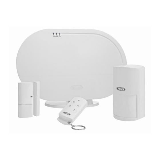
- Page 1 Smartvest User manual You can find important information and FAQs about this and other products online at: www.abus.com Version 1.2 English translation of the original German user manual. Retain for future reference.
- Page 2 ABUS Security-Center GmbH is not liable or responsible for direct or indirect damage resulting from the equipment, performance and use of this product. No guarantee is made for the contents of this...
- Page 3 Up to 32 wireless components and four IP cameras can be connected to the Smartvest alarm panel via the free app, enabling you to access the alarm panel from anywhere in the world. If an alarm is triggered, the alarm panel activates its built-in, high-volume 90 dB siren;...
- Page 4 English Power supply Only operate this device using a power source which supplies the grid voltage specified on the type plate. If you are unsure which power supply is available, contact your utility company. Disconnect the device from the power supply before carrying out maintenance or installation work. ...
- Page 5 Place or mount the device on a steady, level surface and do not place any heavy objects on the device. Make sure that there is adequate ventilation (do not place the Smartvest on a shelf, thick carpet, bed or wherever the ventilation slits may be covered. Always leave a gap of at least 10 cm on all sides).
- Page 6 Rub the surface gently with the cotton cloth until it is completely dry. The device operates with a dangerous voltage level. When conducting maintenance work (e.g. cleaning), disconnect the device from the mains. Contents Device description ........................... 8 FUAA35000 Smartvest ......................8 FUHA35000 power switch ..................... 11...
-
Page 7: Table Of Contents
FURM35000 smoke alarm/heat detector ................13 FUSG35000 siren ........................14 FUBE35000 Remote Key ...................... 15 Start-up ............................16 Installing the Smartvest App ....................16 Setting up the Smartvest ....................... 16 Pairing components ....................... 19 General settings........................21 Installation ............................23 FUAA35000 Smartvest ...................... - Page 8 English 1. Device description This chapter contains descriptions of the Smartvest and all associated components. FUAA35000 Smartvest Front System is supplied with power Power LED Green No power supply System is "disarmed" The system is "disarmed" and there is a fault Yellow (e.g.
- Page 9 English Under side To reset passwords to the default settings (123456) and network settings to DHCP: While the system is in operation, press and hold the reset button for >10 seconds using a paper clip. The power LED will go out and a continuous tone will sound.
- Page 10 Drill hole spacing: 10 cm (drilling template provided) Loudspeaker Smartvest loudspeaker with a maximum volume of 90db. System is "disarmed" The system is "disarmed" and there is a fault Yellow (e.g. battery dead or magnetic contact is "open") Background ...
- Page 11 English FUHA35000 power switch Schuko socket type F (CEE 7/4). Can be used in the following countries: Schuko socket Germany, Austria, Sweden, Netherlands Power switch is activated; power is being transmitted. Power switch is ready and activated; power is not being transmitted to the consumer.
-
Page 12: Fumk35000 Magnetic Contact
Signal LED Blue Flashing Magnetic contact is opened 1x 3V button battery (CR2032) for power supply (up to one year battery life). The Smartvest App warns you when the battery is low. Follow the instructions in the app. Battery operation Changing the battery Slide the battery compartment cover out in a downwards direction. -
Page 13: Fubw35000 Pir Motion Detector
Tampering contact for alarming in the event of unwanted removal contact 3 x AA (1.5 V) batteries for power supply (up to two years battery life) The Smartvest App warns you when the battery is low. Follow the instructions in the app. Battery ... -
Page 14: Fusg35000 Siren
Loudspeaker Siren loudspeaker with a maximum volume of 80 db or 100 db. Pair button Button for manual pairing with the Smartvest Tampering Tampering contact for alarming in the event of unwanted removal contact 4 x C (1.5 V) batteries for power supply (up to two years battery life) Changing the battery Loosen both screws on the cover. -
Page 15: Fube35000 Remote Key
Button for triggering the panic alarm (press for 3 seconds) 1x 3V button battery (CR2032) for power supply (up to two years battery life) The Smartvest App warns you when the battery is low. Follow the instructions in the app. -
Page 16: Start-Up
English 2. Start-up Before installing your Smartvest and detector, follow the steps below to start up your Smartvest and pair components with the Smartvest. Installing the Smartvest App For the Smartvest, there is an app called "Smartvest" available for download from the Google Play Store and the iOS App Store. This app can be used on smartphones and tablets, referred to as "end... - Page 17 The app then automatically searches for devices on your network. Select Select your Smartvest from the list. If you want to link the Smartvest from another network or the Smartvest is not found, enter the DID manually. All further entries must then also be made manually.
- Page 18 Name assignment, room and location information Assign a name to the Smartvest. The name "Smartvest" will be stored initially. Open the room list and select a room where the Smartvest is mounted. Tap the arrow to return to the previous window.
-
Page 19: Pairing Components
English Pairing components Open the Smartvest App and connect to the Smartvest. Note The settings for your components can be found in chapter 5.1, Components. Carry out the following steps: Open Smartvest settings To access the Smartvest settings, tap the settings symbol the bottom left-hand corner of the operation view. - Page 20 Smartvest alarm control panel using a LAN cable, you can also adjust the settings using the Smartvest app. Chapter 5 (Configuration) describes how to pair the camera. Now install the components and the Smartvest as described in the following chapter ("Installation").
-
Page 21: General Settings
Available systems Add a new Smartvest to the app or select your Smartvest to access the Smartvest's general settings. Smartvest details If the security code has been changed or entered incorrectly, you can adjust this here for the Smartvest connection. - Page 22 Disable "Automatic log in" for the app PIN to ensure the app PIN is requested each time the app is started. Use this to prevent anyone else using the end device from accessing the app. Manual Here you can access the Smartvest manual from your smartphone.
-
Page 23: Installation
English 3. Installation This chapter describes how to install the Smartvest and the associated components. Please refer to chapters 4 and 5 when operating and adjusting the settings for the Smartvest via the Smartvest App. Warning When using adhesive pads, ensure that the surface below is clean, abrasion-resistant and dry. -
Page 24: Fuha35000 Power Switch
English Wall installation Stick the Smartvest drilling template to the desired installation location. Use a spirit level to ensure the drilling template is straight. Drill holes in the specified positions and insert the screw anchors provided. Screw the screws provided into the screw anchors so that the heads protrude by around 6 mm, then mount the Smartvest. - Page 25 English Installation with adhesive pads (recommended) 1. Stick both the small adhesive pads on to the magnetic contact's large transmitter components and the longer adhesive pad on to the smaller magnet component. 2. Stick the large transmitter component to the window frame in the desired position in relation to the window and stick the smaller magnet component to the window itself.
-
Page 26: Fubw35000 Pir Motion Detector
English FUBW35000 PIR Motion Detector The motion detector is only suitable for indoor use. For further information, please refer to the safety instructions relating to installation location and operating environment. General installation instructions Install the motion detector 2–2.5 m above the ground for a range of 12 m. ... -
Page 27: Furm35000 Smoke Alarm/Heat Detector
English Drill installation using bracket 1. Press the bracket into the motion detector. 2. Hold the motion detector next to the desired installation location and adjust to the desired angle. 3. Fix the position by tightening the screw on the rear of the bracket. 4. -
Page 28: Fusg35000 Siren
English FUSG35000 siren The siren is suitable for indoor and outdoor use. For further information, please refer to the safety instructions relating to installation location and operating environment. General installation instructions Warning The tamper contact may be triggered when installing the siren. In this event, the siren is set to "LED"... -
Page 29: Fube35000 Remote Key
English FUBE35000 Remote Key The Remote Key is only suitable for indoor use. Note the information provided in the safety instructions relating to the operating environment. Installation Use the keyring to attach the Remote Key to your bunch of keys or similar. -
Page 30: Operation
4. Operation The Smartvest App is divided into two basic menus, operation and configuration. This chapter will show you how to operate the Smartvest via the Smartvest App. Please refer to chapter 5 to find out how to configure the Smartvest. -
Page 31: Navigation Bar And Footer
Footer Settings The settings symbol is located in the bottom left-hand corner of the footer. Tap this symbol to access the Smartvest settings. Temperature, humidity and weather display Temperature, humidity and weather information are displayed in the bottom right-hand corner. -
Page 32: Overview
Status display Three different symbols are used to represent the different Smartvest statuses in the status display. The current status is marked in colour, with the relevant text shown below. You can change the status by dragging to the left or right or, alternatively, by tapping the desired status. - Page 33 English Hotkeys There are two pre-configured hotkeys – panic and camera – below the status display, which you can tap and enable in the overview. These two hotkeys are also found on the FUBE35000 Remote Key and can be operated from there. Standard: All actuators are triggered (e.g.
-
Page 34: Hotkeys
English Hotkeys Application examples Hotkeys enable straightforward activation of various components with just a tap. Should you become aware of any potential intruders outside your house before they have attempted to break in, you could, for example, configure a hotkey (panic) to activate the siren, which you could then tap to scare off the intruder before they break in. -
Page 35: Rooms
English Rooms Room overview In the room overview, all rooms with at least one added component are shown. A maximum of two components are shown under the room name. Room details Tap the desired room to open the individual room overview. All components which have been added to the room are then listed. - Page 36 English...
-
Page 37: Cameras
English Cameras Camera overview Up to four cameras can be displayed in the camera overview. In the settings (see chapter 5.5, Advanced settings), you can add four cameras in the contact overview or edit the settings for the cameras already available. You can access the live view with the various camera functions by tapping the relevant camera. - Page 38 English TVAC19100 Live view Move two fingers away from each other on the screen to zoom in on the camera image. Actions Activate microphone Tap this button to listen to the camera's recorded audio. Snapshot Tap this button to save a snapshot on your end device.
-
Page 39: Contacts
English Contacts Contact overview Up to four contacts can be displayed in the contact overview. Two pre-configured contacts – emergency and police – are already stored upon initial start-up. In the settings (see chapter 5.6, Contacts), you can add two further contacts in the contact overview or edit the contacts already available. -
Page 40: Basic Event
Event overview When calling up the event list, the 100 most recent events are displayed. To view older events, use the search function. The Smartvest alarm control panel stores a maximum of 1000 entries. Note Camera events will be loaded directly from the camera into the event overview and updated. -
Page 41: Alarm View
Smartvest App is already open the Smartvest App is opened after the alarm the Smartvest App is opened by tapping the alarm's push notification. Chain of events The chain of events shows you which event triggered the... -
Page 42: Configuration
5. Configuration The Smartvest App is divided into two basic menus, operation and configuration. This chapter will show you how to configure the Smartvest via the Smartvest App. Please refer to chapter 4 to find out how to operate the Smartvest. -
Page 43: Configuration Overview
If you have designated at least one contact as a selected helper, this contact is displayed as a call option the next time there is an alarm on the Smartvest. Up to two of the four contacts can be designated as selected helpers. -
Page 44: Components
Smartvest alarm control panel using a LAN cable, you can train the camera using the Smartvest app directly, as well as configuring it and then switching to WLAN operation. To establish a direct WLAN connection, first follow the camera's instructions for setting up the camera on your home network. - Page 45 English If the pairing process was not successful, repeat the steps. Opening detector Enter a name for the component. Open the room list and select the room where the component is installed. Tap the arrow to return to the settings.
- Page 46 English Note If the pairing process was not successful, tap "Pair", loosen the smoke alarm/heat detector from the base plate, remove and replace the batteries. Siren Enter a name for the component. Open the room list and select the room where the component is installed.
- Page 47 Duration of the reaction Set the alarm duration for the alarm control panel in the event of an alarm. Room Open the room list and select a room where the Smartvest is mounted. Tap the arrow to return to the settings. Town...
- Page 48 English Opening detector Name Enter a name for the component. Room Open the room list and select the room where the opening detector is installed. Tap the arrow to return to the settings. Motion detectors Name Enter a name for the component. Room Open the room list and select the room where the motion detector is installed.
- Page 49 Remote control Name Enter a name for the component. Room Open the room list and select a room where the Smartvest is mounted. Tap the arrow to return to the settings. The "Mobile devices" room is available for the Remote Key.
- Page 50 English Camera Name Enter a name for the component. Read the camera's DID number here. Security code Entering the camera's security code Advanced settings Open the advanced settings by entering the camera's admin code (default setting: 123456). Room Open the room list and select the room where the camera is installed.
- Page 51 English Adjusting for poor light conditions If light conditions are poor in night mode, adjust the video image using the 5 levels. Level 5 brightens the image as far as possible. Image alignment Here you can rotate, mirror, or rotate and mirror the image. WiFi settings Select the required network that will be used for the camera to access the Internet and enter the correct WLAN password.
-
Page 52: Hotkeys
English If this function is activated, the newest recordings overwrite the oldest ones once the SD card is full. Device information Here you can read the firmware version, as well as the total storage and available storage space. Hotkeys Hotkeys Tap the configured hotkeys (panic or camera) or one of the nine configurable hotkeys in order to configure these. -
Page 53: Scenarios
English Scenarios Application examples Scenarios allow you to automate certain actions in your home; for example, you can use a motion detector when a room is entered or a magnetic contact when a door is opened to switch on a light source connected to a power switch. You could also use a motion detector or magnetic contact to start a camera recording, which allows you to always have an overview of who has entered your house and when. -
Page 54: Schedules
English Schedules Application examples Schedules allow you to automate certain actions in your home as well as providing presence simulation. You can store schedules for each power switch to activate light sources that are connected to a power switch and simulate a presence when you are away, while on holiday for example. You could also connect your Christmas lights to a power switch and activate these at night-time only using a schedule. -
Page 55: Advanced Settings
English Advanced settings Network settings The Smartvest is set to DHCP by default. This means that the Smartvest is automatically assigned an IP address, subnet mask, gateway and DNS server by your router. Should you wish to enter these manually, switch DHCP to "Off"... - Page 56 "Active" status. Exit delay Activate the exit delay so you have enough time to leave the house after arming the Smartvest. The exit delay applies for both "Active" and "Part set". Note In "Active" status, all actuators and sensors are...
- Page 57 "Part set" status. Exit delay Activate the exit delay so you have enough time to leave the house after arming the Smartvest. The exit delay applies for both "Active" and "Part set". Note In "Part set" status, all actuators and sensors are activated as standard, with the exception of motion detectors.
- Page 58 Smartvest. Adopt time Tap "Adopt time" to transfer the current time zone and time from your smartphone to the Smartvest. About Tap "About" to view up-to-date information on the Smartvest DID, the current firmware version and the current app version.
- Page 59 English Special mode Maintenance mode Set the system to maintenance mode to avoid triggering the tamper alarm and a supervision fault when changing the battery. Attention Do not forget to deactivate maintenance mode again for normal operation. Test mode After activating test mode, a view appears showing all new events including motion detection.
-
Page 60: Technical Data
English 6. Technical data FUAA35000 – Smartvest Model number Battery 6 x AA (2 x 3) (1.5 V) as a backup power supply Battery life Ø 5 Operating temperature °C 0–40 Frequency 868,3 Weight Hygrometer integrated Dimensions 279.6 x 89.3 x 193.8 Max. - Page 61 English FUMK35000 – magnetic contact Model number Battery 1 x CR2032 (3V) Battery life Ø 1 year Operating temperature °C 0–40 Frequency 868,3 Weight Dimensions 40 x 71 x 14 Max. humidity Installation Door or window installation Range approx. 30 depending on the local conditions Tamper monitoring Signal check Yes, time interval 3 h...
- Page 62 English FURM35000 – smoke alarm/heat detector Model number Alarm muting Battery 2 x AA (1.5 V) Battery life Ø 1 year Operating temperature °C 0–45 Detection range m² Frequency 868,3 Weight Dimensions 32 x 120 Max. humidity Installation Ceiling installation Range approx.
- Page 63 English Battery 1 x CR2032 (3V) Battery life Ø 2 years Operating temperature °C 0–40 Frequency 868,3 Weight Dimensions 30 x 60 x 14 Max. humidity Installation Door or window installation Range approx. 30 depending on the local conditions Tamper monitoring Signal check Yes, time interval 3 h...
Need help?
Do you have a question about the Smartvest and is the answer not in the manual?
Questions and answers