
Related Manuals for Abus Secvest IP


Summary of Contents for Abus Secvest IP
- Page 1 Secvest IP wireless alarm centre Installation and operating instructions (UK) FUAA10011...
-
Page 2: Table Of Contents
Installation Installation of the backup battery (backup power supply) Display and setting elements Labelling the Secvest IP Putting into operation Enclosed software Configuration of the web server ... -
Page 3: Preface
2. Preface Dear customer, Many thanks for your purchase of this Secvest IP wireless alarm centre. This product is built according to state-of-the-art technology. It complies with current domestic and European regulations. Conformity has been proven, and all related certifications are available from the manufacturer on request (www.abus-sc.com). -
Page 4: Meaning Of The Symbols
4 Meaning of the symbols 4. Meaning of the symbols Disposal as per directive WEEE 2002/96 EC At the end of its useful life, dispose of the product according to the applicable legal requirements. Within the EU, the product and its accessories must be collected and disposed of separately. -
Page 5: Power Supply
5 Important safety information Warning All guarantee claims become invalid for damage caused by non- compliance with these operating instructions. We cannot be held liable for resulting damages. Warning We cannot be held liable in the event of material or personal damage caused by improper operation or non-compliance with the safety information. - Page 6 5 Important safety information Cables • Always hold cables by the connector, and do not pull the cable itself. • Never touch the mains cable with wet hands, as this can lead to a short circuit or electric shock. • Never position the device, furniture or other heavy items on the cable.
- Page 7 5 Important safety information • The device must not be exposed to strong variations in temperature, as this can lead to condensation and electrical short circuits. • The device must not be exposed to excessive jolts or vibrations. Care and maintenance Maintenance is necessary if the device has been damaged.
-
Page 8: Children And The Device
1 x backup battery 1 x 1 metre network cable 1 x Quick guide 1 x CD-ROM (installation and operating instructions, Secvest IP Finder, labelling templates) 1 x installation material (4 x wall plugs, 4 x screws) 1 x battery cable... -
Page 9: Compatibility With Abus Products
7 Compatibility with ABUS products 7. Compatibility with ABUS products Compatible CASA10010 IP alarm module FU59xx Secvest Key 2WAY wireless cylinder FU8100 Secvest 2WAY wireless remote control (integrated panic function not usable) FU8130 Secvest 2WAY wireless additional lock (7010E) FU8140... -
Page 10: Installation
8 Installation 8. Installation Key: Wall tamper switch Housing screw Fixing holes on base plate Cable opening Tension relief (bar for fastening cable to cable clip) Installation procedure: 1. Loosen the housing screw on the bottom narrow side and open the housing. 2. -
Page 11: Installation Of The Backup Battery (Backup Power Supply)
9 Installation of the backup battery (backup power supply) 6. Fasten the 13.8 V cable and LAN cable to the appropriate tension relief using the supplied cable clips. 7. Fix the housing to the wall. 8. Make sure the spring of the wall tamper switch (A) is positioned correctly. 9. -
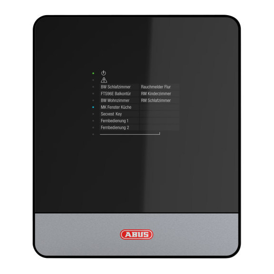
Page 12: Display And Setting Elements
10 Display and setting elements 10. Display and setting elements 10.1 Display LEDs The display consists of 10 LEDs Green LED (“Power” LED) for monitoring the power supply • Permanently lit: Power supply is OK • Flashing with 1 Hz: Mains power supply failure; only indicated if a backup battery is in use. - Page 13 10 Display and setting elements 10.3 Acoustic signal The alarm centre can also signal the various states and error messages acoustically: 1 x beep Centre was deactivated 2 x beep Centre was activated 8 x beep System error (tampering, jamming, supervision), zone is open while activating the system 10.4 Setting elements on the wireless PCB...
- Page 14 (The installer mode is deactivated in the factory default setting.) This mode is useful for changing the battery. You can open the housing without the siren emitting any sound. The Secvest IP must also be in the “training mode” to suppress e-mail notification. („System...
- Page 15 10 Display and setting elements 10.5 Setting elements and connections on the IP board System reset button Restart button Relay outputs Burglary Fire Panic Transistor outputs DSL monitoring 10. 0 V 11. + terminal for power supply unit 12. – terminal for power supply unit 13.
- Page 16 In an activated state, the output is at 12V. For the numbering, refer to the chapter on “Setting elements and connections on the IP board”. Power supply for the GSM/PSTN dialler is not possible using the Secvest IP power supply unit included.
-
Page 17: Labelling The Secvest Ip
11 Labelling the Secvest IP 11. Labelling the Secvest IP We recommend using the editable PDF on the supplied CD for labelling your Secvest IP, or downloading the PDF for the corresponding product from our website. Labelling the device is very simple. Enter your individual component settings in the PDF and print it out. -
Page 18: Enclosed Software
13 Enclosed software 13. Enclosed software The Secvest IP Finder is used to identify the Secvest IP in the network. It allows the corresponding IP address of the components located in the network to be determined. Install and start the IP Finder. You will find it on the accompanying software CD. -
Page 19: Configuration Of The Web Server
Secvest IP using the integrated web server in the alarm centre. 14.1 Login In order to change the settings on the Secvest IP using the web server, you must first log in to the web server as follows: Select your language Enter your user name (default: “admin”) - Page 20 14 Configuration of the web server 14.2 Overview The “Overview” screen shows the current status of the Secvest-IP alarm centre, and is divided into three areas: 1. Inputs: In the Inputs area, you will see an overview of the state of the three wireless zones (1) and three virtual IP zones (2).
- Page 21 14 Configuration of the web server Creating/displaying/downloading live snapshots from PIR network cameras Under “Inputs”, live snapshots from trained PIR cameras can also be viewed and downloaded if required. This feature allows the ACTUAL status of a zone monitored by a PIR network camera to be checked. By clicking on the name of the zone for the required PIR network camera, 9 live snapshots are created at a delay of approx.
- Page 22 14 Configuration of the web server The 9 snapshots can be downloaded by clicking on “Download”, and saved. The snapshots can also be downloaded as TAR archive. Ensure that a TAR compatible data compression program is used to unpack the archive (such as WinRAR or 7 Zip).
- Page 23 14 Configuration of the web server 2. Outputs: The Outputs area lets you switch the two wireless switching outputs (1 and 2) and the relay output (3). The current status can also be determined at this time. If the LED on the button lights up and the lettering has a blue background, this indicates that the output is currently switched on (see (1)).
- Page 24 14 Configuration of the web server 3. Alarms: The Alarms area is used to indicate whether any alarms are present (and if so, which ones). Possible Alarms: Burglary Fire Panic Technical Fault − Jamming − Supervision − Tampering System faults can only be cleared −...
- Page 25 14 Configuration of the web server 4. Web server acoustic signalling If the alarm centre is activated/deactivated, or if an alarm is triggered, the web server sends acoustic feedback to your web browser. (If an alarm is triggered, an additional siren alarm signal is emitted until the alarm is reset/the centre is deactivated) The acoustic signaling in the web browser is only possible on HTML5-compatible browsers: Internet Explorer 9 (or above), Firefox...
- Page 26 14 Configuration of the web server 14.3.1 RF-Inputs Name: Name of the zone/specification whose name is used in the zone display in the “Overview” menu. Bypass (on/off): The selected zone is hidden (i.e. zones can be deactivated). This function can be used to bypass specific zones and their detectors, when necessary (e.g.
- Page 27 14 Configuration of the web server Event (zone attribute): Zones can have very different attributes. The assignment is made according to the type of trained detectors on the zone. The detector sends an alarm notification to the alarm centre, which then triggers a reaction depending on the set event properties and alarms.
- Page 28 14 Configuration of the web server 14.3.1.1 Virtual Inputs (vChannel) In the virtual inputs area, the settings can be made for connecting IP components. (e.g. PIR IP camera, IP alarm module). As in the wireless inputs area, the virtual inputs can be concealed, the internal activation configured, as well as the event connected to the alarm.
- Page 29 14 Configuration of the web server Sensor: Internal setting: the network camera sends a warning via the internal PIR sensor and has a warning function only. External Setting: the network camera is in the recording mode and reacts in the alarm centre in the event of an alarm. Port: enter the network port of the connected component.
- Page 30 14 Configuration of the web server Example: Radio Output 1, which controls a wireless socket with is connected to a light, this will be switched on in case of an alarm. By ticking the boxes under “Event(s)”, the user has the option of specifying which events switch the outputs (e.g.
- Page 31 14 Configuration of the web server • Scheduler: The option scheduler enables you to assign a scheduler to this specific output. The assigned scheduler will be active at the same time with enabled events. In case of simultaneous triggering based on scheduler trigger and event trigger the latest trigger event is valid.
- Page 32 14 Configuration of the web server Scheduler 1-2 configuration: Each scheduler can store up to 5 individual triggering events. The column “Set” defines time to arm the panel, the column „Unset“defines time to disarm the panel. You can configure an individual name within input box for „Name“. This will help later on to assign schedulers more easily.
- Page 33 14 Configuration of the web server Application examples: Set: 19:00 Unset: 07:30 Cycle: Mon, Tue, Wed, Thu, Fri Effect: The alarm panel will disarmed at 07:30 a.m. and armed at 7.00 p.m in the evening. The scheduler will be valid within Monday to Friday.
- Page 34 In user account configuration area System User Account you can assign scheduler 1 or scheduler 2 for automated arm- and disarming of Secvest IP alarm panel. The individual scheduler name will shown in dropdown list. Please press Apply in order to save the configuration data and to activate the scheduler.
- Page 35 14 Configuration of the web server The following configuration can be applied to each trigger time: Hours Minutes Description Trigger at 08:15 a.m. Start triggering at 08:00 a.m. each hour until end of the day. Triggers on15th minute every hour. Please choose at least one day by clicking on checkbox to activate the scheduler.
- Page 36 14 Configuration of the web server Assing scheduler 3-6: Within output configuration area you can assign the schedulers by clicking on “scheduler” dropdown list. You can assign the same scheduler to each output of your Secvest IP alarm panel at the same time.
- Page 37 14 Configuration of the web server 14.6 Notification In this menu, you specify the settings and rules for e-mail notifications. The Notification menu is divided into six areas, which can then be used to adjust the notification function to your own requirements: Email account: Server setting for sending emails Messages:...
- Page 38 14 Configuration of the web server E-Mail Account The “E-Mail Account” area is used to enter the data of the account from which notifications are sent in the event of an alarm. Aside from the name and e-mail address, the contact information of the outgoing mail server, user name and password of the e-mail account must be entered.
- Page 39 14 Configuration of the web server Messages Text messages for the respective event type can be stored under the “Messages” menu item. These messages are then sent automatically to the corresponding e-mail addresses in the event of an alarm. To add a message, click “Add Message”.
- Page 40 An SIP or PSTN (landline) number can also be stored for each recipient who can be called in the event of an alarm. To obtain an SIP number, you need to register provider (tested approved ABUS: http://www.sipgate.de http://www.localphone.com) receive your own/personal SIP number from there. Depending on the application, this needs...
- Page 41 14 Configuration of the web server Option: SIP to SIP telephony (free of charge) Format: SIP number @ provider.URL Example: 7897184 @ localphone.com SIP to SIP telephony is free of charge. The provider of the “called” subscriber needs to be entered here as the provider (=recipient – provider).
- Page 42 14 Configuration of the web server Option: SIP to PSTN telephony (subject to a charge) Format: international dialling code+local code+telephone number@provider.URL Example: +49 (0)8207 959900 @ sipgate.de For SIP to PSTN telephony, the provider must be entered where the account centre registered (=sender –...
- Page 43 14 Configuration of the web server 4. Email Rules Under “Email rules”, rules are defined by which a message and one or more recipients are clearly assigned to each event (alarm). For setting up the email notification, click an event for which a rule should be created (e.g.
- Page 44 14 Configuration of the web server One of the previously saved messages can then be selected and assigned to the “Burglary” event in the window which opens (“Select Message”). Confirm your selection by clicking “OK”. Recipients must now be assigned to the defined message for the “Burglary”...
- Page 45 The standard setting for the subject line is “Centre name – event name” (Secvest IP burglary). You can change the text by entering the text field. By clicking on the waste paper bin symbol, the...
- Page 46 Configuration of SIP call for alarm (SIP rules) To activate SIP telephony, move the regulator to “On”. You obtain the domain, user ID and password when your provider creates your SIP account. Providers tested by ABUS: http://www.localphone.com http://www.sipgate.de Depending on provider, nomenclature of user ID and password can be different: Sigate.de...
- Page 47 14 Configuration of the web server The name of your SIP account can be assigned individually. See also [page 45] Network „Troubleshooting SIP-dialing“...
- Page 48 14 Configuration of the web server 6. SIP Rules As under “Email rules”, “SIP rules” can also have links set up from alarm events to the recipients who should be called or contacted via SIP telephony in the event of an alarm. For setting up the SIP notification, click an event for which a rule should be created (e.g.
- Page 49 14 Configuration of the web server One of the previously saved recipients can then be selected and assigned to the “Burglary” event in the window which opens (“Select Recipient”). Confirm your selection by clicking “OK”. Next, the number of redials per recipient can be defined which are made when there is no response to a call.
- Page 50 14 Configuration of the web server Example – recipient A responds to the second round and deactivates the alarm: Recipient A (1) Recipient B (1) Recipient C (1) Recipient A (2) All the recipients are called until the alarm centre has been deactivated. Deactivating the alarm centre terminates the calling process.
- Page 51 14 Configuration of the web server 14.8 GSM Settings can be made here for using an optional GSM dialler (AZ6302) to set up a redundant communication path. To use a GSM dialler, switch GSM to “On”. The transistor outputs are now also controlled. To receive notifications exclusively via GSM, tick the “GSM Only”...
- Page 52 14 Configuration of the web server 14.9 System This menu item is used to configure the network settings, set the date and time, manage users, change the language and perform maintenance on the alarm centre itself. Settings for push notification and SD card can also be made.
- Page 53 14 Configuration of the web server 1. Network The “Mode” selection box is used to specify whether the IP address is taken automatically from the DHCP server or is assigned manually by the user via static IP. Select the appropriate setting according to your network properties.
- Page 54 14 Configuration of the web server Troubleshooting SIP-dialing Set Network mode of your alarm panel on “Static IP” and configure DNS server IP address on Google DNS server IP “8.8.8.8” (see above), if there occurs an error or SIP call is not transmitted in case of an alarm.
- Page 55 14 Configuration of the web server 2. Date & Time Set the time and date here. Selection options available: • NTP mode Time and date are obtained from an NTP server via internet. Several NTP servers can be selected here. •...
- Page 56 14 Configuration of the web server 3. User Account Two user levels can be implemented here. All setting options on the alarm centre are available on the first user level. The second user level only has the option of activating/deactivating the alarm centre or resetting the alarm and viewing the log book.
- Page 57 14 Configuration of the web server 4. Language The corresponding system language is set here. When you change the system language, the audio signalling is also automatically adjusted to the new language.
- Page 58 To start the update, click “Install”. The update process can take several minutes – never terminate the connection between your computer and the Secvest IP during this time. The system is restarted after the update is completed. Factory Settings The IP module default parameters are restored, which means that all the settings made with the web server will be lost.
- Page 59 14 Configuration of the web server Learn Mode The system can be set to “Learn Mode”, to deactivate the alarm reaction of the alarm panel. This means that detectors can be triggered and tested in this mode, but an alarm reaction cannot be triggered. This is particularly suitable for training wireless components or for maintenance.
- Page 60 14 Configuration of the web server 6. Push Notification The end devices that have been registered and set up for push notification in the alarm panel are displayed here. Click “Push Notification” to display the detailed view of the registered end devices on the control panel.
- Page 61 2.0 or higher of the Secvest IP app and control panel firmware version 2.0.5 or higher. To do this, the Secvest IP app reads the internal device name (such as ABUS iPhone) and transmits it directly to the control panel. If the device name has changed, you can update the name displayed on the control panel by repeating the “pairing”...
- Page 62 Setting up the push pairing process between the app and control panel Adding a new control panel: Load Secvest IP 2.0 or higher from the iTunes App Store onto your end device. When the app first starts, confirm the activation of receipt of “push notifications”...
- Page 63 The control panel has already been added to the app: (update from 1.5.2 to 2.0 or higher) Load Secvest IP 2.0 or higher from the iTunes App Store onto your end device. When the app first starts, confirm the activation of receipt of “push notifications”...
- Page 64 14 Configuration of the web server 7. SD Card Under “SD card”, you can make specific settings for SD cards: Memory: Shows the occupied memory on the SD card in relation to the complete capacity of the SD card. The standard capacity of the installed SD card is 2 GB –...
-
Page 65: Event Log
14 Configuration of the web server 14.10 Event Log This function enables the user to read the event log. This log contains the events together with the date and time and event type. The sort sequence can be changed from descending to ascending order using the arrow at the top left. - Page 66 After the configuration is set or operation is finished, click on the “Logout” button at the top right of the screen to log out of the Secvest IP web server. This prevents unauthorized persons using this computer from making changes to the...
-
Page 67: Teaching The Wireless Components
15 Teaching the wireless components 15. Teaching the wireless components Switching on: Connect the power supply. The alarm centre beeps twice and the top LED (green) lights up. Ensure that the tamper switches on the alarm centre are open. The “Trouble” LED flashes red with 1 Hz if the cover is open. To deactivate the wall temper switch, read the instructions below. - Page 68 Secvest IP easier. Please be also aware, that it is only possible to teach operating units, like the remote control or the Secvest Key, in channel 1 to 3.
- Page 69 15 Teaching the wireless components When you are finished, press ESC/DEL once. Pressing any other buttons has no effect on the alarm centre at this point. The bottom LED lights up again permanently. The main menu is accessed again. 15.2 Menu 2 – Deleting the components Press SELECT until the second LED from the bottom lights up.
- Page 70 15 Teaching the wireless components Note: The following table gives an overview of which components must have the channels set to “Impulse” and “Permanent”: Permanent Impulse FU59xx, FU8100, FU8130, FU8140, FU8300, FU8305, FU8310, FU8150, FU832x, FU8330, FU8370, FU8340, FU8350, FU8360, FU841x, FU842x, FU8430 FU8380, FU8390 These settings do not affect the channel of the external siren if used.
- Page 71 15 Teaching the wireless components 15.5 Menu 5 – Controlling the wireless indoor siren, wireless info module and wireless socket 15.5.1 Wireless indoor siren and wireless info module: If you want to use a wireless info module or wireless indoor siren, you must first change the setting to “Activated”...
- Page 72 15 Teaching the wireless components Socket training mode: Connect the socket to the power. Press the button on the socket for about 7 seconds until the wireless socket beeps. Keep pressing again briefly until the LED lights up yellow. Press the button again for about 4 seconds. The device beeps and the yellow LED flashes.
- Page 73 15 Teaching the wireless components Once you have switched the wireless socket to the training mode and made the required configurations on the web server, switch to the output in which you want to teach the socket or sockets via the web server. To do this, press the wireless output button on the overview screen.
- Page 74 15 Teaching the wireless components 15.6 Menu 6 – Not in use Option: Switching the display (supervision monitoring displayed on LEDs: yes/no) 15.7 Menu 7 – External siren behaviour In this menu, the type of signal from the external siren can be defined. Press SELECT until the seventh LED from the bottom lights up.
-
Page 75: Alarm Types And Notification
16 Alarm types and notification 16. Alarm types and notification Alarm Notification Explanation User-defined e-mail/optional dialler control/ Burglary event log/alarm display via web interface/ Global e-mail/optional dialler control Delayed (burglary)/event log/alarm display via web interface/APP (intrusion) User-defined e-mail/optional dialler control/ Panic event log/alarm display via web interface/ User-defined e-mail/optional dialler control/... -
Page 76: Resetting An Alarm
(3) All alarms are reset. After an alarm is issued, we recommend that you check the status of the control panel on the web server or in the Secvest IP app. -
Page 77: Maximum System Extension
18 Maximum system extension 18. Maximum system extension... -
Page 78: Firmware Display Of Wireless Pcb
“System Maintenance Firmware version“ 20. Information on additional ABUS products You can deal with any problems concerning the wireless range by using the repeater function of the Secvest 2WAY wireless universal module (FU8210). Read the user manual for the universal module. -
Page 79: Technical Data
22. Technical data Dimensions (W x H x D) 193 x 233 x 45 mm Communication / alarming Email, VoIP (landline, mobile, VoIP client) and push notification Number of operating elements Number of users Number of remote controls Number of wireless zones Number of virtual IP zones Display Status LEDs... -
Page 80: Customer Service And Support
23. Customer service and support End consumer: Please consult your dealer or installer if you have any questions. Dealers/installers: Consult our website for product support information: www.abus-sc.com ABUS Security-Center GmbH & Co. KG Linker Kreuthweg 5 86444 Affing GERMANY www.abus-sc.com info@abus-sc.com... -
Page 81: Explanation Of Terms
To receive a push notification, you need an internet connection (WLAN, UMTS,...). LAN: Local Area Network Direct connection of the Secvest IP alarm centre to a PC Cross-over cable (certain lines are swapped). Connection of the Secvest IP alarm centre through a switch Patch cable required (all wires looped 1:1).
Need help?
Do you have a question about the Secvest IP and is the answer not in the manual?
Questions and answers