Abus SECVEST Installer Manual
Hide thumbs
Also See for SECVEST:
- Installer manual (400 pages) ,
- Installation instructions and user manual (181 pages) ,
- User manual (82 pages)
Table of Contents
Advertisement
Quick Links
Download this manual
See also:
User Manual
Advertisement
Table of Contents

Related Manuals for Abus SECVEST


Summary of Contents for Abus SECVEST
- Page 1 ABUS | Security-Center abus.com SECVEST Installer manual V2.01.08...
-
Page 2: Declaration Of Conformity
<2.00.00. Declaration of conformity ABUS Security-Center hereby declares that the radio equipment type FUAA50xxx is in compliance with RED Directive 2014/53/EU. The full EU Declaration of Conformity text can be found at: www.abus.com... -
Page 3: Table Of Contents
Contents ................................... 3 Quickstart guide ................................6 Target audience ................................6 Installing Secvest ................................6 Configuring Secvest ................................. 6 Secvest function test ................................ 6 Safety information ................................7 Explanation of symbols ..............................7 Intended use ..................................7 General .................................... 7 Power supply ................................... - Page 4 Contents Add wireless control panel ............................51 External Sirens ................................. 53 Info module/indoor siren ............................55 WUM (Wireless Universal Module) ........................... 56 Door locks ................................. 58 RF repeater ................................59 Outputs................................... 62 Radio Outputs ................................62 Wired Outputs ................................63 Partitions ..................................
- Page 5 Contents Nursing emergency call ............................... 155 Test ....................................156 Log ....................................172 Virtual keypad ................................173 Appendix ..................................174 Technical data ................................174 Compatible equipment ..............................184 Default values/factory defaults ............................ 189 Installer Mode ................................. 189 User menu ................................202 Repairs and maintenance ............................
-
Page 6: Quickstart Guide
Follow the instructions in user training in the appendix. Installing Secvest The installation of the Secvest wireless alarm system is described in chapter Mounting/Installation from page 21. Additional information can be found in the document supplied in the scope of delivery, "Quick Guide FUAA50000". -
Page 7: Safety Information
Safety information Safety information Explanation of symbols General The following symbols are used in this manual and on the Before using this device for the first time, please read the device: following instructions carefully and observe all warning information, even if you are familiar with the use of Symbol Signal Meaning... -
Page 8: Power Supply
Safety information Basics: Note User names and codes for logging into security Connection to the public electrical grid is subject systems should be known only by the legal owners to your country’s specific regulations. and never given out to unauthorised parties. Please seek information on these regulations ... -
Page 9: Wireless Operation
Note Position the alarm panel so that signal tones Note can be heard even outside of the area being No wireless licence is required for Secvest and its monitored. components. The alarm panel should be positioned within The send/receive properties could be affected by a monitored zone so that an unauthorised person other signals (e.g. -
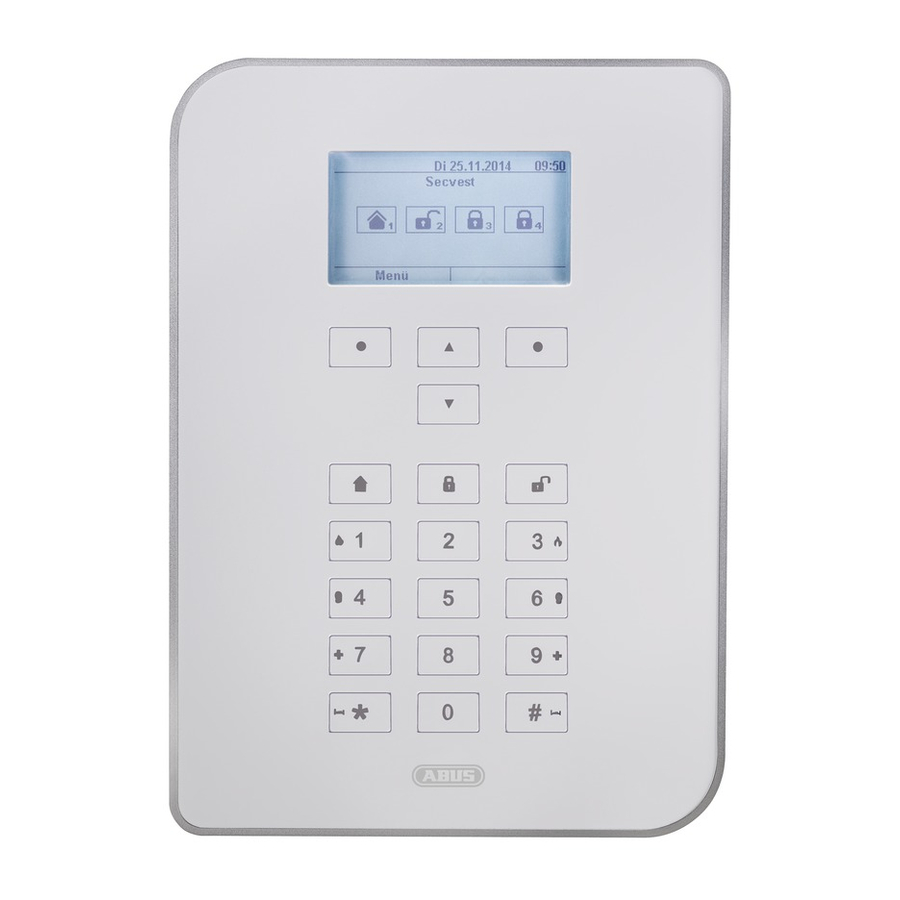
Page 10: Device Overview
Navigation buttons Proximity reader Used to navigate up/down Reader for the proximity keyfob. Hold the keyfob in front of the ABUS logo. Internal arm button Perimeter monitoring is activated (device armed internally). -
Page 11: International Key Assignment
Device overview International key assignment... -
Page 12: Device Rear (Mounting Plate)
Device overview Device rear (mounting plate) No. Name/function No. Name/function Mounting opening for screws Connection for LAN cable Housing tamper switch Connection for mains voltage 110 V/230 V AC 50/60 Hz Code reset PINs , see note below Micro SD card holder Connection for optional GSM module Fuse holder for mains fuse (FUMO50000) - Page 13 Device overview 1. If possible, go to installation mode. Note: If you cannot go into installation mode, the alarm panel will sound a tampering alarm when you open the housing. 2. Open the housing. Disconnect the entire power supply (mains voltage and batteries). Note: This procedure will not work if the tamper switch on the cover is closed.
-
Page 14: Introduction
Introduction Introduction Terms and definitions Access level 1-4 Receiving centre; in an alarm receiving centre, Access level 1-4, also known as level 1-4, messages collected in connected subscriber zones, In accordance with e.g. from danger alarm systems or building technical EN50131-1 Section 8.3.1 equipment, are transmitted, received, documented and EN50131-3 Section 8.3.1... - Page 15 Introduction The DNS works like a telephone directory enquiries Coding of wireless signals centre. The user knows the domain (the "friendly" Ensures secure transmission of signals without computer name on the IP network), such as manipulation or tampering between the alarm panel and "example.org".
- Page 16 Introduction HTTPS HyperText Transfer Protocol Secure, a communications Internet Protocol, a network protocol widely used in protocol on the web, used to transfer data securely. computer networks. HTTPS is used online to establish confidentiality and Jamming integrity in communications between web server and web Interference that makes normal reception of wireless browsers (clients).
- Page 17 Introduction Opening detector Remote access/remote configuration A detector that identifies when a window, door, shutter, Servicing/configuration of the alarm panel from outside garage door, etc. is opened. of the monitored premises (e.g. via the internet). Outdoor siren Rolling code (RC) Sounder for outdoor use, usually designed as a Rolling code is a technology which provides optimum combination sounder (siren + strobe).
- Page 18 Introduction Switzerland: the frequency use plan is set out in the SMSC Swiss National Frequency Assignment Plan (NaFZ) and Short Message Service Centre published by the Federal Office of Communications F-SMSC = SMSC for landlines Seismic sensor SMTP, SMTP server See shock detector.
- Page 19 Introduction Status Alarm panel status: armed, internally armed or disarmed. Verband der Schadensversicherer (German Association of Insurers against Loss or Damage); defines guidelines Supervision for different safety and security levels. The alarm panel monitors whether detectors are present VDS-A for the non-commercial sector and active.
- Page 20 Introduction Wireless Remote Control For convenient arming/disarming of the alarm panel, status query, emergency alarm, etc. regardless of the user’s location. Wireless window lock/wireless door lock Combination of mechanical lock and electronic detector. Pry-attempt monitoring is also possible. i.e. even attempts to break in are detected.
-
Page 21: Mounting/Installation
Mounting/Installation Mounting/Installation Connection overview, terminal block No. Name/function No. Name/function NO2, C2, NC2 – relay output 2: DC IN 13.8 V +: Connection for voltage supply 13.8 V potential-free relay contact, 30 V DC, 24 V AC rms, 500 mA OP3/4 –... -
Page 22: Fixing The Mounting Plate To The Wall
Mounting/Installation Fixing the mounting plate to the wall Positioning the wireless alarm system Fixing the mounting plate (alarm panel) Danger Note The alarm panel is supplied power via an integrated power supply unit. The alarm panel should be positioned in a safe place out of sight of possible intruders and easily The power supply unitis connected to the building’s 230 V AC grid via a separately secured... -
Page 23: Connecting The Components
Either plug the external power supply unit into the socket false alarms. or turn on the circuit that provides the Secvest with 230V. The costs incurred by potential dispatches of Tip: rescue services, such as the fire service or police, must be borne by the operator of the system. -
Page 24: Commissioning
IP address indicated by the alarm panel. the current date Alternatively you can also use the ABUS IP Installer to display the alarm panel and automatically access the current time it. You can download the IP Installer from ... -
Page 25: For A System That Is Already Installed
S/W >=2.00.00 When you make these changes in the installer mode, they will be saved directly in the Secvest’s permanent storage following confirmation. They will be preserved, even in the event of power failure before you exit installer mode. - Page 26 Commissioning Automatic log out function: Based on the Secvest’s automatic log out function, this is now also possible on the web interface and Secvest app. Installer or level 4 user is logged into the web interface. The automatic log out occurs after 1 hour of inactivity.
-
Page 27: Configuration
Configuration Configuration Notes Please consult the user manual for details on activating and deactivating the system, and on the behaviour of the alarm control panel and the display (user interface). The wireless alarm panel is configured in installer mode. There are two ways to configure the wireless alarm panel: ... -
Page 28: Menu Control Elements
Configuration Menu control elements No. Name/function No. Name/function Info bar Main menu list Active main menu – here, "Info" with additional The main menus are displayed submenus Button for online help Submenu list Click this button to open the current ... -
Page 29: Login Screen
Configuration Login screen No. Name/function No. Name/function Input field for the user name Login button Enter the Installer names. The entry is case-sensitive. Input field for the password Enter the Installer password. Note for S/W <1.01.00 The default installer password is 9999(99). -
Page 30: Main Menu
Configuration Main menu No. Name/function Page No. Name/function Page INFO Outputs General information about: Overview/configuration of the outputs: the alarm panel wired output communications wireless (radio) output customisation the software and hardware version Status Partitions Information about the status of the Overview/configuration of the partitions... - Page 31 Contacts Nursing emergency call Virtual keypad Overview/configuration of the nursing Virtual Secvest keypad. emergency call The virtual keypad can be used to operate the system in exactly the same way as the keypad on the front of the Secvest device.
-
Page 32: Info
Configuration INFO Alarm panel S/W <2.00.00 Name/function Explanation Version Version number of the software currently installed on the alarm system Serial Number Serial number of the alarm system Part No Article number of the alarm system Language Version number for the configured language... - Page 33 Configuration S/W >=2.01.08 Name/function Explanation Version, language Version number of the software currently installed on the alarm system Version number for the configured language Serial Number Serial number of the alarm system Part No.: Article number of the alarm system RF Device Exclusivity only new wireless components that have been on the market since 2015 can be added, e.g.
-
Page 34: Communication
Output voltage to the power supply output terminal Communication PSTN Name/function Explanation PSTN Link Status PSTN link status query. Secvest checks the connected telephone line. The message "OK" appears. If it is not connected, not enabled or is disrupted, the error message "Fault" appears. - Page 35 255.255.255.0. Gateway IP address If the Secvest is located on a network the IP address of the gateway is shown here. An example of a gateway in a private network is the router, e.g. the Fritz!Box. DNS primary IP address...
- Page 36 Configuration Customisation Name/function Explanation Please offer… -> ID of the wireless alarm system (required for the licence key) Please enter code Input field for the licence key for customisation of the alarm system (language settings, for example) Note The possibility of individual customisation via this menu is currently only intended for special applications upon consultation with sales or support.
-
Page 37: Status
Configuration Status No. Name/function No. Name/function Partition selection Status display Selection fields/tabs for individual partitions: The status display contains information including: An alarm that is confirmed by the user but faults in the individual partitions Faults across partitions not reset is displayed in the corresponding partition as a warning symbol. -
Page 38: Components
Configuration Components Teach-in via web interface From S/W 2.00.00 onwards, teach-in is possible via the web interface. To do this, simply click on an as yet unassigned zone, siren etc. The system will guide you through the teach-in process. Once teach-in is complete in the web interface, you must define the zone type. - Page 39 Configuration Name/function Explanation Name Unique name of the zone Sub-area Partition of the individual zone Type Type of the individual wireless zone Attributes Overview of the attributes for the individual wireless zone...
-
Page 40: Detectors
Configuration Detectors IP zones Name/function Explanation Number The number comprises the zone name and the component type (IP). Name Unique name of the zone Sub-area Partition of the individual zone Type Type of the individual IP zone Attributes Overview of the attribute and status of the individual IP zone Note To integrate a network camera into a free IP zone, it must first be integrated and configured in the alarm panel network (see installation instructions TVIP41550 or IPCx Range). - Page 41 Recordings (videos/pictures) from the IPCxyyyyyy cameras can only be called up via the camera’s web server or via the ABUS iDVR App (not via the alarm control panel log book) URL/link to the camera in the log book for all events for which there are recordings available Add/delete Select the desired IP zone in the menu "Devices"...
- Page 42 Configuration Partitions to be monitored when trigger events occur. IP address IP address of the camera in the internal network HTTP port of the camera in the internal network (default setting: “80”) HTTP Port Internal RTSP port of the camera in the internal network (default setting: “554”) RTSP Port Internal HTTP Port External External HTTP port for which port forwarding in the router is configured...
- Page 43 This zone is used with lock switch contacts. Note This zone type was used in the Secvest 2WAY as a zone attribute rather than a zone type. Exit Norm Alm A zone configured as "Exit Norm Alm" behaves similarly to a "Normal Alarm" zone. A zone of this type, however, starts an alarm even when the detector is triggered during the exit time.
- Page 44 Configuration Type Explanation Final Door When the alarm panel is armed, this zone triggers an alarm once the set delay time (entry delay) has expired. Use this zone type for the magnetic contact on the entrance door, for example. When exiting the premises, closing this zone can also be used to end the exit delay. This detector can be used as a "Normal Alarm"...
- Page 45 Configuration Type Explanation HUD Fault This zone is used to monitor the fault output of wired hold up signalling devices. If a hold up device with this zone type is triggered, "HUD Fault" appears on the display. This message also appears on the display if the user tries to arm the wireless alarm panel while an alarm is active.
- Page 46 Setting options for the partitions can be found in section A "W" appears in the attribute line on the "Configuring Secvest via web server -> Partitions" in this alarm panel display. manual. Soak Test...
- Page 47 Configuration Note The Soak Test function should only be set if a detector tends to trigger false alarms. This function works automatically. To test the range of the detector, use the "walk test" function and do not activate the soak test, as this function stops the detector from triggering any alarms when the wireless alarm system is armed and only saves a message to the memory instead.
- Page 48 Configuration Wireless Zones Name/function Explanation Number The number comprises the zone name and the component type (wireless/radio). Name Unique name of the zone Sub-area Partition of the individual zone Type Type of the individual wireless zone Attributes Overview of the attributes for the individual wireless zone Note Role Explanation...
- Page 49 Configuration Deleting detectors or detector + zone information This display shows: Select the zone in which the detector is registered. the zones in which the detector has been taught Select: the zone type configured for this detector Delete Detector ID when you only wish to ...
- Page 50 Configuration Wired Zones Name/function Explanation Number The number comprises the zone name and the component type (wired). Name Unique name of the zone Sub-area Partition of the individual zone Type Type of the individual wired zone Attributes Overview of the attributes for the individual wired zone Note Delete All (alarm panel only) The description of the configuration of the zone...
-
Page 51: Wireless Control Panel
Configuration Wireless control panel Name/function Explanation Number The number comprises the component type (CDV) and a consecutive number. Name Unique name of the control device Partitions Assigned partitions of the individual control device Add wireless control panel Note Up to eight wireless control devices can be taught in. Select Add/Del Ctrl Device. - Page 52 Configuration Name/function Explanation Name Unique name of the control device Instant Set Immediate arming of the individually assigned partitions (yes/no) Partitions Assigned partitions of the control device C button || Action Selection of the action to be triggered when the "*" button is pressed: Not used C button has no function Arm the assigned partitions...
-
Page 53: External Sirens
Configuration External Sirens Wireless sirens Name/function Explanation Number The number comprises the component type (radio siren) and a consecutive number. Name Unique name of the radio (wireless) siren Adding sirens Exit this display with Back. Select Radio Siren. Select edit Ext. siren. Select Add/Del Siren. - Page 54 Configuration Wired Sirens Name/function Explanation Number The number comprises the component type (Wired SRN) and a consecutive number. Name Unique name of the wired siren...
-
Page 55: Info Module/Indoor Siren
Configuration Info module/indoor siren Name/function Explanation Updates Armed Status updates on the info module activated – a status change on the alarm system or zones is displayed "just in time". Deactivated No update on the info module and indoor siren – the indoor siren also does not trigger any alarm accordingly. -
Page 56: Wum (Wireless Universal Module)
Configuration WUM (Wireless Universal Module) Name/function Explanation Number The number comprises the component type (WAM) and a consecutive number. Name Unique name of the wireless universal module Adding a wireless universal module. Note Note Configure the universal module as describe in the WUM installation instructions, e.g. - Page 57 Configuration Select WAM 1. Note Note These outputs no longer have to be added When the wireless universal module is taught in, manually. its configuration is also transferred, so it is Simply define the settings for the output function possible to see under "WAM Info" which function as described in section Editing outputs.
-
Page 58: Door Locks
Number The number comprises the component type (door lock) and a consecutive number. Name Unique name of the door locks (e.g. Secvest Key or additional door lock). Partitions Number of the partition to which the door lock is assigned. Note... -
Page 59: Rf Repeater
Configuration RF repeater Name/function Explanation Number The number comprises the component type (RF repeater) and a consecutive number. Name Unique name of the repeater (maximum 12 characters possible). By clicking on the respective repeater, you will arrive at the “Add” mode. Not added The following course of action is the same as is described for the alarm panel’s menu guidance below. - Page 60 Configuration “. The following course of action is the same as is described for the alarm panel’s menu guidance below. Delete All Click on this field and in the next step confirm the security prompt to delete all repeaters. Add RF repeater (alarm panel) Edit Select RF repeater.
- Page 61 Configuration Repeat detectors Delete All Select which wireless zones/detectors should be Select Delete All. repeated by this repeater. All detectors that have Confirm the selection with Next. been learned in will be displayed. Confirm the security prompt to delete all repeaters Repeat wireless control panel with Yes.
-
Page 62: Outputs
Attributes of the radio output Configuring radio outputs Inverting outputs (polarity) Note Note Secvest has up to 32 radio outputs. You can choose here whether the function of Editing outputs the output in question is inverted or not. Select Normal or Inverted. -
Page 63: Wired Outputs
Attributes Attributes of the wired output Configuring wired outputs Note Note Secvest has up to four wired outputs. You can choose here whether the function of the output in question is inverted or not. Select Editing outputs Normal or Inverted. - Page 64 Configuration Type Explanation Can be assigned to partitions not used This output is not used and not activated at any time. Intruder alarm This output is activated when one of the following zone types or events is triggered and the system is armed: ...
- Page 65 Configuration Type Explanation Can be assigned to partitions HUA Confirm Timer This output is activated while the timer for confirmation of a hold up alarm is running and is deactivated as soon as the timer has expired. Duress Code A duress code has been used. The alarm panel activates the output as soon as a user enters a duress code and deactivates the output again when the user resets the system.
- Page 66 Configuration Type Explanation Can be assigned to partitions Alarm Abort The output is activated when an alarm is interrupted by the user in the selected partition during the possible time period. The output is deactivated as soon as the alarm is confirmed.
- Page 67 Configuration Type Explanation Can be assigned to partitions A/C fault The output is activated when the alarm panel does not have voltage OR any zone with type "Ext PSU A/C fault" is triggered. The delay until this output is activated depends on the value set under "System ->...
- Page 68 Configuration Type Explanation Can be assigned to partitions Complete arming This output is only activated when all of the partitions configured in the system are armed. Setting Complete This output is activated (for approx. 10 seconds) when the system or partition is armed or internally armed. Armed This output is activated when the partition is armed.
- Page 69 Configuration Type Explanation Can be assigned to partitions Zone Omit (System) (Output only functions when confirmation mode DD243 or BS8243 is selected.) When there is an unconfirmed alarm the alarm panel rearms when the confirmation time has expired. When the zone that triggered the unconfirmed alarm is still open at the time of rearming, the alarm panel omits this zone and activates this output.
- Page 70 Configuration Type Explanation Can be assigned to partitions User Defined An output of this type can be controlled remotely via different user-defined components such as remote control, control panel or alarm panel. The “Switch by user” and “configure by user” options grant the user permissions for the configuration of the output in the user menu view.
-
Page 71: Partitions
Configuration Partitions Name/function Explanation Index List of partitions Sub-area 1 to sub-area 4 and full set link Name Name of the partition assigned during configuration. The selected sub-areas appear in the "Full set link" line Full set link Use this option to define a common partition. Partition 1 is always the common partition. -
Page 72: Configure Partitions
Configuration Configure partitions Please consult the user manual for details on activating and deactivating the system, and on the behaviour of the alarm control panel and the display (user interface). Choose a unique name for each partition, e.g. apartment, workshop, office, etc. (max. 12 characters)! Complete arming Name/function Explanation... - Page 73 Configuration Name/function Explanation Exit Mode, Final Door Set Use this option to complete arming of a partition by closing the last exit door. cont. This door has a detector with zone type "Final Door". When the door is closed, the partition is armed once the settle time has expired.
- Page 74 Configuration Name/function Explanation Exit Mode, Disarming the partition The user unlocks the door and therefore activates the lock switch contact. cont. The "Lock Set" zone is opened. The alarm panel saves the activation of the "Lock Set" zone in the log book. The original "Final Door"...
- Page 75 Configuration Name/function Explanation Exit Time [s] This option only appears for modes "Timed Set" and "Silent Set". Time for the exit delay in seconds The exit time can be any value between 10 s and 120 s. Entry Time [s] Time for the entry delay in seconds The entry time can be any value between 10 s and 120 s.
- Page 76 Configuration Name/function Explanation Ext. Siren Time [min] Time for the duration of the external siren(s) in minutes. The siren time can be set to a value between 0 and 15 min. If sounders are assigned to multiple partitions, the alarm panel uses the longest siren time set for the partitions in question.
- Page 77 Configuration Name/function Explanation Beep on Set After successfully arming the partition, there is one acoustic acknowledgement on the wireless external siren. "Siren" outputs are activated for 10 s after successfully arming the partition. After successfully arming the partition, there is no acoustic acknowledgement on the wireless external siren.
- Page 78 Configuration Name/function Explanation Note Siren time int. [min], cont. When the entry delay is used, you would usually expect to hear the normal entry tone. This entry tone should be heard as long as the entry delay is running. If you hear an alarm tone after opening the entrance door, you know immediately that the alarm panel has detected an intrusion during your absence.
-
Page 79: Configure Partitions
Configuration Configure partitions Part Set Name/function Explanation Name Unique name of the partition. The partition can be assigned an individual name here, e.g. apartment, workshop, office. Max. 12 characters are allowed. The alarm panel displays this name during arming. Part set Settings for the internal arming of the partition Select the mode of internal arming when exiting the premises. - Page 80 Configuration Name/function Explanation Exit Mode, Final Door Set Use this option to complete internal arming of a partition by closing the last exit cont. door. This door has a detector with zone type "Final Door". When the door is closed, the partition is internally armed once the settle time has expired.
- Page 81 Configuration Name/function Explanation Exit Mode, Internally arming the partition The user must first start the arming sequence using the user code, proximity cont. keyfob or remote control. The alarm panel then sounds the exit tone and saves the start time in the log book.
- Page 82 Configuration Name/function Explanation Exit Mode, Disarming the partition The user can use the remote control. The user can also open the door. The "Final cont. Door" zone at this door starts the entry time. During entry time the user must disarm the partition using the user code or proximity keyfob at the alarm panel or control device.
- Page 83 Configuration Name/function Explanation Siren Delay [min] Time for the delay duration of the siren(s). The siren delay can be set to a value between 0 and 10 min. When an alarm has been triggered the alarm panel waits until this time has expired before it activates the sirens.
- Page 84 Configuration Name/function Explanation Pt.Set Entry Route This option controls how an "Entry Route" zone is handled when the system is internally armed. Entry Route Every zone in this partition with type "Entry Route" and the attribute "Part Set" continues to function as an "Entry Route" zone. Final Door ...
- Page 85 Configuration Name/function Explanation Beep on Set After successfully internally arming the partition, there is one acoustic acknowledgement on the wireless external siren. "Siren" outputs are activated for 10 s after successfully arming the partition. After successfully internally arming the partition, there is no acoustic acknowledgement on the wireless external siren.
- Page 86 Configuration Name/function Explanation Siren time int. [min], Note cont. When the entry delay is used, you would usually expect to hear the normal entry tone. This entry tone should be heard as long as the entry delay is running. If you hear an alarm tone after opening the entrance door, you know immediately that the alarm panel has detected an intrusion during your absence.
-
Page 87: Configure Partitions
Configuration Configure partitions Deactivated Name/function Explanation Alarm Response Select the response here for when an alarm occurs in this partition. Internal Alarm panel, indoor siren, info module and control device. Siren Alarm panel, indoor siren, info module and control device. ... - Page 88 Configuration Siren Delay [min] Time for the delay duration of the siren(s). The siren delay can be set to a value between 0 and 10 min. When an alarm has been triggered the alarm panel waits until this time has expired before it activates the sirens.
- Page 89 Configuration Name/function Explanation Siren time Int. [min] Time for the duration of the internal siren(s) in minutes after a burglar alarm. The siren time can be set to a value between 0 and 20 min. If sounders are assigned to multiple partitions, the alarm panel uses the longest siren time set for the partitions in question.
-
Page 90: Configure Partitions
Configuration Configure partitions Panic response: Name/function Explanation Name Unique name of the partition Panic response: Select here the type of signalling used for a hold up alarm in the selected partition: Audible When a hold up alarm is triggered, communication is sent and the acoustic alarm is sounded via the applicable sounders and the connected sirens (according to the set siren time). - Page 91 Configuration Name/function Explanation HUA response, Displayed When a hold up alarm is triggered, communication is sent and the acoustic alarm cont. is sounded via the applicable sounders and the connected sirens (according to the set siren time). The hold up alarm and details are shown on the alarm panel display. (No user code must be entered to view the details.) The acoustic warning is triggered on the alarm panel at the same time.
-
Page 92: System
Language Only available on the alarm panel. Select the desired language with the desired version. Display Text Name shown on the Secvest display. Max. 20 characters From S/W 1.01.00 onwards, max. 16 characters (reason: compatibility with the ABUS server) Restore defaults Only available on the alarm panel. - Page 93 Configuration Upgrade Panel Application v2.00.00 – installed v2.00.00 07/10/2016 (2621440) v1.01.02 25/07/2016 (2293760) v1.01.00 16/02/2016 (2293760) v1.00.04 01/10/2015 (2293760) v1.00.02 26/05/2015 (2293760) … Factory Defaults Country Defaults UK Switzerland Italy ...
- Page 94 2-wire CC Overview IP address: 192.168.178.002 DHCP: On Version: v1.01.00 S/N: SECVEST###E9000139AAE Part No.: FUAA50000 Note Here you can see an overview of the most important data for the alarm panel. Login Installer - Name (Web Server): <Installer names>...
- Page 95 Configuration Name/function Explanation (checkbox) Factory Defaults, cont. Note Restoring the factory defaults: deletes all taught-in and configured components, names and saved texts and numbers does not delete the log book does not delete the users with their codes and components ...
- Page 96 Configuration Name/function Explanation (checkbox) Ext DC Fault Reporting Armed Reports that a fault has occurred with the external DC power supply. Deactivated Function not possible. Ext DC Fault Delay Delay time in minutes (0–60 minutes) until the message is sent. (minutes) If a DC Fault occurs the alarm panel displays an error message after a few seconds, "General Fault"...
-
Page 97: Installer Details
Configuration Installer details Name/function Explanation Installer Name User name, number or character sequence used by the installer to log into the alarm system using a web browser. This entry is case-sensitive. Max. 12 characters Use a secure name. (See security tips) After the initial start-up please change the default installer name (code = name) to a secure user name. -
Page 98: User Access
Configuration User access Name/function Explanation (checkbox) Record Memo Armed Allows the user to record a memo message. Menu -> Voice Memo Deactivated Function not possible. Dual Key Function Armed Manual triggering of alarms is possible by simultaneously pressing the corresponding dual keys (fire alarm, hold up alarm, medical alarm) on the alarm system or control device. - Page 99 Configuration Deactivated Function not possible. Social Care Key Armed Manual triggering of a social care alarm is possible by simultaneously pressing the corresponding dual keys on the alarm system or control device. Danger S/W >= 2.01.08 You are using the touch front on the alarm system. The backlighting is set to “When active”...
- Page 100 The "Disarmed/No" setting only complies with BS8243 when the user has provided written consent. 2 Way Replies Armed There is active status feedback from the wireless alarm system to the wireless remote control, wireless control device, Secvest key and additional door lock. Deactivated 2 Way Replies are deactivated.
- Page 101 Configuration Name/function Explanation (checkbox) Remote Inst. Set Use this option to decide whether the alarm panel is armed or internally armed after the remote control is operated. Armed The possible partitions are armed or internally armed immediately. If an exit delay is configured, this is overridden and the alarm system is armed immediately as soon as the "arm"...
-
Page 102: User Reset
Configuration User reset Name/function Explanation (checkbox) These menus determine the circumstances under which a user or installer can reset the system after an alarm or after tampering. Zone Alarms Armed Allows the user to reset this alarm triggered for zones or detectors. Deactivated User cannot perform a reset. -
Page 103: Confirmation
Configuration Confirmation Name/function Explanation (checkbox) Conf. Mode Note Confirmation mode functions only when alarm reaction is set to “Sirens and ESCC reporting” (see configuring sub-areas). Dropdown selection field for: Basic When you select this option, the alarm panel activates an output that is configured as a “confirmed alarm”... - Page 104 Configuration Confirmation Time Input field for the confirmation time for burglar alarms in minutes. The confirmation time can be set to between 1 and 60 minutes. (confirmation mode DD243 and BS8243 only) Note Confirmation times < 30 minutes do not meet the requirements set out in DD243 and BS8243.
-
Page 105: Hardware
Configuration Hardware Name/function Explanation (checkbox) Zone type (alarm panel) Dropdown selection field for: Use of inputs for wired zones Don’t change 2-wire FSL 2k2/4k7 2-wire FSL 1k/1k 2-wire FSL 2k/2k 2-wire FSL 4k7/4k7 4-wire CC ... - Page 106 Configuration voltage. Deactivated / blocked The alarm panel ignores the presence or absence of the second additional battery. Only available on the alarm panel. SD Card Safely Remove Hardware Any ongoing read or write operations are stopped properly. The SD card can then be safely removed. Enable Hardware ...
-
Page 107: Security Settings
Configuration Security settings Name/function Explanation (checkbox) 6 digit user code Note: From S/W 1.01.00 onwards, this menu item no longer exists. It is only possible to decide between 4 Digit User Codes and 6 Digit User Codes in the Start Wizard. It is no longer possible to change the length of the code once the wizard has been completed. - Page 108 Configuration Name/function Explanation (checkbox) Supervision Dropdown selection field for alarm system response for supervision If a wireless detector has had no contact with the alarm control panel for more than 20 min, the alarm panel creates a log entry: "RF warning". The alarm panel also prevents the system from being armed.
- Page 109 Configuration Name/function Explanation (checkbox) RF Jamming Dropdown selection field for alarm system response for jamming: The alarm panel can detect jamming of wireless signals. Corresponding processes are activated as follows: Alarm panel is armed Alarm panel is disarmed Disabled No response No response ...
- Page 110 Configuration If the Level 4 code is then used for accessing the alarm control panel, only the following menu options appear Level 4 User Name Level 4 User Code to allow the user to change the name and code. See "S/W Upgrade" appendix. You will find details about the S/W upgrade process there.
- Page 111 Configuration Name/function Explanation (checkbox) Select whether armed partitions can only be disarmed using the remote control Remote Unset Full Set when the delay time has been started beforehand ("Final Door" zone is triggered). Dropdown selection field for: Always The user can always disarm the possible partitions without the entry time being started first.
- Page 112 Configuration Name/function Explanation (checkbox) Auto Rearm Appears when the following is set: System->Confirmation->Confirmation Mode->Basic Select how often the system automatically rearms after the siren time has expired. Dropdown selection field for: Never The alarm panel never rearms. The alarm panel switches to the alarm status just one time.
- Page 113 Configuration Name/function Explanation (checkbox) Broadcast Panel Status Armed A status change to the alarm system is always transmitted to the wireless control device. The control device signals the status of the partitions, alarms and entry and exit delays "just in time". Deactivated The status of the alarm panel is only transmitted to the control device when queried ("?"...
-
Page 114: Backup/Restore
Configuration Backup/restore Name/function Explanation (checkbox) Click the Browse button to specify the path and file name of the configuration to Load Configuration be restored. Click the Load Configuration button to import the configuration to be restored into the wireless alarm system. The wireless alarm system must then be restarted. -
Page 115: Panel Upgrade
The wireless alarm system must then be restarted. Details on upgrading the software to 1.01.00 can also be found in the "Software Upgrade" document in the Download area of the ABUS website. Note The "Panel Upgrade" menu is only available in this location up to S/W <1.01.00. From S/W 1.01.00 onwards, a new process has been established to ensure compliance with EN50131. -
Page 116: Communication
We recommend assigning a fixed IP address to prevent problems with port routeing. It is possible to set the router so that the Secvest always assigns the same IP address via DHCP for this MAC Address. However, some routers assign a different IP address via DHCP after a certain time. - Page 117 Configuration Deactivated Function not possible. External HTTPS port Port number of the external port. ABUS Server User Name User name on the ABUS server. ABUS Server Password Password on the ABUS server.
-
Page 118: Email Setup
Configuration Email setup Name/function Explanation (checkbox) Max. characters Server Name SMTP server name of the email service provider. IP Port Number IP port number Account Name of the email account (usually the email address) User name User name (depending on the provider, either the entire email address or a separate user name) Password Password for the email account... -
Page 119: Voip Dialler Setup
Configuration VoIP dialler setup Name/function Explanation (checkbox) Max. characters SIP domain name SIP server name of the individual SIP service provider e.g. sipgate.de SIP proxy Proxy of the individual SIP service provider e.g. sipgate.de SIP User ID User ID of the SIP service provider for your account SIP User Password SIP user password of the SIP service provider for your account SIP Port... - Page 120 Configuration as SIP server name ID, if the recipient has an account with the same SIP service provider 9876543@sipgate.de SIP Dialler Enable Armed The SIP dialler is enabled. Deactivated RFC 2833 DTMF Armed Detection DTMF tones are also detected for SIP under certain requirements. Deactivated No detection of DTMF tones.
-
Page 121: Arc Reporting
Configuration ARC reporting Name/function Explanation (checkbox) Call Mode Dropdown selection field for: Disabled Single Alternate Protocol Dropdown selection field for: Fast Format Contact ID SIA 1 SIA 2 SC SIA 3 Ex SIA 3 ... -
Page 122: Arc Reporting, Phone Book
Configuration ARC Reporting, Phone Book Name/function Explanation (checkbox) Tel Recipient # After clicking this field, the recipients that are stored in the phone book (contacts) appear. Select a recipient and their corresponding telephone number. IP recipient # After clicking this field, the recipients that are stored in the phone book (contacts) appear. -
Page 123: Arc Reporting, Account Numbers
Configuration ARC Reporting, Account Numbers Name/function Explanation (checkbox) Account No P# Input field for a customer ID (account number up to 6 digits) for the partition in question. CID uses 4-digit account numbers. With Fast Format you can use four, five or six-digit account numbers. The alarm panel adds a leading zero to turn five-digit account numbers into six-digit codes. -
Page 124: Arc Reporting, Fast Fmt Channels (For "Fast Format" Protocol Only)
Configuration ARC Reporting, Fast Fmt Channels (for "Fast Format" protocol only) Name/function Explanation (checkbox) Channel 1 to 8 Dropdown selection field for: not used Medical Alarm Intruder alarm Key Box Conf. Intruder alarm Tamper Activated ... -
Page 125: Arc Reporting, Cid/Sia Triggers (For All Protocols Except "Fast Format")
Configuration ARC Reporting, CID/SIA Triggers (for all protocols EXCEPT "Fast Format") Name/function Explanation (checkbox) Fire Armed Medical Alarm The selected event is transmitted to the ARC. Technical Alarm Deactivated Set/Unset The selected event is not transmitted to the ARC. Reset Omit RF Supervision RF Battery/PSU... -
Page 126: Arc Reporting, More
Configuration ARC Reporting, More Name/function Explanation (checkbox) Restorals If an event occurs that should be reported to the ARC, two bits of information are transmitted to the ARC: Type and time of the event taking place Event reset The event reset is called a "restoral". - Page 127 Configuration Name/function Explanation (checkbox) Unset Comms Armed The alarm system transmits all status messages to the ARC, regardless of whether the system is armed or disarmed. Deactivated The alarm system transmits tamper, network failure and other status messages to the ARC while it is armed. When disarmed, the status messages are not transmitted to the ARC.
- Page 128 Configuration Name/function Explanation (checkbox) SET THE DAY Dropdown selection field for: Sunday For "Static Test Call" only Monday Weekly Tuesday Wednesday Thursday Friday Saturday SET THE DAY Input field for the day of the month on which the test call should be carried out (1–31) For "Static Test Call"...
-
Page 129: Nursing Emergency Call
Configuration Nursing emergency call Name/function Explanation (checkbox) Call Mode Dropdown selection field for: Disabled Single Alternate Protocol Dropdown selection field for: Scancom Scanfast Tunstall Telecoms Priority Set the order in which the communication methods should be used here: ... -
Page 130: Social Care, Phone Book
Configuration by pressing DTMF button"5", otherwise the calls will be repeated. Deactivated If the function is deactivated, the emergency call is treated like a transmission when the called line is answered. Social Care, Phone Book Name/function Explanation (checkbox) Tel Recipients 1 to 2 After clicking in the selection field, a pop-up window appears, where the desired telephone number of a recipient can be selected from the contacts in the phone book. -
Page 131: Social Care, Account Numbers
Configuration Social Care, Account Numbers Name/function Explanation (checkbox) Account No P# Store an 8-digit account number (factory default = 00000000) for switching to a social care alarm centre or alarm receiving centre for the partition in question. -
Page 132: Voice Dialler
Configuration Voice dialler Name/function Explanation (checkbox) Enabled Armed The speech dialler function is available. Deactivated The speech dialler function is not available. Telecoms Priority Set the order in which the communication methods should be used here. Ethernet 1, 2, 3 or No ... - Page 133 Configuration...
-
Page 134: Speech Dialler, Triggers
Configuration Speech Dialler, Triggers Name/function Explanation (checkbox) Event Dropdown selection field for: None Intruder alarm Panic alarm Use of panic alarms and user threat code Fire Medical Alarm Social Care Alarm Social Inactivity ... -
Page 135: Speech Dialler, Destinations
Configuration Speech Dialler, Destinations Name/function Explanation (checkbox) Receiver After clicking in the selection field, a pop-up window appears, where the desired telephone number or SIP ID of a recipient can be selected from the contacts in the phone book. -
Page 136: Sms
Configuration Name/function Explanation (checkbox) Enabled Armed The SMS function is available. Deactivated The SMS function is not available. Telecoms Priority Set the order in which the communication methods should be used here. PSTN 1, 2, 3 or No GSM 1, 2, 3 or No... -
Page 137: Sms, Triggers
Configuration SMS, Triggers Name/function Explanation (checkbox) Message # After clicking in a selection field, a pop-up window appears, where the desired trigger for message 1 to 4 can be selected: Tampers Alarms Set/Unset System... -
Page 138: Sms, Destinations
Configuration SMS, Destinations Name/function Explanation (checkbox) Message # After clicking in the selection field, a pop-up window appears, where the desired telephone number of a recipient can be selected from the contacts in the phone book. -
Page 139: Sms, Destinations, Message
Configuration SMS, Destinations, Message Name/function Explanation (checkbox) Tel Recipient # Selection of recipient 1 to 8 for message 1 to 4. -
Page 140: Sms, Destinations, Message, Telephone Recipients
Configuration SMS, Destinations, Message, Telephone Recipients Name/function Explanation (checkbox) None Do not select any recipients Receiver Select contact data for recipient A to L... -
Page 141: Sms, Messages
Configuration SMS, Messages Name/function Explanation (checkbox) Home Message Store a home message (max. 30 characters) Message # Store message 1 to 4 (max. 30 characters) -
Page 142: Sms, Pstn Sms
Configuration SMS, PSTN SMS Note It is possible to send SMS messages with many landline telephone connections. If you do not have an integrated GMS module but want to send SMS messages over the PSTN line, The connection must be enabled for this, however, and you need to configure some additional data under all telecommunications equipment connected between this menu. - Page 143 Own Telephone No accept a processing request for an SMS message. (This is also used for clear invoicing of SMS messages.) Enter the Secvest landline number here. Only available when one of the following UCP protocols has been selected in the dropdown menu: ...
-
Page 144: Email
Configuration Email Name/function Explanation (checkbox) Enabled Armed The email function is available. Deactivated The email function is not available. Telecoms Priority Set the order in which the communication methods should be used here. Ethernet 1, 2, 3 or No... -
Page 145: Email, Triggers
Configuration Email, Triggers Name/function Explanation (checkbox) Message # After clicking in a selection field, a pop-up window appears, where the desired trigger for message 1 to 4 can be selected: Tampers Alarms Set/Unset System... -
Page 146: Email, Destinations
Configuration Email, Destinations Name/function Explanation (checkbox) Message # After clicking in the selection field, a pop-up window appears, where the desired email address of a recipient can be selected from the contacts in the phone book. -
Page 147: Email, Messages
Configuration Email, Messages Name/function Explanation (checkbox) Home Message Store a home message (max. 30 characters) Message # Store message 1 to 4 (max. 30 characters) -
Page 148: Communication Options
Configuration Communication options Name/function Explanation (checkbox) Ethernet Line Select how Secvest responds if a fault occurs with the internet connection: Disabled Fault Response Audible Silent PSTN Line Select how Secvest responds if a fault occurs with the telephone connection: ... - Page 149 Configuration PSTN Line Time in seconds until the alarm system responds to a fault in the telephone Fault Delay connection. GSM Line Time in seconds until the alarm system responds to a fault in the GSM connection. Fault Delay (only when GSM module is used) GSM Omit Digit Armed...
- Page 150 Configuration Name/function Explanation (checkbox) Call-in Control Note For more information on the key combinations on the telephone and the corresponding functions, see Chapter 11.4 "Operation via telephone" in the user manual. Armed When this option is activated, the user can call the alarm system remotely. After the user has sent an access code to the wireless alarm panel in order to identify themselves, they can send commands using the telephone keypad.
-
Page 151: Contacts
Configuration Contacts Up to 12 recipients can be defined here, to whom messages are sent. Click on a user in the recipient list to open their contact profile. Enter the corresponding details here. S/W <2.00.00... - Page 152 Configuration...
- Page 153 Configuration S/W >=2.00.00 The recipient can be assigned to sub-areas. This stipulates that the recipient will only receive a message when an event occurs in the specified sub-area. Note This assignment of sub-areas is only applicable to voice diallers, text messages and email, and not for ARC/ESCC connection.
- Page 154 Configuration Note Wireless control panel Double-key function for fire, intrusion, medical emergency and care alarms Events triggered by these components are transmitted to the recipient where the selected sub-area matches the assignment of sub-areas for that control device. Note SIP user ID Format S/W >=2.00.00 Phone number...
-
Page 155: Nursing Emergency Call
Configuration Nursing emergency call Name/function Explanation (checkbox) Start Monitoring Hr Start time of social care monitoring (hh:mm). End Monitoring Hr End time of social care monitoring (hh:mm). Monitoring Interval Interval in hours. Language Volume Volume of voice announcement. -
Page 156: Test
Configuration Test Select the corresponding function. An overview of the different functions can be found in the table below. Via web interface with S/W >=2.00.00. Note Test call to external recipients. Please inform them in advance and let them know that it is just a test call. Test call e.g. - Page 157 Configuration Report Walk test (cont.) The test results can also be printed out and saved via the web interface. Alarm panel System All detectors belonging to the system can be tested here. Activate all detectors in the building one after the other. If a detector is triggered the alarm panel emits two signal tones It also indicates on the display whether a tamper contact (S) and/or alarm (A) was triggered.
- Page 158 Configuration Role Meaning Keypad Testing the keypad is possible both on the alarm panel and the web interface. Press all buttons on the keypad one after the other. The corresponding character or button function is shown on the display in response. Press the dual keys (fire alarm, hold up alarm, medical emergency or social care alarm) at the same time to test them.
- Page 159 Configuration Role Meaning Wireless control panel Testing of wireless control panels is carried out in the web interface in the same manner as on the alarm panel. Press the function buttons on the wireless control device one after the other. Wait 2 to 3 seconds between each button so that the control device can send each message.
- Page 160 To ensure good wireless communication, you must have a signal strength greater than 3. During the test, the reception power of the wireless alarm panel is reduced by 6 dB. The Secvest wireless alarm panel is sensitive to approx. -110 dBm at a signal-to- noise ratio of 12 dB.
- Page 161 Configuration Resetting signal strengths to begin a new measurement. Click on the line for the desired component and follow the instructions on the screen. Click on “Reset ALL” and follow the instructions on the screen. This will clear the recorded signal strengths for the entire list. Alarm panel # key Press this key to delete the recorded signal strengths for the selected component.
- Page 162 Testing of chip keys is carried out in the web interface in the same manner as on the alarm panel. Move the Prox Tag across the reader area at the bottom of the alarm panel (where the ABUS logo is). The following information appears on the display: which user is assigned to this Prox Tag or...
- Page 163 Configuration Role Meaning Remote controls Testing of the remote control is carried out in the web interface in the same manner as on the alarm panel. Press a button on the remote control. The following information appears on the display: ...
- Page 164 Configuration Role Meaning ARC reporting Testing of the ARC reporting function is carried out in the web interface in the same manner as on the alarm panel. ARC Reporting must be activated and the contact must be saved in the phone book. Installer Mode->Communications->ARC Reporting ->Call Mode ->Single (or Alternate) A list of the available connected transmission paths can be seen:...
- Page 165 Configuration Role Meaning Nursing emergency Testing of the nursing emergency call function is carried out in the web interface in the call same manner as on the alarm panel. Nursing emergency call must be activated and the contact must be saved in the phone book.
- Page 166 Configuration Role Meaning Voice dialler Speech Dialler must be activated. Installer Mode->Communications->Speech Dialler->Call Mode->Enabled A list of the available connected transmission paths can be seen: Ethernet When this is selected, enter a valid SIP User ID. e.g. +498207123456789@sipgate.de ...
- Page 167 Configuration A list of the available connected transmission paths can be seen: PSTN When this is selected, the possible configured recipients are displayed with their contact names as stored in the phone book. Scroll to the desired contact. Press the "Select” or “Start” key in the web interface. ...
- Page 168 Configuration Role Meaning Zone Resistances The current resistances for the wired zones are displayed here. Display on the alarm panel: The zone names are displayed. To view the zone numbers, press the right menu key. Test all variants according to the type of wiring to determine whether they meet the requirements: ...
- Page 169 Configuration RF repeater Here you can find information about the signal strength of the components on the repeater. This is the signal strength on the repeater of the received notifications from the components. The display is identical on the alarm panel and the web interface Click on the line of the desired repeater.
- Page 170 Configuration Repeat alarm panel Here you can find 2 displays RF repeater This is the signal strength of the repeater to the alarm panel. Repeat alarm panel This is the signal strength of the alarm panel on the repeater. Note Both signal strengths are approximately the same.
- Page 171 Configuration Repeat wireless control panel You can find the signal strength of the received messages from the wireless control panel on the repeater here. Repeat external sirens You can find the signal strength of the received messages from the external sirens on the repeater here.
-
Page 172: Log
Configuration You can view the "log book" in this menu. If the memory is full, the oldest entry is deleted and overwritten with the new entry (FIFO principle: first in, The log book contains all of the relevant data for first out). -
Page 173: Virtual Keypad
Configuration Virtual keypad The virtual keypad has all the functionality of the keypad Note the following: and display of the alarm panel. If you are logged in as an installer on the web server, you On the alarm panel you press the corresponding buttons. open the virtual keypad in installer mode after entering an On the virtual keypad, you click the corresponding installer code. -
Page 174: Appendix
90 g one battery Capacity Zones IP zones 6 (S/W 1.01.00 and later) for the ABUS camera models specified see the appendix to the instructions for installers entitled "Compatible equipment" Wireless Zones Wired Zones 4 (2-wire FSL/DEOL or 2-wire CC) - Page 175 Appendix Medical emergency call transmitter 50 (one per user) Nursing emergency call transmitter 50 (one per user) Telephone book 12 contacts Name 2 telephone nos 1 email 1 IP address 1 VoIP/SIP ID Calendar timers enabled/disabled 10 time schedules each with 16 events 20 exceptions Logbook capacity Up to 600 events...
- Page 176 FUBE50060, FU8165 Mechanical key differentiation 30,000 Door locks Additional door lock FUFT50010-20, 7010E 7025E Mechanical key differentiation 30,000 Secvest Key FUSK53030-58080, FUBE5XXXX Mechanical key differentiation 789.024 Web user name length 12 characters Web user name differentiation (215,671,155,821,681,003,462,656, 88^12, >1,000,000) All characters can be alphanumeric symbols or special symbols.
- Page 177 Type of power supply Type A (EN 50131-1 Section 9 and EN 50131-6 Section 4.1) Secvest has an integrated power supply unit (Type A). This power supply unit supplies different internal voltages to the circuit board to supply power to the circuitry.
- Page 178 Appendix Internal siren sounding alarm at maximum volume: 70 mA GSM standby:15 mA GSM in use: 140 mA Battery charging current per battery: 220 mA Backup power supply Rechargeable battery Polymer lithium ion, 7.4 V Capacity 2500 mAh, 18.5 Wh Minimum running time in emergency More than 12 hours power mode (standby time)
- Page 179 Appendix Fuses Mains fuse (AC in) Miniature fuse (micro fuse) removable Name T1AL250V Characteristic T = slow blow Operating current Breaking capacity L = low Operating voltage 250 V Design Glass tube 5x20 mm Wireless signal transmission Operating frequency 868.6625 MHz In accordance with: EN 50131-5-3 Grade 2 EN 300 220-1 V.2.1.1...
- Page 180 Appendix 0 V 12 V Voltage output 13.8 V DC up to 700 mA, main pcba issue < 7 up to 600 mA, main pcba issue >= 7 Maximum output residual ripple (ripple voltage): 0.2 Vp-p Aux output fault triggered at 11.5 V, ok from 12.0 V See Power supply section for more details Note This output is not buffered by the battery in case of power failure.
- Page 181 Ethernet 10/100 LAN Plug-in module, optional Quad-band GSM: 850/900/1800/1900 MHz Communication methods Web server Web access, app and ABUS server ARC/ESCC reporting Receiver 2 Tel, 2 IP Protocols Analogue Fast Format, Contact ID, SIA 1, SIA 2, Ex SIA 3, Ex SIA 3...
- Page 182 Appendix Nursing emergency call Receiver 2 Tel Protocols Scancom, Scanfast, Tunstall Voice dialler Receiver 8 Tel or VoIP/SIP ID DTMF detection VoIP/SIP RFC 2833 Acknowledgement Codec VoIP/SIP PCM G711 A law (RTP AV Profile 8) ITU-T G.711 PCM A-Law audio 64 kbit/s Reference RFC 3551 Receiver PSTN SMS protocols...
- Page 183 Security level: Level 2 Environmental class: Class II If the alarm panel has been installed correctly, the Secvest will be compliant with EN50131 Grade 2. The Secvest is compliant with EN50131-1 and EN50130-5 environmental class II. Power supply is compliant with EN50131-1:2006+A1 2009 Section 9 and EN50131-6 if the alarm panel has been installed correctly.
-
Page 184: Compatible Equipment
Appendix Compatible equipment Radio devices Name Article no Note Detectors Opening detector CC (brown) FUMK50000B Opening detector CC (white) FUMK50000W Opening detector FSL (brown) FUMK50010B Opening detector FSL (white) FUMK50010W Additional door lock with rotary knob 7010 E (brown) FUFT50010B Additional door lock with rotary knob 7010 E (silver) FUFT50010S Additional door lock with rotary knob 7010 E (white) - Page 185 Appendix Upgrade kit for FO 400 FUFT50058 PIR motion sensor FUBW50000 Motion detector (PET) FUBW50010 Outdoor motion detector FUBW50020 FUBW50021 FUBW50022 Smoke alarm device FURM50000 Glass breakage detectors FUGB50000 Shock detector FUEM50000 Flood detector FUWM50000 Panic alarm button FUAT50010 Hold up detector Fire alarm button FUAT50020 Control panels...
- Page 186 Additional door lock with inner cylinder 7025 E (white) FUFT50021W Activate/deactivate with RC (arming/disarming) S/W >= V2.00.06 Secvest key FUSK5xxxx Activate/deactivate (arming/disarming) Secvest key with RC FUKE53030-58080 Activate/deactivate (arming/disarming) S/W >= V2.00.06 RF repeater Repeater module Secvest FUMO50010 S/W >= V2.01.08 Outputs...
- Page 187 Backup battery 7.4 V/2500 mAh FUBT50000 SD card Micro SD 4 GB storage card TVAC40970 4 GB Micro SDHC Touch Cover Individual Secvest Touch Cover FUZU50000 S/W >= 2.01.08 Wired components that fulfil the electrical specification of the corresponding connections (zones, outputs, inputs).
- Page 188 Appendix Software for operation, control and communication Name Article no Note Browser IE7 and older are NOT compatible Firefox Chrome Safari Secvest APP (iOS) APP50000 Version 1.3.5 1.3.1 1.2.5 1.2.2 1.1.7 1.1.2 iOS 6.1 or later iPhone, iPad, iPod touch...
-
Page 189: Default Values/Factory Defaults
Default values/factory defaults Note The Secvest alarm control panel meets the requirements of EN50131 if the default values are retained while taking the note into account. If you change these settings, the installation may no longer be compliant. If the Secvest alarm control panel is no longer compliant with EN30131, you must remove all markings suggesting it is compliant. - Page 190 Appendix None Only appears if the zone was given Attributes a type that was not "Not Used". Some attributes are only available Part Set for certain zone types. Chime Soak Test Activity Mon. Force Set Omit Dis. Sabotage Omittable Inverted Delete All Wireless Zones Add/Del Detectors...
- Page 191 Appendix Wireless control panel Add/Del Ctrl Dev Ctrl Dev 01 to 08 Ctrl Dev 0n Edit Ctrl Device Ctrl Dev 0x Ctrl Dev 01 to 08 Name Partition 1-4: Yes Partitions All partitions: Yes Part set Button C Instant Set Delete All External Sirens Wireless sirens...
- Page 192 Appendix RF repeater Add/delete RF repeater RF repeater1 to 4 RF repeater1 to 4 Edit Door Lock RF repeater1 to 4 RF repeater1 to 4 Name Repeat alarm panel After a repeater has been added, Repeat detectors all taught-in detectors of the alarm panel will appear.
- Page 193 Appendix 15 seconds Only appears if the "Final Door Set", Settle Time "Lock Set" or "Cancel Exit Delay" Output Mode is set. 40 seconds To fulfil EN50131-1 Clause 8.3.8.2, Entry Time maximum of 45 s Siren + Comms Internal alarm included Alarm Response 0 minutes Siren delay...
- Page 194 All partitions: No 4. SYSTEM General German This value depends on how you Language answer the language question during initial commissioning. Secvest Display Text Restore defaults Default settings Only appears as part of the factory- Country defaults default process. Mains Fault...
- Page 195 Appendix User Reset This option only appears if the Zone Alarms confirmation mode is set to "Basic". For INCERT detection, set to NO. Zone Tampers System Tampers Confirmation Confirmation mode Default for systems apart from the This value depends on how you Basic answer the "Country...
- Page 196 S/W>=2.00.00 DHCP=off Empty This option will only be displayed, DNS primary S/W <2.00.00 if an IP address IP address is entered. S/W>=2.00.00 DHCP=off DYNDNS ABUS Server Enabled Status Empty User name Password Empty External Port S/W <2.00.00 4433...
- Page 197 Appendix Disabled VoIP Dialler Setup SIP Test Call Empty Called SIP User Start Test Empty S/W <2.00.00 SIP Server Name Empty SIP domain name Empty SIP proxy SIP user ID Empty SIP User Password Empty SIP Port 5060 4000 RTP Port Enabled RFC 2833 DTMF Detection...
- Page 198 Appendix Omit Key Box RF Supervision RF Jamming See Note 2 RF Battery/PSU See Note 2 Panel Battery See Note 2 Mains Fault See Note 2 Faults See Note 2 Installer Mode See Note 2 User Code Chnge Time/Date Reset Restorals Enabled Burg Comms Rearm...
- Page 199 Appendix Voice dialler Disabled Call Mode Ethernet 2 Telecoms Priority PSTN 1 None Messages None Event Event 1: None Message 1 Event 2: None Event 3: None Event 4: None Event 5: None Event 1: None Message 2 Event 2: None Event 3: None Event 4: None Event 5: None...
- Page 200 Appendix Reporting Options Ethernet = Audible Line Fail Response PSTN = Audible GSM = Audible Ethernet = 9 seconds This setting is required to fulfil Line Fail Delay PSTN = 9 seconds EN50131. GSM only visible if a GSM GSM = 9 seconds module is installed.
- Page 201 Appendix No Devices! No Devices! Door locks No Devices! RF repeater No Devices! RF repeater components Outputs No Outputs Available Radio Outputs No Outputs Available Wired Outputs No Prox Tags learnt Prox Tag No Remotes Learnt Remote controls No Pendants Learnt Emergency buttons ARC reporting Ethernet...
-
Page 202: User Menu
Appendix FUMO50000 Reset Ethernet IP address IP Subnet Mask Gateway IP address DNS primary IP address MAC address IP Link Status User menu MENU option Default settings Comments Default values 1. USER Only visible to the administrator Add User Edit User "User 001"... - Page 203 Appendix Only visible to the administrator Delete User 2. VOICE MEMO Maximum recording time = 30 s Recording None Playback Delete Message 3. OMIT ZONES No Zones Omittable 4. OUTPUTS ON/OFF Only appears if the installer has set the outputs to "User Defined”. 5.
- Page 204 Appendix Touch Cover, SW >= 2.01.08 Functions Bell Voice message Activity monitor 100% Display contrast High Backlighting brightness When active Backlighting Maximum recording time = 2 seconds Zone name for each zone announcement Enabled IP zones Recording Zone 101 to 106 Playback: None Delete Message...
- Page 205 Appendix Only visible to the administrator Time schedules active/inactive: Enabled Week Planner Only visible to the administrator 6. CONTACTS Recipient A-L Recipient A-L Name Tel No 1 Empty Tel No 2 Empty Email Empty Empty IP address Empty SIP User ID Only visible to the administrator 7.
- Page 206 Appendix Reset Ethernet IP address IP Subnet Mask Gateway IP address DNS primary IP address MAC address IP Link Status...
-
Page 207: Repairs And Maintenance
The alarm control panel should be checked once a year. During every inspection: Check the Secvest for visible signs of damage on the housing or the front cover. Check the condition of the housing-tampering switch and the wall-tampering switch (wall-removal contact) ... -
Page 208: S/W Upgrade
Important Saving and restoring the configuration As part of a comprehensive update, the Secvest wireless alarm system is reset to the factory defaults. It is therefore essential to save the alarm control panel configuration in advance: 1. "Installer Mode" web server 2. - Page 209 Appendix Starting the "Remote Update" procedure: Ensure that Alarm panel Installer Mode -> System -> Security -> Remote Updates -> Enabled User Menu -> Configuration -> Remote Updates -> Enabled Installer Mode -> System -> Security Settings -> Remote Updates -> Enabled (activated, ticked) User Menu ->...
- Page 210 Appendix Click "Panel Upgrade" Important Please ensure that you only load a language file that is compatible with the existing application file or a application file that is compatible with the existing language file or a language file and an application file that are compatible with one another Please consult the corresponding release notes when doing so.
- Page 211 Appendix Click the "Browse" button to enter the path and file name of the application file that should be loaded. Click the "Submit" button to import the selected file into the wireless alarm system. You can also do both at the same time. Select a "Language file".
- Page 212 Appendix...
- Page 213 Appendix Alarm panel User Menu -> Configuration -> Remote Updates User Menu -> Configuration -> Security Settings -> Remote Updates Blocked (deactivated – not ticked) A Level 4 user can only change the "Level 4 Code" and the "Level 4 User Name". Enabled (activated –...
- Page 214 Appendix Note This message will display: Network initialisation, please wait... Note You can tell an update process is running from the following 3 processes on the alarm panel. Menu keys light up Arm/disarm keys flash Number keys are dark Menu keys light up Arm/disarm keys are dark Number keys flash Menu keys are dark...
-
Page 215: Arc/Escc Reporting
Appendix ARC/ESCC reporting ARC/ESCC reporting protocol formats Note: To conform with EN50131, ARC (ESCC) reporting must be enabled. The alarm control panel automatically uses the classic protocols if the alarm control panel uses PSTN or GSM as an outgoing communication path. Fast Format When using Fast Format, each message sent to the ARC (ESCC) consists of the following: 4, 5 or 6-digit account number. - Page 216 Appendix Extended SIA 3 #AAAAAA|Ntihh:mm/idnnn/rinn/CCcc/AS Extended SIA 3 V2 #AAAAAA|Ntihh:mm|idnnn|rinn|CCcc|AS Whereby: AAAAAA Adjustable 6-digit account number (e.g. 123456). "N" New event (always N) "ti"hh:mm/ Time (e.g. ti10:23/). "id"nnn/ User number, when usable, otherwise not sent (e.g. id123/ or id6/) "ri"nn/ Partition number (e.g.
-
Page 217: Cid/Sia Events
Appendix The tokens used are: Protocol Token Definition “SCN-S8” Scancom 4-8-1, 5-8-1, 6-8-1 “ADM-CID” Ademco Contact ID “SIA-DCS” SIA 1, SIA 2, SIA 3, Ex SIA 3, SIA DCS Ex SIA 3 V2 TCP is used. Messages are sent without encryption. CID/SIA Events This menu only appears if you select "Contact ID"... - Page 218 Appendix Table 1 CID codes – CID report groups CID code Contains: CID report group Medical alarm Medical Alarm Social Care (Social Emergency) Medical Alarm Fire Alarm and Fire Restore Fire Hold Up zone (Panic) and Restore Panic alarm Hold Up (Panic) silent and Restore Hold Up keypad (Panic) and Restore Hold Up RF (Panic) and Restore Hold Up wireless control panel (Panic) and Restore...
- Page 219 Appendix Supervision wireless control panel fault and Restore External Siren supervision fault and Restore 1) WAM supervision fault and Restore Door Locks supervision fault and Restore Flat battery zone fault and Restore RF Battery/PSU System or partition armed and disarmed Set/Unset System or partition armed internally Part set...
- Page 220 Appendix Table 2 CID report groups – CID codes CID report group CID code Contains: Fire Fire Alarm and Fire Restore Panic alarm Hold Up zone (Panic) and Restore Hold Up (Panic) silent and Restore Hold Up keypad (Panic) and Restore Hold Up RF (Panic) and Restore Hold Up wireless control panel (Panic) and Restore Panic alarm...
- Page 221 Appendix Key Box Key Box open and closed RF Supervision Zone supervision fault and Restore Supervision wireless control panel fault and Restore External Siren supervision fault and Restore 1) WAM supervision fault and Restore Door Locks supervision fault and Restore RF Jamming Jamming fault and Restore 1) RF Battery/PSU...
- Page 222 Appendix Table 3 SIA codes – SIA report groups SIA code Contains: SIA report group AT, AR Mains fail and Restore Mains Fault AT, AR External PSU AC fault and Restore Faults BA, BR Intrusion Alarm and Intrusion Restore Intruder alarm BA, BR Key Box open and closed Key Box...
- Page 223 Appendix Download failed Download Manually triggering test report 2) TA, TR Keypad tampering and Restore Tampers Detector tampering and Restore Alarm control panel housing front tampering and Restore Bell tampering and Restore Wireless control panel tampering and Restore External Sirens tampering and Restore WAM tampering and Restore Control panel tampering and Restore Door Lock tampering and Restore...
- Page 224 Appendix Table 4 SIA report groups – SIA codes SIA report group SIA code Contains: Fire FA, FR Fire Alarm and Fire Restore Panic alarm HA, HR Duress and Restore Panic alarm Hold Up (Panic) alarm acknowledged Panic alarm PA, PR Hold Up zone (Panic) and Restore Hold Up keypad (Panic) and Restore Hold Up RF (Panic) and Restore...
- Page 225 Appendix Key Box BA, BR Key Box open and closed RF Supervision Zone supervision fault and Restore Supervision wireless control panel fault and Restore External Siren supervision fault and Restore 1) WAM supervision fault and Restore Door Locks supervision fault and Restore RF Jamming XQ, XH Jamming fault and Restore 1)
- Page 226 Appendix Manually triggering test report 2) Note 1) The alarm control panel communicates Jamming and Supervision if the system is disarmed. 2) Independent of a group/no reference to a group...
-
Page 227: Email Error Messages
Appendix Email error messages The following table shows the SMTP server response codes: non standard success response, see RFC876 System status, or system help reply Help message <domain> service ready <domain> service closing transmission channel successful authentication Requested mail action OK, completed User not local, will forward to <forward-path>... -
Page 228: Tcp/Ip Error Messages
Appendix TCP/IP error messages The following table shows the TCP/IP error messages: 1001 General Error 1002 Invalid socket descriptor 1003 Invalid parameter 1004 It would have blocked 1005 Not enough memory in memory pool 1006 Connection is closed or aborted 1007 Socket is locked in RTX environment 1008... - Page 229 Appendix 40848 The peer notified us that the connection is going to be closed 40976 Processing of the ClientHello handshake message failed 41104 Processing of the ServerHello handshake message failed 41232 Processing of the Certificate handshake message failed 41360 Processing of the CertificateRequest handshake message failed 41488 Processing of the ServerKeyExchange handshake message failed 41616...
-
Page 230: Voip Error Messages
Appendix VoIP error messages The following table shows the user-relevant error messages: VOIP_CALL_NO_RESULT VOIP_CALL_FAIL_NO_LINK VOIP_CALL_FAIL_NO_LOCAL_ADDRESS VOIP_CALL_REJECTED VOIP_CALL_TIMEOUT_NO_ANSWER VOIP_CALL_CANCELLED VOIP_CALL_DECLINED VOIP_CALL_FORBIDDEN VOIP_CALL_NOT_FOUND VOIP_CALL_INIT_SIP_URL_ERROR VOIP_CALL_CALLER_ABORT VOIP_CALL_DISCONNECT VOIP_CALL_PASSWORD_ERROR VOIP_CALL_LINK_LOST_ERROR The following table shows the internal error messages: VOIP_CALL_INIT_PARAM_ERROR VOIP_CALL_PJSIP_APP_ERROR VOIP_CALL_ICE_CREATE_ERROR VOIP_CALL_ICE_PROCEDURE_ERROR VOIP_CALL_ICE_INVITE_CREATION_ERROR VOIP_CALL_ICE_REINVITE_CREATION_ERROR VOIP_CALL_ICE_REINVITE_SEND_ERROR VOIP_CALL_ICE_UPDATE_CREATION_ERROR VOIP_CALL_ICE_UPDATE_SEND_ERROR... -
Page 231: Log
Appendix Log book entries This appendix provides a short explanation of the messages that may appear in the alarm panel log. Please note that many of these messages refer to specific components with the respective component numbers. For this reason, it is not possible to show the exact log messages that you would see in a particular installation in this list. - Page 232 Appendix "== Load 2 OK" Extension == battery 2 load test OK "== Load 1 Fail" Extension == load test for battery 1 failed "== Load 2 Fail" Extension == load test for battery 2 failed "== Low Voltage" Extension == power supply low "== Low Batt 1"...
- Page 233 Appendix "Alarm CONF bell" Confirmed alarm sounder "Alarm CONF siren ==" Confirmed alarm siren == "Alarm CONF WAM ==" Confirmed alarm WAM == "AlarmCONF Z==" Confirmed alarm zone === "Alarm CONF panel lid" Confirmed alarm control panel tampering "Alarm CONF aux" Confirmed alarm connected accessories "Alarm confirm"...
- Page 234 Appendix "U-- System Exit" User -- has started the exit delay "U--- Ptn ## Exit" User -- has activated the output delay in partition ## "U--- Ptn ## Duress Rstr" Duress alarm from user == in partition ## reset "U--- Ptn ## Duress" Duress alarm from user == in partition ## "U-- Override"...
- Page 235 Appendix "U-- Ptn # Override" User -- has activated partition # despite warning "Care U-- Low Bat" Care alarm battery low "CO Z== Alarm" Carbon monoxide alarm zone == "CO Z== Restore" Carbon monoxide alarm zone == reset "Excess Keys" Tampering via too many incorrect code entries Codes have been reset to factory settings.
- Page 236 Appendix "Remote U-- Low Bat" User -- remote control battery is low "CDV== SUPERV fail" Remote control device == Warning: radio monitoring fault detected "CDV== Superv Rstr" Remote control device == radio monitoring restored "Missing == Rstr" Extension == restored to system "Missing == Rstr"...
- Page 237 Appendix "Panel lid open" Tampering with alarm control panel housing "Disabled == " ...is disabled "Glass Brk Rst Z===" Glass breakage zone == was reset "Glass Brk Z===" Glass breakage detected in zone == "GSM CME Info --" GSM CME info -- "GSM CME Info $w"...
- Page 238 Appendix "Det Restore Z===" Zone === Terminal resistance fault has been reset "Soak Fail Z ==" Zone == soak fail "Log Only" Log only "Batt Fault Restore" Battery failure corrected "External DC Rstr" External failure in direct current restored "Perim. Warn. Z==" Perimeter breach alarm == "Social Emergency"...
- Page 239 Appendix "Lock Sab Rst Z===" Entry attempt zone == was reset "Lock Sab Z===" Entry attempt zone == "Key Sw Ptn # Set" Partition # has been activated by the key switch "Key Sw Ptn # Unset" Partition # has been deactivated by the key switch "Key Sw System Set"...
- Page 240 Appendix "Tech Z== Alarm" Technical alarm in zone == "Tech Z== Restore" Technical alarm in zone == was reset "Tech Z=== Alarm" Technical alarm in zone === "Tech Z===Restore Technical alarm in zone === was reset "Partn # Rearmed" Partition # was rearmed "Test Call OK"...
- Page 241 Appendix "HUA Confirm WAM==" Hold up alarm confirmed via WUM "HUA Confirm Websvr" Hold up alarm confirmed by web server "HUA Confirm Z===" Hold up alarm confirmed from zone == "HUA Conf Panel Lid" Hold up alarm confirmed by tamper contact with the alarm control panel "Hold Up Alarm"...
- Page 242 Appendix "Z== Superv Rstr" Zone == wireless monitoring restore "Z== Superv Fail" Zone == wireless monitoring failed "Z=== Open" Zone === is open "Z== Closed" Zone === closed "Z=== UnShunted" Zone === was not shunted "Z=== Smoke Flt" Zone === smoke detector fault "Z=== RF Warning"...
-
Page 243: User Numbers
This user number is recorded if the IP Finder application is used to change the network settings. ABUS server DDNS client This user number is recorded as part of the configuration change, while the assigned ID is received after the device is added to the ABUS server. S/W <1.01.00 User number Explanation... -
Page 244: Troubleshooting
Appendix Troubleshooting Manual restart (switching off and switching back on) S/W >=1.01.00 This is helpful for some problems, to reset the alarm panel to a defined initial state. All the settings and configurations are retained. Note A restart is only possible when all partitions are "disarmed"... - Page 245 Appendix Picture: Neustart_Zentrale_1 Click on "Restart alarm panel". You are prompted for confirmation. Picture: Neustart_Zentrale_2...
- Page 246 Appendix Click on "Restart alarm panel" again. At this point you can still cancel the restart. Click on "Cancel restart". The restart is displayed as shown below. Picture: Neustart_Zentrale_3...
- Page 247 Appendix After the restart you are automatically logged out of the web server. If you wish to continue working on the web server, please log in again with your user name and password. [3] Alarm control panel – "Up" and "Down" navigation keys Hold down the "Up"...
-
Page 248: Carry Out A Gsm Manual Test Call, Prepaid
Flashing green, 1 Hz Normal operating status Secvest Update Utility in use: The "heartbeat" LED should be flashing quickly to show that the Secvest is currently working in "Update" mode. BOM: LED9 Y/G Internal power supply 3.3 V On green Internal power supply 3.3 V is OK. - Page 249 Appendix No Connection On green Connection Flashing green Activity BOM: LED10 Y/G B1 STATUS Battery 1 status On red Charging – preparatory treatment or constant current (CC) or constant voltage (CV). Charging complete Flashing red, 0.1 Hz Timer fault or cell temperature fault BOM: LED2 red B2 STATUS Battery 2 state...
-
Page 250: Trace, Recording Communication Sequences
E.g. +CSQ: 14.99 14 = -85 dBm (Secvest display RSSI 4) Value range of up to 0-31 represents value range from Secvest 0-9 X = 1 = Email The communication protocol between the alarm control panel and the SMTP server. - Page 251 X = 4 = HTTPS client The communication protocol between the alarm control panel and the ABUS server. X = 5 = HTTPS server This view shows a snapshot recording every five seconds of the currently active HTTPS connections on the web server.
-
Page 252: Time Zones
Appendix Time zones The numbers indicate the difference between the local A detailed map can be found here: time and UTC (Coordinated Universal Time), otherwise http://www.weltzeit.de/zeitzonenkarte.php known as GMT (Greenwich Mean Time). For example, the time in Germany is: All information subject to change. ... -
Page 253: Gsm Network Notification Centre
Appendix GSM network notification centre In order to send a text message (SMS) to a predefined Note telephone number if an event occurs, the number of the For detailed information please contact SMS service centre must be stored on the SIM card. your mobile phone network provider. -
Page 254: Email Notification/Email Setup
This section provides an overview of the email email address if an event occurs, the SMTP login data providers that offer their services free of charge. GMX for the email account must be stored in the Secvest. web.de Note Yahoo The SMTP functionality is not available free ... - Page 255 Appendix Googlemail Server Name smtp.gmail.com Server IP port number 25 or 587 Account <email address> e.g. yourname@gmail.com User name <email address> e.g. yourname@gmail.com Password <password for email account> Disabled T-Online Server Name securesmtp.t-online.de Server IP port number Account <email address> e.g. yourname@t-online.de User name <email address>...
-
Page 256: Index
Index Index 2014/53/EU 2, 9 Control panel Arm button 10 ABUS Security-Center GmbH & Co. KG 6, 265 Disarm button 10 Access level 1-4 14, 210 Proximity reader 10 Activated 74 Customisation 37 Active intrusion protection 14 Danger alarm system 15... - Page 257 Log 174, 236 Reset code PINs 12 Log book entries 236 Restore defaults 94 Logging in RF repeater 61 on the Secvest 26 Rolling Code 17 Logging in/out 6 S/W upgrade 210 Logging out Sabotage 17, 19 from the Secvest 26...
- Page 258 Index SIA codes 223, 225 Installer 26, 30 Logging in/out 6 SIA report groups 223, 225 User guidance 19 SIA/CID Events 218 User numbers 248 Signal generator 18 UTC 256 Silent alarm 18 Virtual keypad 175 Smoke alarm device 18 Voice dialler 19, 135 SMS 138 VoIP error messages 231...
-
Page 260: Linker Kreuthweg
ABUS wireless alarm system Secvest V2.01.08 Manufacturer ABUS Security-Center GmbH & Co. KG Linker Kreuthweg 5 86444 Affing, Germany...
Need help?
Do you have a question about the SECVEST and is the answer not in the manual?
Questions and answers