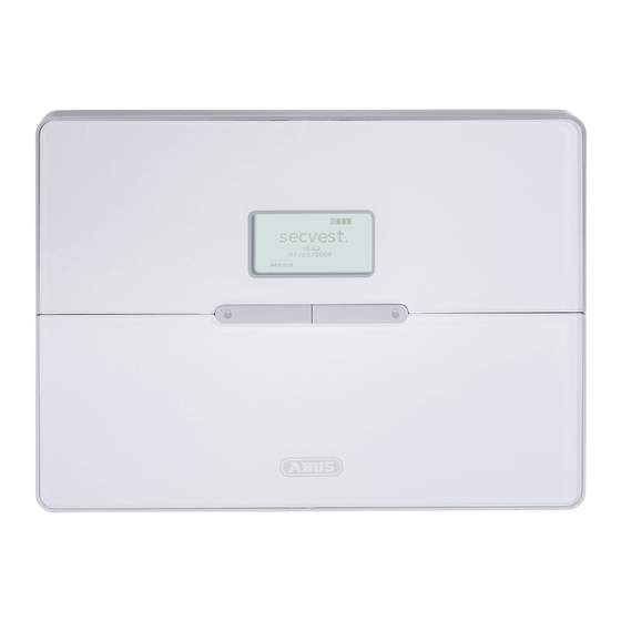
Abus Secvest 2WAY Installation Instructions Manual
Hide thumbs
Also See for Secvest 2WAY:
- Operating instructions manual (48 pages) ,
- Installation instructions manual (167 pages) ,
- Manual (60 pages)
Table of Contents
Advertisement
Quick Links
Advertisement
Table of Contents

Related Manuals for Abus Secvest 2WAY


Summary of Contents for Abus Secvest 2WAY
- Page 1 Secvest 2WAY I N S T A L L A T I O N I N S T R U C T I O N S BOM-No. 12000868...
-
Page 2: Preface
This wireless alarm centre is used to secure your property in combination with detectors and transmitters. Among others, it can be used to protect your company Many thanks for your purchase of the SECVEST 2WAY wireless alarm centre. This premises, house, garage, summer house or weekend cottage. -
Page 3: Table Of Contents
Transmitter ..............28 Contents Communication modules ........29 Preface ..................2 Modules and external sirens ........29 Introduction ................2 Accessories ..............30 Contents ................... 3 Wireless testing box ..........30 Example: Securing a single-family house .... 7 Safety information ........... 31 Cellar installation ............ - Page 4 First steps in the installer menu ......42 14.3.3 WAM as wireless transmitter / receiver ....61 11.1 Overview of menu items in the installer menu . 42 14.3.4 WAM as siren module ..........61 11.2 Adding detectors ............43 Arming station ............
- Page 5 Download settings ........... 74 19.21 Primary Telecoms ............ 84 Account Name ............74 19.22 Phone Book (Social Care) ........84 18.1 Connection Type ............74 19.23 Account Numbers ............. 84 18.2 Rings to Answer ............75 19.24 Report Type ............... 84 18.3 Answer on 1 ring .............
- Page 6 Walk Test ..............92 21.4 Detector Signals ............92 21.5 Ext Sirens ..............92 21.6 WAM Signal ............... 92 21.7 Arming Station ............93 21.8 Outputs ..............93 21.9 21.10 Telecommands ............93 21.11 Pendants ..............93 21.12 PA Detector ............... 93 21.13 Tag ................
-
Page 7: Example: Securing A Single-Family House
1. Example: Securing a single-family house This example can be used for better understanding of house security ‐ To protect your house so that you can still move around whilst the system is activated (external perimeter protection) ‐ To have a status display on each floor Planning ‐... -
Page 8: Cellar Installation
1.1 Cellar installation Number Installed components Abbr. Cellar Info module Motion sensor Water detector Smoke detector Opening detector Glass breakage detector... -
Page 9: Ground Floor Installation
1.2 Ground floor installation Installed components Abbr. Ground floor Secvest 2WAY Motion sensor Water detector Smoke detector Opening detector - with Glass breakage detector Wireless key switch... -
Page 10: Top Floor Installation
1.3 Top floor installation Installed components Abbr. OD + Top floor Control panel Internal siren Wireless motion sensor WLMS Wired motion sensor Water detector Smoke detector Opening detector WLMS Glass breakage detector Wired opening detector Info module External siren OD + WLMS WLMS... -
Page 11: Number Of Components
Abbr. Installed components Abbr. Cellar Total Info module Control panel Motion sensor Info module Water detector Secvest 2WAY Smoke detector Wireless key switch Opening detector External siren Glass breakage detector Internal siren Motion sensor WLMS Wired motion sensor Installed components Abbr. -
Page 12: Detector List
1.5 Detector list Create a detector list for the 50 zones after making your initial planning... -
Page 13: Installing The System
2.1 230 V ∼ 50 Hz mains connection 2. Installing the system The following pages describe basic system programming. A step-by-step guide of the most important aspects on the Secvest 2WAY system is Detach the cable relief points presented. and secure the power cable. -
Page 14: Pstn Telephone Connection
Coding “You are now in the installer menu” TAE N-plug Select the Detectors menu item. Select Add/Del Detectors. White Select Zone 01 Brown Pink Grey connection on Secvest 2WAY PSTN You will now be prompted to activate the Tamper contact... -
Page 15: Assigning The Zone Name
Enter letters and characters via the keypad. When using the smoke detector, press the test button and hold it until the alarm Letter-to-key assignment: sounds (about 10 seconds). Press the wall break contact on the opening detector. The Secvest display confirms successful training by showing the display: Detector assigned to: Wall break Test button... -
Page 16: Checking The Detector Range
3.2 Checking the detector range 3.3 Checking the signal strength of the detector The detector signal strength test is made in the same way as the walk test. The displayed signal strength corresponds to the reception strength of the last received signal on this detector. -
Page 17: Installing And Training The Info Module
Train the alarm centre to the info module. 3.4 Installing and training the info module In the installer menu: The example shows a house in four partitions. The status of each partition should be displayed on each floor. Each partition can be activated or deactivated separately. Therefore, an info module must be installed for each partition. -
Page 18: Accessing The Alarm Centre
3.5 Accessing the alarm centre In order to not trigger an alarm when leaving (Ext Time) or entering (Ent Time) the area, a delay time must be defined for accessing the centre in Partition 01. Access the installer menu and set the exit or entry delay under the “Partitions” menu item. -
Page 19: Internal Alarm Active (Prt Set All)
3.6 Internal alarm active (Prt Set All) This setting is used when the inside of the house should be accessed freely whilst being protected against break-ins from the outside. external surveillance The detectors must be configured so that created. Change Part Set to Yes The Part Set setting is displayed with I. -
Page 20: Forwarding Alarm Messages Over The Telephone (Speech Dialler)
3.7 Forwarding alarm messages over the telephone (speech dialler) This setting is used for informing the user over the telephone. Call up the installer menu and select the “Reporting” menu item. Installed microphone In the installer menu: The recording should contain the following information: menu item. - Page 21 The call sequence starts with number 01, then number 02 up to the “Follow me” Trigger Triggered by number. None Triggers do not trigger messages In the speech dialler menu: Fire Smoke detector Panic Panic transmitter Medical Emergency call transmitter, pendants Opening, motion, glass breakage and vibration 1 menu item.
-
Page 22: Informing Other Persons
3.8 Informing other persons 3.9 Signaller To prevent manipulation of the siren, it should be attached In the speech dialler menu: out of arm’s reach (at least 3 metres from the ground). Please also take local legislations into account. In some European countries, the use of external sirens is forbidden or the maximum alarm duration is restricted. -
Page 23: Configure A User
Select the trained Ext Siren. A message is displayed with the siren confirmation and the signal strength value. If the external siren should be activated when the relevant partition triggers a local or Leave this display by pressing Back. external alarm, then the partition must be set to Yes. 3.10 Configure a user If a siren has been trained, then the symbol is shown next to the... - Page 24 User menu Select the “User” menu item. You have a guest that may only access the ground floor. Now enter an access code for your guest. Enter a user name. Confirm the access code by repeating it. Confirm with OK. You now have the possibility of training diverse components for activation.
- Page 25 If you do not wish to train telecommands (remote control), then confirm by pressing No Telecommands… If you do not wish to train social care, then confirm by pressing No Social… If you do not wish to train panic transmitters, then confirm by pressing No PA… The user is added with this display.
-
Page 26: Scope Of Delivery
4. Scope of delivery Installation instructions Chip key (tag) Downloader CD Operating instructions Keyring Secvest 4 wireless alarm centre 2 x housing screws 2 x screws 8 x hole adapters 2 x 4.7 kΩ 2 x 2.2 kΩ 3 x wall plugs 6 x NiMH R6 AA (tension relief) 3 x screws... -
Page 27: Accessories (Not Included In Scope Of Delivery)
5. Accessories (not included in scope of delivery) 5.1 Detector Motion sensor Opening Seismic Glass breakage Smoke detector Alarm detector Fire alarm FU8350 detector sensor detector FU8340 FU8300 FU8310 FU8320 (CC) FU8380 FU8370 FU8321 (FSL) 5.2 Wired detector MK1010W FU7300 MK1300W with WKS... -
Page 28: Remote Controls
5.3 Remote controls Chip key (tag) Arming station Remote control Key switch with Wireless cylinder AZ5501 FU8110 FU8100 status display FU59xx FU8360 (PET) FU8165 5.4 Transmitter Emergency call Panic transmitter transmitter (pendant) FU8305 FU8390... -
Page 29: Communication Modules
5.5 Communication modules ISDN module GSM module IP module FU8020 FU8010 FU8030 5.6 Modules and external sirens Info module Wireless external siren Accessory module FU8200 FU8220 FU8210... -
Page 30: Accessories
5.7 Accessories 12 V / 1 A built-in PSU 6 V standby rechargeable battery for 55 mm 12 V / 1 A PSU for the accessory UP switch boxes FU3822 TVAC35200 module FU3821 5.8 Wireless testing box 868 MHz wireless testing PC cable FU3810 FU3801... -
Page 31: Safety Information
6. Safety information IMPORTANT WARNING Caution INFORMATION To avoid fire and injury, please note the following: Please observe the following precautionary measures to ensure trouble-free operation of your system. On burglar alarm centres in general: • Securely fasten the device in a dry location in the •... -
Page 32: Notes On Connection And Extension Options
7. Notes on connection and extension options Alarm centre characteristics: • The wireless alarm centre is the central part of an electronic 48 freely programmable wireless zones, all of which can be programmed as security system for protecting your property (e.g. apartment, follows: Normal Alarm, Final Exit, Entry Route, 24 Hour, Fire, Panic, Key Sw house, garage, shops etc.). -
Page 33: Notes On The Security System
8. Notes on the security system 8.2 Connections on the top part of the alarm centre High-frequency emission warning! The following diagram shows the connections on the top part of the alarm centre. The limit value of the emitted high-frequency signals for these components is below the European standard (considered as safe). -
Page 34: Connections On The Base Plate Of The Alarm Centre
8.3 Connections on the base plate of the alarm centre 8.5 Assembling the base plate The following diagram shows the connections on the base plate of the alarm centre. Fix the base plate to the wall as shown in the diagram. Ensure that the alarm centre is installed so that the rear is not screened by hidden metal. -
Page 35: Connecting The Alarm Centre To The 230 V Mains Supply
8.6 Connecting the alarm centre to the 230 V mains supply 8.7 Connecting wired detectors (optional) Connecting the alarm centre to the 230 V AC mains network is subject to national If wired components are connected to the wireless alarm, then connect them as regulations. -
Page 36: Connecting The Analogue Telephone Connection
8.8 Connecting the analogue telephone connection 8.10 Inserting the rechargeable batteries for emergency power supply Connection instructions for ISDN / GSM / ethernet and GPRS modules can be found Insert the six batteries correctly into the compartment. Replace the batteries every in chapter 11. -
Page 37: Closing The Alarm Centre
8.11 Closing the alarm centre 8.13 Final tasks Reconnect the top part to the base plate. Remember to connect the connection cable All connections are now made and the wireless alarm centre is ready for of the base plate to the alarm centre. At the same time, check that all other programming. -
Page 38: Explanation Of Terms
9. Explanation of terms Before starting to program the alarm centre, you should become familiar with the terms used. The following is an explanation of the possible zone types and their allocated attributes: 24 HOUR ZONE This zone always triggers an immediate alarm. If the wireless alarm centre is A zone is a detector that has been trained for the wireless alarm centre. - Page 39 KEY BOX SILENT ALARM This zone is mainly used in Scandinavia. If this zone is opened, the trigger is stored In the event of a silent alarm, the connected acoustic and optical signalling devices in the memory of the burglar alarm centre. The can also be transmitted via the are not activated.
-
Page 40: Overview Of The Alarm Centres
10. Overview of the alarm centres 1 – Chip key reader 2 – Graphic display Multiple-line display 3 – Integrated siren 4 – Activation button 5 – Deactivation button 6 – Control buttons 7 – Keypad alarm keys for panic, fire, medical and social call emergencies 8 –... - Page 41 11. Graphic display The graphic display informs you about all events concerning the wireless alarm system. The following is an overview of the different display messages and their meaning: The four black bars stand for the This symbol appears if a voice message four individual partitions of the exists that should be listened to.
-
Page 42: Installer Menu
12. Installer menu 12.1 First steps in the installer menu In the user mode, proceed as follows: The wireless alarm centre is configured in the installer menu. If you are in user mode, you must first change to the installer mode. Do this as follows: There are two ways of programming the wireless alarm centre: 7 8 9 0 Enter a valid installer code (default setting = 7890):... -
Page 43: Adding Detectors
Function Meaning Download Configure download settings Auto learn If this item is selected, you can walk through your property and activate the detectors one after the other (by triggering the tamper contacts). The detectors send a Reporting Configure telephone settings, define transmission types learn message and the alarm centre now automatically stores the book-in messages in sequence according to the zone locations. -
Page 44: Deleting The Detector Or Detector With Zone Information
If a detector has been trained, then the symbol is shown next to the zone number. In the installer menu: This display shows which zone the detector has been trained to, the zone type programmed for this zone, the partition that the detector monitors and the additional zone attributes. -
Page 45: Detector Already In Use
Some detectors do not have tamper contacts (e.g. smoke detectors) and only send an alarm (A). The display with the number of tested zones without tamper contacts remains. To delete the detector and the zone information, select the Default Zone menu item and confirm with Next Select Test Select Walk Test... -
Page 46: Adding The Zone 01 Detector Manually
Select the Delete All menu item. You will now be prompted to activate the Tamper contact Example: Motion sensor Tamper contact Confirm deletion by pressing Yes (wall break contact) 13.5 Adding the zone 01 detector manually In the installer menu: Display of the signal menu item. -
Page 47: Editing Detectors (Zones)
13.6 Editing detectors (zones) In the installer menu: menu item. Select the Edit Zones Select the Name menu item. The detector transmits its standard settings automatically to the alarm centre after training. This setting can be changed at any time. Delete the existing name (Zone 01) and assign a unique name for the zone (max. -
Page 48: Selecting The Zone Type
13.8 Selecting the zone type ENTRY ROUTE This zone does not trigger an alarm if an entry/exit zone has previously activated the The preset zone type can be changed here. Pay attention to the zone type descriptions entry delay time. An immediate alarm is triggered if no entry delay was previously in this chapter. -
Page 49: Selecting Partitions
KEY SW MOMENT Train a key switch (pulse) to the wireless alarm centre. Any change to this zone changes the state of the alarm centre from active to inactive or vice versa (following the delay time). KEY SW LATCHED A key switch (permanent) can be connected to the burglar alarm centre. Any change to this zone changes the state of the alarm centre from active to inactive or vice versa (following the delay time). -
Page 50: Selecting Zone Characteristics
13.10 Selecting zone characteristics The Soak Test function should only be set when the detector has a tendency of triggering false alarms. This function works automatically. To test the detector range, use the walk test function. Do not activate the detector test, as this function ensures that a message is stored in the memory and no alarms are triggered when the wireless alarm system is activated. -
Page 51: Outputs
14. Outputs The controller has 34 outputs. The first two outputs (O/P1 and O/P2) are wired outputs. Outputs 3 to 34 are wireless outputs. They can be accessed using a FU8210 accessory module. Select Add Output. Select (HW)Output 01 Switch outputs O/P1 and O/P2: Disconnected, single pole relay contacts DC: 24 V / 1 A AC: 120 V / 0.5 A... -
Page 52: Editing Outputs
Letter-to-key assignment: 14.2 Editing outputs The letters and characters can be selected by pressing the keys several times. The In the installer menu: cursor goes to the next position after around two seconds. menu item. Select the Edit Output Now edit Zone 01. Confirm the changes by pressing OK 14.4 Selecting the output type The output properties can be changed here. - Page 53 deactivated can be entered at the end (see the note Type Meaning below). Not Used This output is not in use and is never activated. FullSet RDY P1 - P4 This output is activated when the partition is ready to be (Exception: complete power loss).
-
Page 54: Example: "User Defined" Output Type
14.5 Example: “User Defined” output type After selecting the User Defined output type and entering the times, you can then connect the programmed output with a wired input (programmed as “Key Sw Latched”). In this way, the alarm centre can be activated and deactivated at a defined time. -
Page 55: Wam Outputs
14.7 WAM outputs In the installer menu: menu item. Select the Edit Output Assign a new name and finish data entry by pressing OK The WAM wireless outputs can be edited after training the WAM as a wireless transmitter or receiver (function 3). Please note that the disconnected WAM outputs have a maximum load of 500 mA at 24 V. -
Page 56: Other Devices
successful activation of the wireless alarm centre. 15. Other Devices Siren P1 - P4 This output is activated on local alarms in the selected partition for the defined siren duration. The following components can be added under this menu item: Strobe Set P1 - P4 This output is activated for a local alarm in the selected partition and remains active until the wireless alarm centre is... -
Page 57: External Siren
15.1 External siren When the sirens have been trained, the alarm centre beeps twice as confirmation. A message is displayed with the siren confirmation and the signal strength value. In the installer menu: Select Ext Sirens Leave this display by pressing Back. If a siren has been trained, then the symbol is shown next to the siren number. -
Page 58: Info Module/Int Siren
If the external siren should be activated when the relevant partition triggers a local or If the receiver beeps twice, the learn message was correctly received. End the learning external alarm, then the partition must be set to Yes. procedure by pressing Yes. Cancel the process by pressing No. The learn procedure is now started again. -
Page 59: Rdy-To-Set Led
15.2.2 Rdy-to-Set LED 15.3 Add WAM This function must also be set if the info module is equipped with properties of the “Ready” display. This signals that at least one zone in the partition is open (zones Please ensure that reserved outputs and zones are allocated to each connected with “Force Set”... - Page 60 Select the corresponding accessory module (WAM). In total, up to eight accessory modules can be trained. Select WAM 1. Select a module (e.g. WAM 1 When the WAM is trained, it also transmits its programming so that you can see the function in which the WAM has been trained under “View WAM”.
-
Page 61: Wam As Wireless Repeater
15.3.1 WAM as wireless repeater 15.3.4 WAM as siren module WAM function 1 WAM function 4 If the accessory module is trained with the wireless repeater function, then the wireless After configuring the WAM as a siren module, you will see a display in which you have repeaters whose signals are to be transmitted via this module must also be trained to to define the partition where the siren is to be activated. -
Page 62: Editing The Arming Station
Trigger the tamper contact on the arming station (see the station operating Select the function from the table and allocate it to the arming station key. Confirm the instructions). When the arming station has been trained, the wireless alarm centre selection by pressing Select. - Page 63 15.4.2. Arming station with new function 15.4.3. Switching outputs 15.4.3.1. Using the arming station The arming station can also be used outdoors (IP54). Using the “Instant Set” function, the alarm centre can be activated The outputs can be switched using the arming station or the remote control. without any exit delay after entry of the user code.
- Page 64 Now program the F3 function key on the arming station. Arming station (1) F3 (HW)Output 01 (HW)Output 02 Call up the installer menu. (RF)Output 03 (RF)Output 04 INSTALLER MENU OTHER DEVICES Other Devices Ext Sirens Select Back Info Module/Int Sirens Arming station Now select the (HW)Output 01 Select...
- Page 65 15.4.3.2. Using the remote control Output number TC01,T4:User01 Now program the double-arrow key on the remote control. (HW)Output... Internal activation Output number Select Back Select Back Now select the (HW)Output... Access the user menu as an administrator. (HW)Output 01 MENU System setting SYSTEM SETTINGS Toggle...
-
Page 66: Partitions
internal activation to “Instant Set”. 16. Partitions P.Set ER As Behaviour of the “Entry Route” zone at internal activation (ER remains ER or ER becomes FE). In the installer menu: Strobe Follow Set Behaviour of activation acknowledgement. The options are as follows: OFF –... -
Page 67: Exit Delays Of The Partition
16.2 Exit delays of the partition 16.5 Internal activation of the partition After entering the exit mode for the partition, a delay time must be entered in the Each individual partition can also be internally activated. This means that you can following cases: remain in the building without losing all-round protection. -
Page 68: System Options
Behaviour of activation acknowledgement. The options are as follows: Supervision Used for setting the response of the alarm centre in the OFF – No visual acknowledgement on external siren after successful activation (not event of supervision failure. internal). Jamming Used for setting the response of the alarm centre in the ON –... -
Page 69: Remote Control / Remote Access By Telephone
17.2 Remote control / remote access by telephone 17.3 Selecting a language Select the desired language. This function enables a user to give commands to the wireless alarm centre from a remote location using the telephone keypad. The available commands are as follows. 17.4 Default settings More information can be found in the operating manual. -
Page 70: Installer Code
17.6 Deactivation in the event of delays Select whether deactivation of the alarm system using the remote control is only possible when the delay time was previously started (trigger of entry or exit zone). If this function is deactivated, then the system can also be deactivated when the delay time is not running. -
Page 71: Siren Time
Select whether the siren is to start immediately or after the selected delay time following the triggering of a local or external alarm. When this option is activated, the wireless centre prevents the user from activating the system when a detector has lost contact with the wireless centre for more than 15 minutes. -
Page 72: Jamming
17.13 Jamming 17.16 Force Set Select whether the alarm system should display a warning in the case of jamming detection. If this function is enabled, a warning is shown on the display if jamming is detected. When On is selected, the zones with the “Z” zone attribute are automatically hidden when the alarm system or partition is activated (provided the zones are open). -
Page 73: Ip Network
the next group by a “dot”, e.g. “192.168.000.001”. 18. IP Network Press “* ” to enter the dot. When an ethernet or GPRS module is attached, this menu allows the user to allocate IP Port Number the wireless centre an individual IP address. This is then used for IP alarms or the IP Enter the port number or leave blank. -
Page 74: Download Settings
19.1 Account Name 19. Download settings Select the corresponding function. For a list of functions and their attributes, see the table below. Select “Download”. If no account name is entered here by the software, nothing is displayed here. 19.2 Connection Type Select whether the connection between the PC and the wireless centre should be Function Meaning... -
Page 75: Rings To Answer
19.3 Rings to Answer 19.5 Access Mode Select which functions are used for the remote maintenance access mode over remote Select when the wireless alarm centre should accept a call. To select a number of data transmission (see table). rings, press Select. Function Meaning Call out only... -
Page 76: Ip Network
19.7 IP Network 19.9 Modem Baud Rate If an ethernet module is attached to the wireless alarm centre, then it is possible for the Select the baud rate (bps) for data transmission. If you do not know the baud rate of downloader to communicate with the wireless alarm centre using the Internet protocol. -
Page 77: Alarms
20.1 ALARMS 20.2 Call Mode Select the corresponding function. For a list of functions and their attributes, see the Select the corresponding function. For a list of functions and their attributes, see the table below. table below. Function Meaning Function Meaning Call Mode Settings for reporting alarm messages. -
Page 78: Phone Book (Alarms)
20.6 Account Numbers 20.4 Phone Book (ALARMS) Enter the account number that you have received for transmitting from the command Select which number should be changed. Enter the callback number of the command centre. centre that you received for transmitting the respective report. Press the star key to Select which account number should be changed. -
Page 79: Report Type
20.7 Report Type Tamper Alarm Unset (see note 1) Set (see note 1) Select the report type to be used for digital alarm transmission to the command centre. Zone Omitted (see note 2) The command centre usually indicates which type of report to select. Medical Alarm The available report types are as follows: Key Box... -
Page 80: Sia Report Mode
Battery missing 20.10 SIA Report Mode Battery missing OK ISDN/GSM fault Select this, then select the Level of the transmission. The following table details which ISDN/GSM fault OK events should be transmitted for the SIA 1 report. PSTN fault PSTN fault OK Jamming Supervision fault Supervision fault OK... -
Page 81: Contact Id Reports
Technical alarm Technical alarm OK Power failure Power failure OK Reset Battery fault Battery fault OK Battery missing Battery missing OK 20.12 Contact ID Reports ISDN/GSM fault Select whether the restoration of a function (closing of an alarm zone, error clearance) ISDN/GSM fault OK should be transmitted to the command centre. -
Page 82: Static Test Call
If the function is enabled, the call is made every 24 hours following the last alarm. If this function is enabled, all zones in the alarm state are hidden. If the function transmission. is disabled, then this channel is also disabled until the alarm centre is deactivated and reset. -
Page 83: No Transmission
20.18 No Transmission 20.20 Call Mode 20.19 Social Care Select the corresponding function. For a list of functions and their attributes, see the table below. This setting must only be selected when transmitting to a social care unit using a digital protocol. For voice message transmission, select the next menu item (Configuring speech dialler). -
Page 84: Primary Telecoms
20.21 Primary Telecoms An account number can be eight characters long when reporting social care messages. Select which primary transmission path should be used. This transmission path is used When the Scancom or Scanfast report types are used (see below), then the wireless as long as transmission is possible using it. -
Page 85: Call Acknowledge
speech dialler, connect each message with the specific alarm type to be reported. Select a target set for each message. Each target then corresponds to one of the Social care messages can be triggered in the following ways: telephone numbers to be dialled (see also the overview of the “Reporting” menu point in the installer menu for speech diallers at the end of the manual). -
Page 86: Primary Telecoms
20.28 Primary Telecoms Please note that the last telephone number is designated as the Follow me number. The wireless centre shows this number in the user menu. The user can enter a new number in this field. This allows the user to forward all voice messages programmed Select which primary transmission path should be used. -
Page 87: Call Acknowledge
20.34 Alarm call with voice message After selecting a message, an overview of the phone numbers entered previously It may take several seconds until the text message is announced when an alarm call under “Phone Book” is displayed. If the telephone number has been given a name, with voice message is received. -
Page 88: Call Mode
20.36 Call Mode Press the star key to enter a dial pause. The dial pause is displayed as a comma. Each dial pause interrupts the dial procedure for 3 seconds. The display can then be used to enter a name for this number. The alarm centre shows these names in the This option is used to activate or deactivate SMS communications. -
Page 89: Destinations
20.42 Destinations Select a message where one or more phone numbers should be assigned. Select the corresponding function. For a list of functions and their attributes, see the table below. Function Meaning After selecting a message, an overview of the phone numbers entered previously Report Type Select the protocol specified by your SMS service centre. -
Page 90: Line Fault
20.43 Line Fault 21. Social Care This menu can be used to program the system so that it reacts with an acoustic or Select the corresponding function. For a list of functions and their attributes, see the silent alarm when the alarm centre determines a fault in the remote transmission lines. table below. -
Page 91: Monitoring Interval
Detector Signals Tests the signal strength of the trained detectors. 21.2 Monitoring Interval Ext Sirens Tests the signal strength of the external sirens. Tests the signal strength of the wireless accessory module. Arming Station Tests the signal strength of the arming station. Outputs Tests the outputs through manual activation. -
Page 92: Testing The Loudspeaker
22.2 Testing the loudspeaker 22.4 Walk Test A list of all detectors trained to the system is shown on the display. Activate the loudspeaker by pressing Play/Stop under the display. After confirming with Play/Stop, the loudspeaker is activated. You should now hear the voice messages. -
Page 93: Arming Station
22.8 Arming Station 23. Viewing the log A list of log displays can be found in the user manual. The test of the arming station signal is used for displaying the signal strength. The signal strength should be higher than 3. 22.9 Outputs A list of all outputs installed on the system is shown on the display. -
Page 94: Installing Additional Modules
the top part around and remove the four housing screws (1) on the bottom. Ensure that 25. Installing additional modules you also disconnect the loudspeaker cable and the battery supply cable (2). Before connecting the ISDN / GSM / ethernet / GPRS module to the alarm centre, disconnect the electric power supply. -
Page 95: Fitting The Isdn Module
26. Fitting the ISDN module 27. Fitting the GSM module Insert the ISDN module carefully and exactly into the base of the ISDN module. Ensure Before inserting the GSM module, insert a SIM card into the GSM module. Any SIM that all base feet are correctly attached to the base holder. -
Page 96: Fitting The Ethernet Module
28. Fitting the ethernet module 29. Fitting the GPRS module Insert the ethernet module carefully and exactly into the base of the module. Ensure that all base feet are correctly attached to the base holder. Before inserting the GPRS module, insert a SIM card into the GPRS module. Any SIM cards who support this service and whose PIN code can be disabled are suitable (or SIM cards with a PIN changed to “0000”). -
Page 97: Final Tasks
30. Final tasks Open the top part, but this time do not loosen the connecting cable from the base plate. Instead, plug one end of the USB cable into the USB port (1) of the alarm centre. Finally, plug the siren plug from the cover of the top part back into the PCB and replace the tamper contact spring. -
Page 98: Programming
32.2 Programming Alarm centre behaviour in the event of power failure To program the system, install the downloader program from the software CD supplied. The current version of this program can also be downloaded from the When deactivated, a message is shown in the alarm centre display Security Center website. -
Page 99: Declaration Of Conformity
Communication This product is suitable for use in systems that are constructed according to the Class This product can be connected to an analogue telephone connection (PSTN) or an 2X and Environment Class II requirements in PD 6662 : 2004. This product meets the analogue extension connection. -
Page 100: Glossary
35. Glossary When required, strobes or signals are activated by the system in Signaller the event of an alarm (usually in combination). Short Message Service – Telecommunication service used for Term / Explanation sending text messages. Now also available on landlines in abbreviation addition to GSM mobile phones. - Page 101 Amendments to the operating manual (UK) Secvest 2WAY FU8006 S/W ≥ 5.04.22 A1 -...
- Page 102 We constantly develop our product range in order to provide our customers with optimal products incorporating state-of-the-art technology. The new software release for the Secvest 2WAY includes optimised workflows and an extended function range. These improvements can be found in the following document.
- Page 103 3. New menu items in Installer Menu 3.1. Secvest Key 2WAY wireless cylinder, item no. FU59xx Installer Menu Other Devices Secvest Key ADD/DEL Door Lock EDIT Door Lock • Adding and removing Key devices A maximum of four Secvest Key 2WAY wireless cylinders can be trained. Installer Menu Other Devices Secvest Key...
- Page 104 Secvest Key 2WAY can be tested here. “Unlocked” is shown on the Secvest 2WAY display when the door is unlocked. “Locked” is shown when the button on the Secvest Key 2WAY wireless cylinder is pressed and the door is then locked.
- Page 105 3.3. Tamper alarm Installer Menu System Options Send unset Tampers Disabled Enabled • Factory setting: Disabled • When “Enabled” is selected, tamper alarms are transmitted over the selected communication method, even when the alarm centre is deactivated. This applies to ALARMS, SPEECH DIALLER and SMS communication.
- Page 106 3.5. Customer ID for alarm communication to a social care service centre Installer Menu Reporting Social Care Account Numbers Account No P 1 Account No P 2 Account No P 3 Account No P 4 • “P” (partition) has now been added (previously “Account No 1” etc.). •...
- Page 107 4. Software changes 4.1. “Normal Alarm” zone type with FTS 96 E function To use the FTS 96 E wireless window lock (item no. FU841x) or the FTS 96 wireless upgrade set (item no. FU8402), program the “Normal Alarm” zone type in the alarm centre. •...
- Page 108 4.3. New operating mode for social care messages • An alarm cancellation using the pendant is no longer possible within the 30 second guard time. Earlier, an alarm was cancelled by pressing the button a second time within the guard time. •...
- Page 109 4.4. Zone name prompts This function is activated as follows and zone names are recorded: User Menu Facilities On/Off Zone Name Prompts Enabled The following additional prompt is then announced: • With opened zone “The System cannot set” + “<Zone name prompts>” When several zones are open, the zone with the smallest zone number is also announced.
- Page 110 A1 -...
- Page 111 Amendments to the operating manual (UK) Secvest 2WAY FU8006 S/W ≥ 5.05.30 A2 -...
- Page 112 We constantly develop our product range in order to provide our customers with optimal products incorporating state-of-the-art technology. The new software release for the Secvest 2WAY includes optimised workflows and an extended function range. These improvements can be found in the following document.
- Page 113 3. New menu items in Installer Menu 3.1. FTS 96 E Detector, additional attribut for “Normal Alarm” zone type Installer Menu Detectors Edit Zones Attributes Dis. Sabotage Yes /No • Factory setting: No • If “Yes” is selected, sabotage monitoring on the FTS 96 E wireless window protection system is switched off when the alarm system is deactivated.
- Page 114 3.3. Outputs - additional “Jamming” output type Installer Menu Outputs Edit Outputs Type Jamming • The corresponding output switches when jamming is detected. 3.4. Communication , SPEECH DIALLER, additional “Jamming” event type Installer Menu Reporting Speech Dialler Report Triggers Message x Trigger x Jamming •...
Need help?
Do you have a question about the Secvest 2WAY and is the answer not in the manual?
Questions and answers