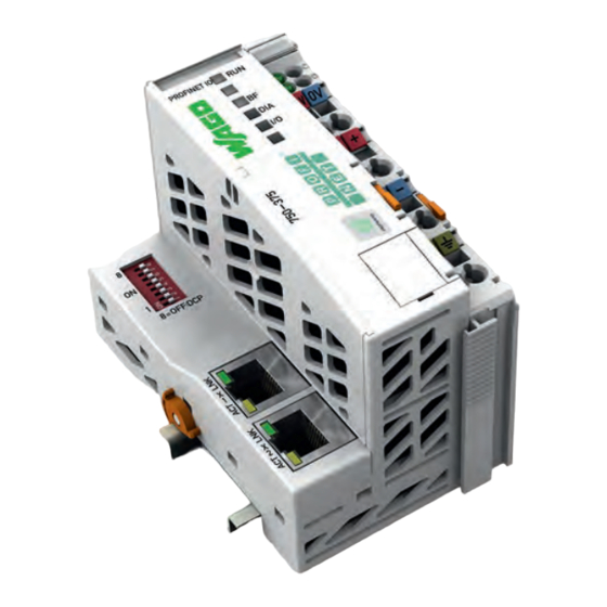
WAGO -I/O-SYSTEM 750 Manual

WAGO -I/O-SYSTEM 750 Manual

Profinet io advanced fieldbus coupler, 2-port switch, 100 mbit/s, digital, analog and complex signals
Hide thumbs Also See for WAGO-I/O-SYSTEM 750:
Table of Contents
  • Deutsch

    • Table of Contents
    • 1 Notes about this Documentation

      • Validity of this Documentation
      • Copyright
      • Tabelle 1: Variations
      • Symbols
      • Number Notation
      • Font Conventions
      • Table 2: Number Notation
      • Table 3: Font Conventions
      • Abbreviations and Terms
      • Table 4: Abbreviations and Terms Used in this Manual
    • 2 Important Notes

      • Legal Bases
      • Subject to Changes
      • Personnel Qualifications
      • Use of the 750 Series in Compliance with Underlying Provisions
      • Technical Condition of Specified Devices
      • Safety Advice (Precautions)
    • 3 System Description

      • Figure 1: Fieldbus Node (Example)
      • Manufacturing Number
      • Hardware Address (MAC ID)
      • Figure 2: Labeling on the Side of a Component (Example)
      • Figure 3: Example of a Manufacturing Number
      • Component Update
      • Storage, Assembly and Transport
      • Assembly Guidelines/Standards
      • Power Supply
      • Isolation
      • Figure 4: Isolation for Fieldbus Couplers/Controllers (Example)
      • System Supply
      • Connection
      • Figure 5: System Supply for Standard Fieldbus Coupler/Controller and Extended ECO Couplers
      • Dimensioning
      • Figure 6: System Voltage for Standard Couplers/Controllers and Extended ECO Couplers
      • Table 5: Alignment
      • Field Supply
      • Connection
      • Figure 7: Field Supply for Standard Couplers/Controllers and Extended ECO Couplers
      • Table 6: Caption for " Field Supply (Sensor/Actuator) for Standard Couplers/Controllers and Extended ECO Couplers
      • Fusing
      • Figure 8: Supply Module with Fuse Carrier (Example 750-610)
      • Table 7: Power Supply Modules
      • Figure 9: Removing the Fuse Carrier
      • Figure 10: Opening the Fuse Carrier
      • Figure 11: Change Fuse
      • Figure 12: Fuse Modules for Automotive Fuses, Series 282
      • Figure 13: Fuse Modules for Automotive Fuses, Series 2006
      • Figure 14: Fuse Modules with Pivotable Fuse Carrier, Series 281
      • Figure 15: Fuse Modules with Pivotable Fuse Carrier, Series 2002
      • Supplementary Power Supply Regulations
      • Figure 16: Power Supply Concept
      • Table 8: Filter Modules for 24 V Supply
      • Supply Example
      • Figure 17: Supply Example for Standard Couplers/Controllers and Extended ECO Couplers
      • Table 9: Caption for Figure "Supply Example for Fieldbus Coupler/Controller
      • Power Supply Unit
      • Table 10: WAGO Power Supply Unit (Selection)
      • Grounding
      • Grounding the DIN Rail
      • Framework Assembly
      • Insulated Assembly
      • Table 11: WAGO Ground Wire Terminals
      • Grounding Function
      • Figure 18: Carrier Rail Contact (Example)
      • Shielding
      • General
      • Bus Cables
      • Signal Lines
      • WAGO Shield Connecting System
      • Figure 19: Example of the WAGO Shield Connecting System
      • Figure 20: Application of the WAGO Shield Connecting System
    • 4 Device Description

      • Fieldbus Coupler Properties
      • General Specifications
      • PROFINET IO Properties
      • Table 12: PROFINET IO Properties and Specifications
      • Implemented Protocols and Services
      • Supported Profiles for PROFINET IO
      • View
      • Table 13: Legend to the View PROFINET IO Advanced Fieldbus Coupler
      • Connectors
      • Device Supply
      • Figure 22: Device Supply
      • Fieldbus Connection
      • Figure 23: RJ-45 Connector
      • Table 14: RJ-45 Connector and RJ-45 Connector Configuration
      • Display Elements
      • Figure 24: Display Elements
      • Table 15: Display Elements Fieldbus Status
      • Table 16: Display Elements Node Status
      • Table 17: Display Elements Supply Voltage
      • Figure 25: Display Elements Fieldbus Connection RJ-45
      • Table 18: Display Elements Fieldbus Connection RJ-45
      • Operating Elements
      • Service Interface
      • Figure 26: Service Interface (Closed and Opened Flap)
      • Table 19: Legend for Figure "Service Interface (Closed and Opened Flap)
      • DIP Switch
      • Figure 27: DIP Switch (for Example Setting "0")
      • Table 20: DIP Switch - Explanation of the 8 Slide Switches
      • Table 21: Example DIP Switch Setting
      • Technical Data
      • Device Data
      • Table 22: Technical Data - Device Data
      • System Data
      • Supply
      • Accessories
      • Connection Type
      • Table 23: Technical Data - System Data
      • Table 24: Technical Data - Supply
      • Table 25: Technical Data - Accessories
      • Table 26: Technical Data - Field Wiring
      • Table 27: Technical Data - Power Jumper Contacts
      • Climatic Environmental Conditions
      • Table 28: Technical Data - Internal Bus
      • Table 29: Technical Data - Climatic Environmental Conditions
      • Approvals
      • Standards and Guidelines
    • 5 Mounting

      • Installation Position
      • Total Extension
      • Mounting Onto Carrier Rail
      • Carrier Rail Properties
      • WAGO DIN Rail
      • Spacing
      • Figure 28: Spacing
      • Table 30: WAGO DIN Rail
      • Mounting Sequence
      • Inserting and Removing Devices
      • Inserting the Fieldbus Coupler/Controller
      • Figure 29: Unlocking Lug Standard Fieldbus Coupler/Controller (Example)
      • Figure 30: Unlocking Lug of Extended ECO Fieldbus Coupler (Example)
      • Removing the Fieldbus Coupler/Controller
      • Figure 31: Unlocking Lug ECO Coupler
      • Inserting the I/O Module
      • Figure 32: Insert I/O Module (Sample)
      • Figure 33: Snap the I/O Module into Place (Sample)
      • Removing the I/O Module
      • Figure 34: Removing the I/O Module (Sample)
    • 6 Connect Devices

      • Data Contacts/Internal Bus
      • Figure 35: Data Contacts
      • Power Contacts/Field Supply
      • Figure 36: Example for the Arrangement of Power Contacts
      • Connecting a Conductor to the CAGE CLAMP
      • Figure 37: Connecting a Conductor to a CAGE CLAMP
    • 7 Function Description

      • Device Start-Up and Initialization
      • Switch Port Settings
      • Figure 38: Fieldbus Coupler Operating System
      • Identification and Maintenance Data Sets (I&M)
      • Table 31: Identification and Maintenance Data Sets (I&M)
      • Process Data Architecture
      • Basic Structure
      • Allocation of the Input and Output Data
      • Figure 39: Allocation of the Input and Output Data
      • Process Data Qualifiers in Telegrams for PROFINET IO
      • One Byte Ioxs Process Data Qualifiers
      • Two Byte Ioxs Process Data Qualifiers
      • Examples of One and Two Byte Ioxs Process Data Qualifiers
      • Table 32: Example 1 for Process Data Qualifiers for 2-Channel Digital Input
      • Table 33: Example 2 for Process Data Qualifiers for 2-Channel Digital Output Modules with Diagnostics
      • Table 34: Example 3 for Process Data Qualifiers for 2-Channel Analog Intput and
      • Table 35: Example 4 for Process Data Qualifiers for Special-Purpose Modules, SSI Sensor Interface
      • Configuration Limits
      • Minimum Configuration
      • Maximum Configuration
      • Flexible Configuration of Digital I/O Modules
      • Packaging Information from Digital Input and Output Modules
      • Rules for Packaging Digital Information
      • Example of Packaging Digital Information
      • Figure 40: Output Process Data in the Frame IOC  IOD
      • Figure 41: Input Process Data in the Frame IOD  IOC
      • Table 36: Example for a Station with the Following Selected Submodules
      • Possible Errors When Packaging Digital Information
      • Variation of Physical Peripheral Layout
      • Exemplary Maximum Configuration
      • Physical Option Modules
      • Figure 42: Exemplary Maximum Configuration
      • Figure 43: Exemplary Usage of Physical Option Modules
      • Virtual Option Modules
      • Combination of Physical and Virtual Option Modules
      • Figure 44: Exemplary Usage of Virtual Option Modules
      • Figure 45: Usage of Option Module Without Physical Slot Reservation
      • Station Characteristics Using Option Modules
      • Connection Phase
      • Figure 46: Usage of Option Module with Physical Slot Reservation
      • Process Data Handling
      • Identification
      • I&M Data Sets
      • Diagnostics
      • I/O Module Distribution to Several Ars (Shared Device)
      • Using Fail-Safe I/O Modules (Profisafe V2)
      • Individual Parameterization of I/O Modules Via Ipar Server
      • Figure 47: Ipar Server
      • Table 38: Legend for the Ipar Server Figure
      • Controlling Digital and Analog Output Modules Per Profienergy
      • Hardware
      • Functions
      • Addressing
      • Firmware Update
    • 8 Commissioning

      • General Procedure
      • Procedure Description
      • Real Time Data Exchange Establishment
      • Perform Configuration Steps
      • GSD File
      • Parameterization
      • Parameterization of the Station Proxy (DAP)
      • Restart on K-Bus Failure
      • Diagnostics of External Module/Channel Errors
      • Internal Data Bus Extension
      • Table 39: Parameterization - Overview of Attributes for the Station Proxy (DAP)
      • Table 40: Parameterization DAP - Attribute Restart on K-Bus Failure
      • Table 41: Parameterization DAP - Attribute Diagnostics of External Module/Channel Errors
      • Table 42: Parameterization DAP - Attribute Internal Data Bus Extension
      • Response to PROFINET IO Failure
      • Response to K-Bus Failure
      • Activation of the Integrated Webserver
      • Activation of Firmware Updates
      • Table 43: Parameterization DAP - Attribute Response to PROFINET IO Failure
      • Table 44: Parameterization DAP - Attribute Response to K-Bus Failure
      • Table 45: Parameterization DAP - Attribute Webserver
      • Table 46: Parameterization DAP - Attribute WAGO-Service (TCP Port 6626)
      • Activation of the Station-Wide Profienergy Functionality
      • Parameterization of the I/O-Modules
      • Table 47: Parameterization DAP - Attribute Minimal Pause Time (Profienergy)
      • PROFINET Connection
      • Structure of the Application and Communication Relationships (AR and CR)
      • Connection Response with no Configuration Differences
      • Connection Response with Configuration Differences
      • Parameterization of Submodule's Data Sets
      • End of the Parameterization Phase and Operational Readiness
      • Data Exchange
      • Send Cycle Times (Update Time)
      • Connection Monitoring
      • Table 48: Send Cycle Time as a Function of RT Class, Transmit Clocking and Scaling
      • Demand Data Exchange (Acyclic Communication)
    • 9 Web-Based Management (WBM)

      • General Structure of WBM
      • Figure 48: Structure of WBM Pages, Example: WBM Page "Information
      • Status Area
      • Figure 49: WBM Pages - Status Area
      • Table 49: Legend for the Indicators in the Status Area
      • Information
      • Figure 50: WBM Page „Information
      • Table 50: Parameter Description of WBM Page "Information
      • Ethernet
      • Figure 51: WBM Page"Ethernet
      • Table 51: Description of the Parameters of the WBM Page "Ethernet
      • Tcp/Ip
      • Diagnostics
      • Figure 52: WBM Page „TCP/IP
      • Table 52: Description of the Parameters of the WBM Page "TCP/IP
      • Administration
      • Figure 53: WBM Page "Diagnostics
      • Figure 54: WBM Page "Administration
      • Table 53: Parameter Description of the WBM Page "Administration
      • Connection Errors
    • 10 Diagnostics

      • LED Signaling
      • Figure 55: Display Elements
      • Figure 56: Display Elements Fieldbus Connection RJ-45
      • Table 54: LED Assignment for Diagnostics
      • Evaluating the Fieldbus Status
      • Table 55: Fieldbus Diagnostics - Solution in Event of Error
      • Table 56: Diagnostics of the Fieldbus Status on the Fieldbus Connection - Solution in Event of Error
      • Evaluating the Node Status
      • Table 57: Node Status Diagnostics - Solution in Event of Error
      • Figure 57: Node Status - I/O LED Signaling
      • Figure 58: Error Message Coding
      • Table 58: Blink Code- Table for the I/O LED Signaling, Error Code 1
      • Table 59: Blink Code Table for the I/O LED Signaling, Error Code 2
      • Table 60: Blink Code Table for the I/O LED Signaling, Error Code 3
      • Table 61: Blink Code Table for the I/O LED Signaling, Error Code 4
      • Table 62: Blink Code Table for the I/O LED Signaling, Error Code 5
      • Table 63: Blink Code Table for the 'I/O' LED Signaling, Error Code 6
      • Table 64: Blink Code Table for the 'I/O' LED Signaling, Error Code 7
      • Table 65: Blink Code Table for the I/O LED Signaling, Error Code 9
      • Table 66: Blink Code Table for I/O LED Signaling, Error Code 10
      • Table 67: Blink Code Table for I/O LED Signaling, Error Code 12
      • Evaluating Power Supply Status
      • Error Response
      • Fieldbus Failure
      • Table 68: Power Supply Status Diagnostics - Solution in Event of Error
      • Internal Data Bus Failure
      • PROFINET IO Diagnostics
      • Table 69: Diagnosis of Fieldbus Failure
      • Diagnosis Data Sets
      • Structure of the Standardized Diagnosis Data Sets
      • Table 70: Retrievable Record Data Sets for Diagnostics
      • Table 71: Structure Head for the Diagnostic Data
    • 11 Fieldbus Communication

      • Standard ETHERNET Protocols
      • IP, TCP and HTTP
      • Dcp
      • Lldp
      • Mrp
      • Snmp
      • Profinet Io
      • General
      • Cabling
      • PROFINET IO Device Classes
      • Addressing
      • Figure 59: PROFINET Principle
      • PROFINET Communication Principle
      • Data Traffic
      • Communication Connection
      • Application and Communication Relationship (AR, CR)
      • System Start-Up
      • Data Exchange
      • Using Configuration Software
      • Hardware Configuration in the Configuration Software
      • Parameterization in the Configuration Software
      • Communication Configuration in the Configuration Software
    • 12 O Modules

    • 13 Use in Hazardous Environments

      • Marking Configuration Examples
      • Marking for Europe According to ATEX and IEC-Ex
      • Figure 60: Side Marking Example for Approved I/O Modules According to ATEX and Iecex
      • Figure 61: Text Detail - Marking Example for Approved I/O Modules According to ATEX and Iecex
      • Table 72: Description of Marking Example for Approved I/O Modules According to ATEX and Iecex
      • Table 74: Description of Marking Example for Approved I/O Modules According to
      • Figure 62: Side Marking Example for Approved Ex I I/O Modules According to ATEX and Iecex
      • Figure 63: Text Detail - Marking Example for Approved Ex I I/O Modules According to ATEX and Iecex
      • Table 73: Description of Marking Example for Approved Ex I I/O Modules According to ATEX and Iecex
      • Marking for America According to NEC 500
      • Figure 64: Side Marking Example for I/O Modules According to NEC 500
      • Figure 65: Text Detail - Marking Example for Approved I/O Modules According to
      • Installation Regulations
      • Special Conditions for Safe Use (ATEX Certificate TÜV 07 ATEX 554086 X)
      • Special Conditions for Safe Use (ATEX Certificate TÜV 12 ATEX 106032 X)
      • Special Conditions for Safe Use (IEC-Ex Certificate TUN 09.0001
      • Special Conditions for Safe Use (IEC-Ex Certificate Iecex TUN 12.0039 X)
      • Special Conditions for Safe Use According to ANSI/ISA
    • 14 Appendix

      • Module and Submodule Types of the I/O-Modules
      • Digital Input Modules
      • Table 75: Module Types - Digital Input Modules
      • Digital Output Modules
      • Table 76: Submodule Types and Data Lengths - Digital Input Modules
      • Table 77: Module Types - Digital Output Modules
      • Table 78: Submodule Types and Data Lenghts - Digital Output Modules
      • Digital Input/Output Modules
      • Table 79: Module Types - Digital Input/Output Modules
      • Analog Input Modules
      • Table 80: Submodule Types and Data Lengths - Digital Input/Output Modules
      • Table 81: Module Types - Analog Input Modules
      • Table 82: Submodule Types and Data Lengths - Analog Input Modules
      • Analog Output Modules
      • Table 83: Module Types - Analog Output Modules
      • Table 84: Submodule Types and Data Lengths - Analog Output Modules
      • Specialty Modules
      • Up/Down Counter
      • Table 85: Module Types - Up/Down Counter
      • Table 86: Submodule Types and Data Lengths - Up/Down Counter
      • 2-Channel Pulse Width Modules
      • Distance and Angle Measurement Modules
      • Table 87: Module Types - 2-Channel Pulse Width Output Modules
      • Table 88: Submodule Types and Data Lengths - 2-Channel Pulse Width Output
      • Table 89: Module Types - Distance and Angle Measurement Modules
      • Serial Interfaces
      • Table 90: Submodule Types and Data Lengths - Distance and Angle Measurement
      • Table 91: Modultypen - Serial Interfaces
      • Table 92: Submodule Types and Data Lengths - Serial Interfaces
      • DC-Drive Controller
      • RTC Module
      • Table 93: Module Types - DC-Drive Controller
      • Table 94: Submodule Types and Data Lengths - DC-Drive Controller
      • Table 95: Module Types - RTC Module
      • DALI/DSI Master and DALI Multi-Master Modules
      • AS-Interface Master Modules
      • Table 96: Submodule Types and Data Lengths - RTC Module
      • Table 97: Module Types - DALI/DSI Master and DALI Multi-Master Modules
      • Table 98: Submodule Types and Data Lengths - DALI/DSI Master and DALI
      • Table 99: Module Types - AS-Interface Master Modules
      • RF Modules
      • Table 100: Submodule Types and Data Lengths - AS-Interface Master Modules
      • Table 101: Module Types - RF Modules
      • 14.1.6.10 MP-Bus Master Modules
      • 14.1.6.11 Vibration Monitoring
      • Table 102: Submodule Types and Data Lengths - RF Modules
      • Table 103: Module Types - MP-Bus Master Modules
      • Table 104: Submodule Types and Data Lengths - MP-Bus Master Modules
      • Table 105: Module Types - Vibration Monitoring
      • 14.1.6.12 Safety Modules Profisafe V2
      • 14.1.6.13 Stepper Modules
      • Table 106: Submodule Types and Data Lengths - Vibration Monitoring
      • Table 107: Module Types - Safety Modules Profisafe V2
      • Table 108: Submodule Types and Data Lengths - Safety Modules Profisafe V2
      • Table 109: Module Types - Stepper Modules
      • I/O-Link Master (from FW 03)
      • CAN Gateway (from FW 03)
      • Proportional Valve Module (from FW 03)
      • Table 110: Submodule Types and Data Lengths - Stepper Modules
      • System Modules
      • Power Supply Modules
      • Parameters of the I/O Modules
      • Digital Input Modules (DI)
      • Table 111: Module Types - Power Supply Modules
      • Table 112: Submodule Types and Data Lengths- Power Supply Modules
      • Table 113: Parameterization - Overview of Attributes for Digital Input Modules
      • Table 114: Parameterization DI, DIA - Attributes "Channel Diagnosis
      • Table 115: Parameterization DI, DIA - Attributes "Diagnosis: External Fault
      • Digital Output Modules (DO)
      • Table 116: Parameterization - Overview of Attributes for Digital Output Modules
      • Table 117: Parameterization DO - Attributes "Substitute Value Behavior
      • Table 118: Parameterization DO - Attribute "Substitute Value (1 Byte)
      • Digital Output Modules with Diagnostics (DO, DIA)
      • Table 119: Parameterization - Overview of Additional Attributes for Digital Output Modules with Diagnostics (DO, DIA)
      • Table 120: Parameterization DO, DIA - Attribute "Channel Diagnosis
      • Table 121: Parameterization DO, DIA - Attribute "Diagnosis: External Fault
      • Table 122: Parameterization DO, DIA - Attribute "Diagnosis: Short Circuit
      • Profienergy Submodules (DO, PE)
      • Table 123: Parameterization DO, DIA - Attribute "Diagnosis: Line Break
      • Table 124: Parameterization - Overview of Additional Attributes for Profienergy Submodules (DO, PE)
      • Table 125: Parameterization DO, PE - Attribute "Minimal Pause Time
      • Table 126: Parameterization DO, PE - Attribute "Pause Output State
      • Analog Input Modules
      • Table 127: Parameterization - Overview of Attributes for Analog Input Modules
      • Table 128: Parameterization AI - Attribute "Channel Diagnosis
      • Table 129: Parameterization AI - Attribute "Diagnosis: External Fault
      • Table 130: Parameterization AI - Attribute "Diagnosis: Measuring Range
      • Table 131: Parameterization AI - Attribute "Diagnosis: Measuring Range
      • Table 132: Parameterization AI - Attribute "Diagnosis: Line Break
      • Table 133: Parameterization AI - Attribute "Diagnosis: Short Circuit
      • Special AI Module Types (AI, RTD, TC)
      • Table 134: Parameterization AI - Attribute "Diagnosis: Lower Limit Value Exceeded
      • Table 135: Parameterization AI - Attribute "Diagnosis: Upper Limit Value Exceeded
      • Table 136: Parameterization AI - Attribute "Lower User Limit
      • Table 137: Parameterization AI - Attribute "Upper User Limit
      • Table 138: Parameterization - Overview of Additional Attributes for Special AI
      • Table 139: Parameterization 2AI, RTD, TC - Attribute "User Scaling
      • Table 140: Parameterization 2AI, RTD, TC - Attribute "User Offset
      • Table 141: Parameterization 2AI, RTD, TC - Attribute "User Gain
      • Table 142: Parameterization 2AI, RTD, TC - Attribute "Vendor Scaling
      • Table 143: Parameterization 2AI, RTD, TC - Attribute "Watchdog Timer
      • Table 144: Parameterization 2AI, RTD, TC - Attribute "Vendor Scaling
      • Table 145: Parameterization 2AI, RTD, TC - Attribute "Status Flags
      • Table 146: Parameterization 2AI, RTD, TC - Attribute "Filter
      • Table 147: Parameterization AI, RTD 461- Attribute "Filter Constant
      • Table 148: Parameterization AI, RTD 481- Attribute "Filter Constant
      • Table 149: Parameterization AI, TC - Attribute "Filter Constant
      • Table 150: Parameterization 2AI, RTD 461, 481 - Attribute "Sensor Type
      • Table 151: Parameterization 2AI, RTD - Attribute "Overrange Protection
      • Table 152: Parameterization 2AI, RTD 463 - Attribute "Sensor Type
      • Table 153: Parameterization 4AI, RTD 464 - Attribute "Sensor Type
      • Table 154: Parameterization 4AI, RTD 464/020-000 - Attribute "Sensor Type
      • Table 155: Parameterization 2AI, RTD 464 - Attribute "Connection Type
      • Table 156: Parameterization AI, PM 494 - Attribute "DC Measurement
      • Table 157: Parameterization 2AI, RTD 461, 481 - Attribute "Connection Type
      • Table 158: Parameterization 2AI, TC - Attribute "Sensor Type
      • Table 159: Parameterization AI, TC - Attribute "Wire Break Detection
      • Table 160: Parameterization AI, TC - Attribute "Check Lower Measurement Range Limit
      • Table 161: Parameterization AI, TC - Attribute "Cold Junction Compensation
      • Table 162: Parameterization AI, 3 PM - Attribute "Watchdog
      • Table 163: Parameterization AI, 3 PM - Attribute "Nom. Frequency Power Supply
      • Table 164: Parameterization AI, 3 PM 495 - Attribute "Identifier Rogowski Coils
      • Table 165: Parameterization AI, 3 PM - Attribute "Peak Value Phase
      • Table 166: Parameterization AI, 3 PM - Attribute "Autoreset Min./Max. Value
      • Table 167: Parameterization AI, 3 PM - Attribute "User Scaling
      • Table 168: Parameterization AI, 3 PM - Attribute "Scaling Energy Consumption
      • Table 169: Parameterization AI, 3 PM - Attribute "Scaling Energy Consumption
      • Table 170: Parameterization AI, 3 PM - Attribute "Storage Interval Energy [S]
      • Table 171: Parameterization AI, 3 PM - Attribute "Current Transformer Ratio
      • Table 172: Parameterization AI, 3 PM - Attribute "Peak Value Meas. Interval
      • Analog Output Module (AO)
      • Table 173: Parameterization AI, 3 PM - Attribute "Min./Max. Reset Interval
      • Table 174: Parameterization - Overview of Attributes for Analog Output Modules
      • Table 175: Parameterization AO - Attribute "Substitute Value Behavior
      • Analog Output Module with Diagnostics (AO, DIA)
      • Table 176: Parameterization AO - Attribute "Substitute Value (2 Byte)
      • Table 177: Parameterization - Overview of Additional Attributes for Analog Output Modules with Diagnostics (AO, DIA)
      • Table 178: Parameterization AO, DIA - Attribute "Channel Diagnosis
      • Table 179: Parameterization AO, DIA - Attribute "Diagnosis: Short Circuit
      • Table 180: Parameterization AO, DIA - Attribute "Diagnosis: Undervoltage
      • Special AO Module Types with Parameter Channel
      • Table 181: Parameterization AO, DIA - Attribute "Diagnosis: Overtemperature
      • Table 182: Parameterization AO, DIA - Attribute "Diagnosis: Error
      • Table 183: Parameterization AO, DIA - Attribute "Diagnosis: External Fault
      • Table 184: Parameterization - Overview of Additional Attributes for Special AO Module Types with Parameter Channel(AO, 562, 563)
      • Table 185: Parameterization AO, 562, 563 - Attribute "User Scaling
      • Table 186: Parameterization AO, 562, 563 - Attribute "Calibration
      • Table 187: Parameterization AO, 562, 563 - Attribute "Number Representation
      • Table 188: Parameterization AO, 562, 563 - Attribute "Operating Mode
      • Table 189: Parameterization AO, 562, 563 - Attribute "On Exceeding User Limits
      • Profienergy Submodules (AO, PE)
      • Table 190: Parameterization AO, 562, 563 - Attribute "Output
      • Table 191: Parameterization AO, 562, 563 - Attribute "Behavior on K-Bus Timeout
      • Table 192: Parameterization AO, 562, 563 - Attribute "Switch-On Delay [S]
      • Table 193: Parameterization - Overview of Additional Attributes for
      • 14.2.11 Specialty Modules
      • Table 194: Parameterization AO, PE - Attribute "Minimal Pause Time
      • Table 195: Parameterization DO, PE - Attribute "Pause Output Value
      • Table 196: Parameterization SF, DIA - Attribute "Channel Diagnosis
      • Table 197: Parameterization SF, DIA - Attribute "Diagnosis: External Fault
      • Table 198: Parameterization SF, DIA - Attribute "Diagnosis: Error
      • Table 199: Parameterization SF, DIA - Attribute "Diagnosis: Undervoltage
      • Table 200: Parameterization SF, SSI 630 - Attribute "Diagnosis: Sampling Error
      • Table 201: Parameterization SF, ENC - Attribute "Diagnosis: Upper Limit Value Exceeded
      • Table 202: Parameterization SF, ENC - Attribute "Sensor or Load Voltage
      • Table 203: Parameterization SF, Asi - Attribute "Diagnosis: Bus Fault
      • Table 204: Parameterization SF, SSI 630 - Attribute "Baud Rate [Khz]
      • Table 205: Parameterization SF, SSI 630 - Attribute "SSI Frame
      • Table 206: Parameterization SF, SSI 630 - Attribute "SSI Clocks
      • Table 207: Parameterization SF, SSI 630 - Attribute "Relevant Data Length [Bit]
      • Table 208: Parameterization SF, SSI 630 - Attribute Synchronous Operation
      • Table 209: Parameterization SF, SSI 630 - Attribute "Gray-Dual Code Conversion
      • Table 210: Parameterization SF, SSI 630 - Attribute "Single-Turn Evaluation
      • Table 211: Parameterization SF, SSI 630 - Attribute "Disable Frame Error Detection
      • Table 212: Parameterization SF, SER - Attribute "Transmission Rate Area [Baud]
      • Table 213: Parameterization SF, SER - Attribute "Transmission Rate [Baud]
      • Table 214: Parameterization SF, SER - Attribute "Data Frame
      • 14.2.12 System Modules
      • Table 215: Parameterization SF, Asi 655, BT 644 - Attribute "Mailbox Length
      • Table 216: Parameterization SF, Asi 655, BT 644 - Attribute "Cross-Fading of
      • Table 217: Parameterization SF, Asi 655 - Attribute "Use of Free PI Areas
      • Table 218: Parameterization - Overview of Attributes for System Modules with Diagnostics (PS, DIA)
      • Table 219: Parameterization PS, DIA - Attribute "Module Diagnosis
      • Table 220: Parameterization PS, DIA - Attribute "Sensor or Load Voltage
      • Table 221: Parameterization PS, 750-610, 750-611 - Attribute "Diagnosis: Fuse
      • Table 222: Parameterization PS, 750-606 - Attribute "Diagnosis: Undervoltage
      • Record Data Sets
      • Table 223: Parameterization PS, 750-606 - Attribute "Diagnosis: External Fault
      • Table 224: Record Data Sets
      • Detailed Structures I&M 0-4
      • Table 225: Data Set I&M 0
      • Table 226: Data Set I&M 1
      • Table 227: Data Set I&M 2
      • Table 228: Data Set I&M 3
      • Table 229: Data Set I&M 4
      • Structure of the Standardized Diagnosis Data Sets
      • Extended Channel Diagnostics
      • Table 230: "Blocktypes
      • Table 231: Head of the Structure
      • Table 232: „Extchanneldiagnosis" Structure
      • Table 233: "Extchanneldiagnosisdata" Instance Structure
      • Table 234: Additional Error Information for Error Type "Internal Bus Fault
      • Fault Cases of I/O Modules with Diagnostics Capability
      • 14.5.1.1.1 Digital Input Modules
      • 14.5.1.1.2 Digital Output Modules
      • Table 235: Fault Cases of Digital Input Modules with Diagnostics Capability
      • Table 236: Fault Cases of Digital Output Modules with Diagnostics Capability
      • 14.5.1.1.3 Analog Input Modules
      • Table 237: Fault Cases of Analog Output Modules with Diagnostics Capability
      • 14.5.1.1.4 Analog Output Modules
      • Table 238: Fault Cases of Analog Output Modules with Diagnostics Capability
      • 14.5.1.1.5 Complex I/O Modules
      • Table 239: Fault Cases of Complex I/O Modules with Diagnostics Capability
      • 14.5.1.1.6 Profisafe V2 Ipar I/O Modules
      • Difference between Real and Expected Configuration
      • Table 240: Initial Structure "Modulediffblock
      • Table 241: Structure of the Odd Modules Within the Configuration
      • Table 242: Structure of the Erroneously Configured Submodules
    • List of Figures

    • List of Tables

Advertisement

Pos : 2 /D okumentati on allgemein/Ei nband/Ei nband H andbuch - Dec kbl att ohne Variantenfel d (Standar d) @ 9\mod_1285229289866_0.doc x @ 64941 @ @ 1
Manual
WAGO-I/O-SYSTEM 750
PROFINET IO advanced Fieldbus Coupler
750-375(/xxx-xxx)
2-port switch; 100 Mbit/s;
digital, analog and complex signals
Version 1.1.0
Pos : 3 /Alle Serien (Allgemeine M odul e)/Hinweise z ur Dokumentation/Impres sum für Standardhandbüc her - allg. Angaben, Ansc hriften, Tel efonnummer n und E-Mail-Adres sen @ 3\mod_1219151118203_21.doc x @ 21060 @ @ 1

Advertisement

Chapters

Table of Contents
loading
Need help?

Need help?

Do you have a question about the WAGO-I/O-SYSTEM 750 and is the answer not in the manual?

Questions and answers

This manual is also suitable for:

750-375750-377Wago-i/o-system 750 series

Table of Contents

Save PDF