WAGO -I/O-SYSTEM 750 Manual
4fdi/4fdo 24v/2a profisafe v2 ipar, fail-safe 4/4 channel digital input/output, 24 vdc, 2 a, profisafe v2.0 ipar
Hide thumbs
Also See for WAGO-I/O-SYSTEM 750:
- User manual ,
- Manual (450 pages) ,
- User's installation and configuration (335 pages)

Related Manuals for WAGO WAGO-I/O-SYSTEM 750


Summary of Contents for WAGO WAGO-I/O-SYSTEM 750
- Page 1 Manual WAGO-I/O-SYSTEM 750 750-667/000-003 4FDI/4FDO 24V/2A PROFIsafe V2 iPar Fail-safe 4/4 channel digital input/output; 24 VDC; 2 A; PROFIsafe V2.0 iPar Version 1.4.2, valid from HW/SW Version 01/02...
- Page 2 We wish to point out that the software and hardware terms as well as the trademarks of companies used and/or mentioned in the present manual are generally protected by trademark or patent. WAGO is a registered trademark of WAGO Verwaltungsgesellschaft mbH. Manual Version 1.4.2, valid from HW/SW Version 01/02...
-
Page 3: Table Of Contents
WAGO-I/O-SYSTEM 750 Table of Contents 750-667/000-003 4FDI/4FDO 24V/2A PROFIsafe V2 iPar Table of Contents Notes about this Documentation .............. 7 Validity of this Documentation ..............7 Copyright....................7 Symbols ....................8 Number Notation ..................9 Font Conventions ..................9 Important Notes ..................10 Legal Bases ................... - Page 4 Table of Contents WAGO-I/O-SYSTEM 750 750-667/000-003 4FDI/4FDO 24V/2A PROFIsafe V2 iPar 4.6.10.4 Response Time of the Digital Power Outputs for a Load between Ox+ and Ox− in the Event of Failure ......47 4.6.10.5 Response Time of the Digital Power Outputs for a Load between Ox+ and 0 V in the Event of Failure .......
- Page 5 Setting the PROFIsafe Address using the Coding Switch ....84 8.2.2 Setting the PROFIsafe Address using the WAGO Parameterization Tool ............... 85 Parameteriziation of the F I/O Module with the WAGO Parameterization Tool ................85 8.3.1 ONLINE Mode ................... 86 8.3.2...
- Page 6 Table of Contents WAGO-I/O-SYSTEM 750 750-667/000-003 4FDI/4FDO 24V/2A PROFIsafe V2 iPar Diagnostics ..................... 110 Behavior in the Event of an Error ............110 Diagnosis of Errors ................111 Acknowledging Error Messages ............118 9.3.1 Variant 1: User Acknowledgement via “OA_Req” ......119 9.3.2...
-
Page 7: Notes About This Documentation
Consider power layout of the WAGO-I/O-SYSTEM 750! In addition to these operating instructions, you will also need the manual for the used fieldbus coupler or controller, which can be downloaded at www.wago.com. There, you can obtain important information including information on electrical isolation, system power and supply specifications. -
Page 8: Symbols
Notes about this Documentation WAGO-I/O-SYSTEM 750 750-667/000-003 4FDI/4FDO 24V/2A PROFIsafe V2 iPar written consent of WAGO Kontakttechnik GmbH & Co. KG, Minden, Germany. Non-observance will involve the right to assert damage claims. Symbols Personal Injury! Indicates a high-risk, imminently hazardous situation which, if not avoided, will result in death or serious injury. -
Page 9: Number Notation
Font Conventions Table 2: Font Conventions Font Type Indicates italic Names of paths and data files are marked in italic-type. e.g.: C:\Program Files\WAGO Software Menu Menu items are marked in bold letters. e.g.: Save > A greater-than sign between two names means the selection of a menu item from a menu. -
Page 10: Important Notes
2.1.1 Subject to Changes WAGO Kontakttechnik GmbH & Co. KG reserves the right to provide for any alterations or modifications. WAGO Kontakttechnik GmbH & Co. KG owns all rights arising from the granting of patents or from the legal protection of utility patents. -
Page 11: Technical Condition Of Specified Devices
These modules contain no parts that can be serviced or repaired by the user. The following actions will result in the exclusion of liability on the part of WAGO Kontakttechnik GmbH & Co. KG: •... -
Page 12: Safety Advice (Precautions)
Install the device only in appropriate housings, cabinets or in electrical operation rooms! The WAGO-I/O-SYSTEM 750 and its components are an open system. As such, install the system and its components exclusively in appropriate housings, cabinets or in electrical operation rooms. Allow access to such equipment and fixtures to authorized, qualified staff only by means of specific keys or tools. - Page 13 WAGO-I/O-SYSTEM 750 Important Notes 750-667/000-003 4FDI/4FDO 24V/2A PROFIsafe V2 iPar Ensure proper contact with the DIN-rail! Proper electrical contact between the DIN-rail and device is necessary to maintain the EMC characteristics and function of the device. Replace defective or damaged devices! Replace defective or damaged device/module (e.g., in the event of deformed...
- Page 14 Important Notes WAGO-I/O-SYSTEM 750 750-667/000-003 4FDI/4FDO 24V/2A PROFIsafe V2 iPar Avoid electrostatic discharge! The devices are equipped with electronic components that may be destroyed by electrostatic discharge when touched. Please observe the safety precautions against electrostatic discharge per DIN EN 61340-5-1/-3. When handling the devices, please ensure that environmental factors (personnel, work space and packaging) are properly grounded.
-
Page 15: Profisafe
PROFIsafe is a protocol for safe communication, and is certified in accordance with IEC 61784-3-3. For the WAGO-I/O-SYSTEM 750, I/O modules were developed with safety- related inputs and outputs (F I/O modules) without any drastic changes to the existing series 750 system, making mixed operation of safety-related and non- safety-related I/O modules possible. -
Page 16: Figure 2: Profisafe Layer Model
PROFIsafe WAGO-I/O-SYSTEM 750 750-667/000-003 4FDI/4FDO 24V/2A PROFIsafe V2 iPar Data is exchanged between the secure F I/O modules and the safe PLC via PROFIBUS or PROFINET as the basis. Data is exchanged in the form of PROFIsafe telegrams that correspond to the PROFIsafe protocol profile IEC 61784-3-3. -
Page 17: Individual Parameters
F I/O modules of the WAGO-I/O-SYSTEM 750. The “WAGO Safety Editor 75x” parameterization tool (SEDI) can be used to set the individual parameters of WAGO F I/O modules. SEDI is the CPD tool for WAGO F I/O modules. -
Page 18: Table 3: Legend For The Ipar Server Figure
An overview for using the F I/O module in combination with a safe PLC is summarized in an application note. This application note is available on the Internet at www.wago.com under “Service > Downloads > Application Notes ...”. Manual Version 1.4.2, valid from HW/SW Version 01/02... -
Page 19: Device Description
PROFIsafe data transmission via the existing fieldbus system. It is then possible to optimize the F I/O module to different safety applications. The F I/O modules of the WAGO-I/O-SYSTEM 750 can be used to implement safety applications in accordance with the following standards: •... - Page 20 An arrangement in groups within the group of potentials is not necessary. The PROFIsafe I/O module 750-667/000-003 can be operated on the WAGO-I/O-SYSTEM 750 fieldbus couplers specified in section “Technical Data” > … > “Communication”: Manual...
-
Page 21: View
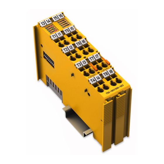
WAGO-I/O-SYSTEM 750 Device Description 750-667/000-003 4FDI/4FDO 24V/2A PROFIsafe V2 iPar View Figure 4: View Table 4: Legend for Figure “View” Pos. Description Details See Section Marking possibility with Mini- Status LEDs “Device Description” > “Display Elements” Data contacts “Device Description” > “Connectors”... -
Page 22: Connectors
Device Description WAGO-I/O-SYSTEM 750 750-667/000-003 4FDI/4FDO 24V/2A PROFIsafe V2 iPar Connectors 4.2.1 Data Contacts/Local Bus Communication between the fieldbus coupler/controller and the I/O modules as well as the system supply of the I/O modules is carried out via the local bus. It is comprised of 6 data contacts, which are available as self-cleaning gold spring contacts. -
Page 23: Power Jumper Contacts/Field Supply
WAGO-I/O-SYSTEM 750 Device Description 750-667/000-003 4FDI/4FDO 24V/2A PROFIsafe V2 iPar 4.2.2 Power Jumper Contacts/Field Supply Risk of injury due to sharp-edged blade contacts! The blade contacts are sharp-edged. Handle the I/O module carefully to prevent injury. Do not touch the blade contacts. - Page 24 Device Description WAGO-I/O-SYSTEM 750 750-667/000-003 4FDI/4FDO 24V/2A PROFIsafe V2 iPar Use supply modules for ground (earth)! The I/O module has no power jumper contacts for receiving and transmitting the earth potential. Use a supply module when an earth potential is needed for the subsequent I/O modules.
-
Page 25: Cage Clamp ® Connectors
WAGO-I/O-SYSTEM 750 Device Description 750-667/000-003 4FDI/4FDO 24V/2A PROFIsafe V2 iPar ® 4.2.3 CAGE CLAMP Connectors ® Figure 7: CAGE CLAMP Connectors ® Table 6: Legend for Figure “CAGE CLAMP Connectors” Channel Designation Connector Function Clock output T1 Input I1: Clock output... -
Page 26: Display Elements
Device Description WAGO-I/O-SYSTEM 750 750-667/000-003 4FDI/4FDO 24V/2A PROFIsafe V2 iPar Display Elements Figure 8: Display Elements, Inputs 1 ... 4 Table 7: Legend for Figure “Display Elements, Inputs 1 ... 4” Channel Designation Status Function Input I1: Signal voltage (0) -
Page 27: Figure 9: Display Elements, Outputs 1
WAGO-I/O-SYSTEM 750 Device Description 750-667/000-003 4FDI/4FDO 24V/2A PROFIsafe V2 iPar Figure 9: Display Elements, Outputs 1 ... 4 Table 8: Legend for Figure “Display Elements, Outputs 1 ... 4” Channel Designation Status Function Output O1: Signal voltage (0) Status Green... -
Page 28: Figure 10: Display Elements, Communication/ I/O Module Status
No valid PROFIsafe F parameters available Red 1 Hz Watchdog time (F_WD_Time) exceeded flashing Parameterization OK F I/O module selected by WAGO-I/O- CHECK Red 1 Hz Parameter Individual parameter invalid flashing Setting Red 2 Hz Configuration running and not yet... - Page 29 If the problem occurs several times, it points to a defect in the F I/O module. In this case, return the F I/O module to WAGO Kontakttechnik GmbH & Co. KG for fault analysis.
-
Page 30: Operating Elements
Device Description WAGO-I/O-SYSTEM 750 750-667/000-003 4FDI/4FDO 24V/2A PROFIsafe V2 iPar Operating Elements You can use the coding switch located on the side of the F I/O module to set the PROFIsafe address. Figure 11: Coding Switch for the PROFIsafe Address (set to 1018) -
Page 31: Schematic Diagrams
WAGO-I/O-SYSTEM 750 Device Description 750-667/000-003 4FDI/4FDO 24V/2A PROFIsafe V2 iPar Schematic Diagrams Figure 12: Schematic Diagram 4.5.1 Input Block Diagram Figure 13: Input Block Diagram Manual Version 1.4.2, valid from HW/SW Version 01/02... -
Page 32: Output Block Diagram
Device Description WAGO-I/O-SYSTEM 750 750-667/000-003 4FDI/4FDO 24V/2A PROFIsafe V2 iPar 4.5.2 Output Block Diagram Figure 14: Output Block Diagram Manual Version 1.4.2, valid from HW/SW Version 01/02... -
Page 33: Technical Data
WAGO-I/O-SYSTEM 750 Device Description 750-667/000-003 4FDI/4FDO 24V/2A PROFIsafe V2 iPar Technical Data 4.6.1 Device Data Table 10: Technical Data — Device Width 24 mm Height (from upper edge of DIN-35 rail) 64 mm Depth 100 mm Weight Approx. 100 g 4.6.2... -
Page 34: Communication
Device Description WAGO-I/O-SYSTEM 750 750-667/000-003 4FDI/4FDO 24V/2A PROFIsafe V2 iPar 4.6.3 Communication Table 12: Technical Data ‒ Communication 750-333 SW 14, HW 16 or higher 750-370 SW 02, HW 01 or higher Usable fieldbus couplers / controllers 750-375 SW 02, HW 01 or higher... -
Page 35: Digital Inputs
WAGO-I/O-SYSTEM 750 Device Description 750-667/000-003 4FDI/4FDO 24V/2A PROFIsafe V2 iPar 4.6.4 Digital Inputs Table 13: Technical Data ‒ Digital Inputs Inputs I1 … I4 4 inputs type 1 acc. EN 61131-2 4 × Cat. 2/PL d acc. EN ISO 13849-1 2 ×... -
Page 36: Digital Power Outputs
Device Description WAGO-I/O-SYSTEM 750 750-667/000-003 4FDI/4FDO 24V/2A PROFIsafe V2 iPar Table 15: Technical Data ‒ Clock Pulse Duration at Input Filter Time Input filter time 0 ms Clock pulse duration 5 ms Input filter time 0.5 ms Clock pulse duration 5 ms... - Page 37 WAGO-I/O-SYSTEM 750 Device Description 750-667/000-003 4FDI/4FDO 24V/2A PROFIsafe V2 iPar Table 16: Technical Data ‒ Digital Power Outputs Min. 66 μA Response threshold line break detection Max. 130 μA Parallel connection of outputs Not possible See section “Connection Examples” Controlling outputs >...
-
Page 38: Safety Parameters
Device Description WAGO-I/O-SYSTEM 750 750-667/000-003 4FDI/4FDO 24V/2A PROFIsafe V2 iPar 4.6.7 Safety Parameters 4.6.7.1 Two-channel Safety Application, Proof Test Interval 10 Years Table 17: Safety Parameters for 2-Channel Safety Applications – 10 Years Maximum safety integrity level SIL3 acc. EN 62061... -
Page 39: Two-Channel Safety Application, Proof Test Interval 20 Years
WAGO-I/O-SYSTEM 750 Device Description 750-667/000-003 4FDI/4FDO 24V/2A PROFIsafe V2 iPar 4.6.7.2 Two-channel Safety Application, Proof Test Interval 20 Years Table 18: Safety Parameters for 2-Channel Safety Applications – 20 Years Maximum safety integrity level SIL3 acc. EN 62061 Maximum safety integrity level SIL3 acc. -
Page 40: Single-Channel Safety Application, Proof Test Interval 10 Years
Device Description WAGO-I/O-SYSTEM 750 750-667/000-003 4FDI/4FDO 24V/2A PROFIsafe V2 iPar 4.6.7.3 Single-channel Safety Application, Proof Test Interval 10 Years Table 19: Safety Parameters for Single-Channel Safety Application – 10 Years Maximum safety integrity level SIL2 acc. EN 62061 Maximum safety integrity level SIL2 acc. -
Page 41: Single-Channel Safety Application, Proof Test Interval 20 Years
WAGO-I/O-SYSTEM 750 Device Description 750-667/000-003 4FDI/4FDO 24V/2A PROFIsafe V2 iPar 4.6.7.4 Single-channel Safety Application, Proof Test Interval 20 Years Table 20: Safety Parameters for Single-Channel Safety Application – 20 Years Maximum safety integrity level SIL2 acc. EN 62061 Maximum safety integrity level SIL2 acc. -
Page 42: Connection Type
Device Description WAGO-I/O-SYSTEM 750 750-667/000-003 4FDI/4FDO 24V/2A PROFIsafe V2 iPar 4.6.8 Connection Type Table 21: Technical Data – Field Wiring ® Wire connection CAGE CLAMP Cross section 0.08 mm² … 2.5 mm², AWG 28 … 14 Stripped lengths 8 mm … 9 mm / 0.33 in Table 22: Technical Data –... -
Page 43: Response Times
Configuring the F I/O module is described in the section "Parameteriziation of the F I/O module with the WAGO Parameterization Tool". Manual Version 1.4.2, valid from HW/SW Version 01/02... -
Page 44: Table 25: Safe Response Time Of The Digital Inputs In The Event Of Failure
Device Description WAGO-I/O-SYSTEM 750 750-667/000-003 4FDI/4FDO 24V/2A PROFIsafe V2 iPar The following table lists the safe response times in the event of failure that result from the input filter time set. Table 25: Safe Response Time of the Digital Inputs in the Event of Failure... -
Page 45: Typical Response Time Of The Digital Inputs In An Error-Free Case
WAGO-I/O-SYSTEM 750 Device Description 750-667/000-003 4FDI/4FDO 24V/2A PROFIsafe V2 iPar 4.6.10.2 Typical Response Time of the Digital Inputs in an Error-free Case Only use response times in the event of a failure for the safety response time! To prevent any personal injury or property damage, only use the values of the safe response time for errors for defining the safety response time (see Section "Safe Response Time of Digital Inputs in the Event of a Failure"). -
Page 46: Safe Response Time Of Digital Power Outputs
The safe response time of the digital power outputs depends on the protective circuit used and the test pulse length configured. You can set the Test pulse parameter in stages using the WAGO parameterization tool. For more information, read the section “Parameterization of the F I/O module with the WAGO Parameterization Tool”. -
Page 47: Response Time Of The Digital Power Outputs For A Load Between Ox+ And Ox− In The Event Of Failure
WAGO-I/O-SYSTEM 750 Device Description 750-667/000-003 4FDI/4FDO 24V/2A PROFIsafe V2 iPar 4.6.10.4 Response Time of the Digital Power Outputs for a Load between Ox+ and Ox− in the Event of Failure For the safety response time, take into account the execution times of the... -
Page 48: Response Time Of The Digital Power Outputs For A Load Between Ox+ And 0 V In The Event Of Failure
Device Description WAGO-I/O-SYSTEM 750 750-667/000-003 4FDI/4FDO 24V/2A PROFIsafe V2 iPar 4.6.10.5 Response Time of the Digital Power Outputs for a Load between Ox+ and 0 V in the Event of Failure For the safety response time, take into account the execution times of the... -
Page 49: Response Time Of The Digital Power Outputs For A Load Between 24 V And Ox
WAGO-I/O-SYSTEM 750 Device Description 750-667/000-003 4FDI/4FDO 24V/2A PROFIsafe V2 iPar 4.6.10.6 Response Time of the Digital Power Outputs for a Load between 24 V and Ox− For the safety response time, take into account the execution times of the local bus, fieldbus and cycle time of the safe PLC! -
Page 50: Response Time Of The Digital Power Outputs For A Load Between Ox+ And 0 V, As Well As 24 V And Ox
Device Description WAGO-I/O-SYSTEM 750 750-667/000-003 4FDI/4FDO 24V/2A PROFIsafe V2 iPar 4.6.10.7 Response Time of the Digital Power Outputs for a Load between Ox+ and 0 V, as well as 24 V and Ox− For the safety response time, take into account the execution times of the... -
Page 51: Approvals
Approvals More information about approvals. Detailed references to the approvals are listed in the document “Overview Approvals WAGO-I/O-SYSTEM 750”, which you can find via the internet under: www.wago.com DOWNLOADS Documentation System Description. The following approvals have been granted to 750-667/000-003 F I/O modules:... - Page 52 Device Description WAGO-I/O-SYSTEM 750 750-667/000-003 4FDI/4FDO 24V/2A PROFIsafe V2 iPar Federal Maritime and Hydrographic Agency GL (Germanischer Lloyd) Cat. A, B, C, D (EMC 2) Manual Version 1.4.2, valid from HW/SW Version 01/02...
-
Page 53: Standards And Guidelines
WAGO-I/O-SYSTEM 750 Device Description 750-667/000-003 4FDI/4FDO 24V/2A PROFIsafe V2 iPar Standards and Guidelines 750-667/000-003 F I/O modules meet the following requirements on safety: Safety of machinery IEC 61508, parts 1-7 Functional safety of electrical/ electronic/ programmable electronic safety-related systems Safety of machinery –... -
Page 54: Transport And Storage Conditions
Device Description WAGO-I/O-SYSTEM 750 750-667/000-003 4FDI/4FDO 24V/2A PROFIsafe V2 iPar 4.8.1 Transport and Storage Conditions During transport and storage, the F I/O modules must be protected against undue stress such as mechanical loads, temperature, humidity and aggressive atmospheres. The F I/O modules should be stored in the original packaging when possible, which offers optimal protection during transport. -
Page 55: Process Image
WAGO-I/O-SYSTEM 750 Process Image 750-667/000-003 4FDI/4FDO 24V/2A PROFIsafe V2 iPar Process Image The F I/O module 750-667/000-003 occupies five data bytes in the input and output process image in the higher-level secure PLC. The secure PROFIsafe telegrams to send and receive are stored in input and output bytes 0 … 4. -
Page 56: Profisafe V2 Mode
Process Image WAGO-I/O-SYSTEM 750 750-667/000-003 4FDI/4FDO 24V/2A PROFIsafe V2 iPar PROFIsafe V2 Mode Table 34: Process Image PROFIsafe V2 Mode Input data Output data Byte 0 Inputs Byte 0 Outputs Byte 1 Status byte Byte 1 Control byte Byte 2... -
Page 57: Mounting
Don't forget the bus end module! Always plug a bus end module (750-600) onto the end of the fieldbus node! You must always use a bus end module at all fieldbus nodes with WAGO-I/O- SYSTEM 750 fieldbus couplers or controllers to guarantee proper data transfer. -
Page 58: Inserting And Removing Devices
Mounting WAGO-I/O-SYSTEM 750 750-667/000-003 4FDI/4FDO 24V/2A PROFIsafe V2 iPar Inserting and Removing Devices Do not work when devices are energized! High voltage can cause electric shock or burns. Switch off all power to the device prior to performing any installation, repair or maintenance work. -
Page 59: Removing The I/O Module
WAGO-I/O-SYSTEM 750 Mounting 750-667/000-003 4FDI/4FDO 24V/2A PROFIsafe V2 iPar 6.2.2 Removing the I/O Module Remove the I/O module from the assembly by pulling the release tab. Figure 21: Removing the I/O Module (Example) Electrical connections for data or power jumper contacts are disconnected when removing the I/O module. -
Page 60: Connect Devices
Only one conductor may be connected to each CAGE CLAMP Do not connect more than one conductor at one single connection! If more than one conductor must be routed to one connection, these must be connected in an up-circuit wiring assembly, for example using WAGO feed- through terminals. ®... -
Page 61: Power Supply Concept
WAGO-I/O-SYSTEM 750 Connect Devices 750-667/000-003 4FDI/4FDO 24V/2A PROFIsafe V2 iPar Power Supply Concept The F I/O module receives the field supply voltage via the power jumper contacts listed as knife blade contacts from an upstream I/O module, the fieldbus coupler/controller or an internal system power supply and makes this potential available via the power jumper contacts listed as spring contacts for downstream I/O modules. -
Page 62: Figure 23: Infeed For F I/O Modules 750-66X And 753-66X
Connect Devices WAGO-I/O-SYSTEM 750 750-667/000-003 4FDI/4FDO 24V/2A PROFIsafe V2 iPar Figure 23: Infeed for F I/O Modules 750-66x and 753-66x Do not exceed maximum current via power contacts! The maximum current that can flow through the power jumper contacts is 10 A. -
Page 63: Using A Backup Capaciter In Case Of Interruptions In The Power Supply
To this effect, you can use a backup capacitor module for the WAGO-I/O-SYSTEM 750 with a capacity of 10000 μF (item No. 288-824). The back-up capacitor module (item No. -
Page 64: Using 230 Vac I/O Modules
Connect Devices WAGO-I/O-SYSTEM 750 750-667/000-003 4FDI/4FDO 24V/2A PROFIsafe V2 iPar 7.2.2 Using 230 VAC I/O Modules If 230 VAC I/O modules are used together with F I/O modules in one fieldbus node, there are two options: 7.2.2.1 230 VAC Modules are Used in Another Fieldbus Node that Contains... -
Page 65: Connection Examples
F I/O module for implementation of a safety function are used. For the digital inputs of the F I/O module, you can use the WAGO parameterization tool during individual parameterization to select the "Standard"... -
Page 66: Figure 25: Connection 4 X Emergency-Off, Single-Channel, Short-Circuit
Connect Devices WAGO-I/O-SYSTEM 750 750-667/000-003 4FDI/4FDO 24V/2A PROFIsafe V2 iPar Pay attention to the protected installation of signal lines during short circuit test "inactive"! If you have set the Short circuit test parameter of an input to "inactive", the signal lines must be installed protected among each other and between the sensors and inputs according to EN 60204-1 or EN ISO 13849-2 (e.g., as... -
Page 67: Emergency Off Connection, Dual Channel, Equivalent Evaluation
Dual channel evaluation parameter to “no”. For more information about configuring the F I/O module, read section “Commissioning” > … > “Parameterization of the F I/O modules with the WAGO Parameterization Tool”. If you do not connect the digital input via a switching element to the associated clock output (e.g., semiconductor output), set the Short circuit test parameter to... -
Page 68: Figure 27: Connection 2 X Emergency-Off Switch, Dual Channel, Equivalent
(two-channel emergency off switches with two break contacts) to the F I/O module. Use the WAGO parameterization tool to set the parameters. For more information about configuring the F I/O module, read section "Parameterization of the F I/O module with the WAGO Parameterization Tool". -
Page 69: Protective Door Monitoring Connection, Dual Channel, Antivalent Evaluation
F I/O module. For more information about configuring the F I/O module, read section "Parameterization of the F I/O module with the WAGO Parameterization Tool". Set the Dual channel evaluation parameter for the digital inputs used to "yes". -
Page 70: Connection Example For Digital Inputs In Rotary Table Operating Mode (1 Of N)
Figure 29: Connection 1 x Mode Selector Switch If you have set the Operating mode parameter to "Rotary table" using the WAGO parameterization tool, you can connect the normally open contacts of a mode selector switch or several rotary table sensors to the digital inputs of the F I/O module. -
Page 71: Connection Examples For Digital Power Outputs
A suitable module must be used in the safety application of the safe PLC to analyze the input bits. Note Use application notes from WAGO! An overview for using F I/O module in combination with a safe PLC is summarized in an application note. This application note is available on the Internet at www.wago.com... -
Page 72: Switching Inductive Loads
Connect Devices WAGO-I/O-SYSTEM 750 750-667/000-003 4FDI/4FDO 24V/2A PROFIsafe V2 iPar 7.3.3.2 Switching Inductive Loads Defect by thermal overheating if the switching frequency is too high! If the inductivity and load current you have selected is too high for the selected switching frequency, it can lead to thermal destruction of the digital power output. - Page 73 WAGO-I/O-SYSTEM 750 Connect Devices 750-667/000-003 4FDI/4FDO 24V/2A PROFIsafe V2 iPar Figure 3: Connection Variant with Diode Recovery Circuit When shutting down an inductive load, the magnetic energy stored in the inductive load must be dissipated. This magnetic energy converted by a diode recovery circuit into heat.
-
Page 74: Switching Electronic Loads
"active" so that the F I/O module performs the open load detection task once per minute. For more information about configuring the F I/O module, read section "Parameterization of the F I/O module with the WAGO Parameterization Tool". Manual Version 1.4.2, valid from HW/SW Version 01/02... -
Page 75: Connecting Loads From Ox+ And Ox− To 0 V And 24 V
WAGO-I/O-SYSTEM 750 Connect Devices 750-667/000-003 4FDI/4FDO 24V/2A PROFIsafe V2 iPar Open load detection on the digital outputs To monitor line interruptions between the digital power outputs Ox+ or Ox− and the connected load, you can set the line break detection parameter for each digital power output separately. -
Page 76: Connecting Two Parallel Loads To A Digital Power Output
For more information about configuring the F I/O module, read section "Parameterization of the F I/O module with the WAGO Parameterization Tool". With this connection, you can achieve SIL3/Cat. 4/PL e by re-reading the relay states. -
Page 77: Connecting Loads Between Ox+ To The Ground Connection 0 V
WAGO-I/O-SYSTEM 750 Connect Devices 750-667/000-003 4FDI/4FDO 24V/2A PROFIsafe V2 iPar Open load detection for supply lines to the loads only! If you connect two loads parallel to a digital power output (as depicted in the figure), the F I/O module only detects open loads on the supply lines. -
Page 78: Connecting The Digital Power Outputs To Digital Inputs
Also observe the minimum load of the digital power output. For more information about configuring the F I/O module, read section "Parameterization of the F I/O module with the WAGO Parameterization Tool". Manual Version 1.4.2, valid from HW/SW Version 01/02... -
Page 79: Motor Connection, Single-Channel With Feedback (1 Contactor Per Motor)
WAGO-I/O-SYSTEM 750 Connect Devices 750-667/000-003 4FDI/4FDO 24V/2A PROFIsafe V2 iPar Open load detection not possible! When connecting a digital power output to a digital input directly, open load detection is not possible for this power output Ox+. Set the Open load detection parameter to "not active"... -
Page 80: Connecting 2 Motors, Two-Channel With Feedback (2 Actors Per Motor)
For more information about configuring the F I/O module, read section "Parameterization of the F I/O module with the WAGO Parameterization Tool". Please note that open load detection may not be part of the safety function under any circumstances. - Page 81 For more information about configuring the F I/O module, read section "Parameterization of the F I/O module with the WAGO Parameterization Tool". Please note that open load detection may not be part of the safety function under any circumstances.
-
Page 82: Connecting 4 Dc Motors
For more information about configuring the F I/O module, read section “Commissioning” > … > “Parameterization of the F I/O modules with the WAGO Parameterization Tool”. Please note that open load detection may not be part of the safety function under any circumstances. -
Page 83: Commissioning
The serial number consists of the week and year of manufacture, software version (if available), hardware version, firmware loader version (if available) and other internal information from WAGO Kontakttechnik GmbH & Co. KG. Manual Version 1.4.2, valid from HW/SW Version 01/02... -
Page 84: Adding Or Replacing Components
The PROFIsafe address set on the coding switch of the I/O module has priority over the PROFIsafe address set by the WAGO parameterization tool. Only when the address set on the coding switch equals 0 does the setting of the PROFIsafe address using the WAGO parameterization tool take effect. -
Page 85: Setting The Profisafe Address Using The Wago Parameterization Tool
To configure the PROFIsafe address through storage in the parameter data set of the I/O module, set the PROFIsafe address in the WAGO parameterization tool to the required value and save the current parameter data set to the I/O module. -
Page 86: Online Mode
“Commissioning” > … > ”F I/O Module with iPar Functionality without iPar Server”). The 75x 2.x WAGO Safety Editor can be started with various call versions. Depending on the call option, the Safety Editor is started in either ONLINE or OFFLINE mode. - Page 87 Confirm your entries by clicking [OK]. Then the Save WAGO safety parameter set dialog opens. Enter a name for the parameter file and select the directory in which the file is to be saved. Then click on [Save] in order save the file to the hard disk.
-
Page 88: Offline Mode
I/O module and the language support. In the Open WAGO Safety Parameter Set dialog, enter the name of the parameter file that should be loaded. Then click on the [Open] button to load the selected file. - Page 89 Confirm your entries by clicking [OK]. Then the Save WAGO safety parameter set dialog opens. Enter a name for the parameter file and select the directory in which the file is to be saved. Then click on [Save] in order save the file to the hard disk.
-
Page 90: Description Of The Call Options
8.3.3 Description of the Call Options The WAGO Safety Editor can be started with various call versions. Depending on the call option, the Safety Editor is started in either ONLINE or OFFLINE mode. In ONLINE mode, different communication media are available (serial... -
Page 91: Indirect Start Via Wago-I/O-Check From The Configuration Program (Device Level Tci Conformance Class 2)
(Device Level TCI Conformance Class 2) In the configuration program of the safe PLC, select a device (fieldbus coupler) and launch “WAGO-I/O-CHECK 3” from the TCI link. The configuration program passes the current language and communication setting to WAGO-I/O-CHECK. Select an F I/O module for parameterization from the fieldbus node configuration displayed in WAGO-I/O-CHECK. -
Page 92: Direct Start From The Configuration Program (Device Level Tci Conformance Class 3 Offline)
Conformance Class 3 OFFLINE) n the configuration program of the safe PLC, select a device (fieldbus coupler) and from the TCI link “WAGO-Safety-Editor 75x” (offline), start the WAGO- Safety-Editor 75x. The configuration program passes the current language setting to the Safety Editor. The Safety Editor is started in OFFLINE mode. -
Page 93: Adjustable Parameters
WAGO-I/O-SYSTEM 750 Commissioning 750-667/000-003 4FDI/4FDO 24V/2A PROFIsafe V2 iPar 8.3.4 Adjustable Parameters Table 37: Adjustable Parameters Parameter Value Range 0 (off) / 0.2 / 0.5 / 1 / 2 / 3* / 5 / 10 / 20 / 50 / 100 /... -
Page 94: Parameter Input Filter Time
Commissioning WAGO-I/O-SYSTEM 750 750-667/000-003 4FDI/4FDO 24V/2A PROFIsafe V2 iPar 8.3.4.1 Parameter Input Filter Time Configuring the input filter time changes the safe response time! If you change the Input Filter Time parameter, then the safe response time is also changed. See "Response Time" section. -
Page 95: Parameter Short-Circuit Test Ix
WAGO-I/O-SYSTEM 750 Commissioning 750-667/000-003 4FDI/4FDO 24V/2A PROFIsafe V2 iPar 8.3.4.2 Parameter Short-Circuit Test Ix Protect signal lines when installing! When connecting signal lines to the digital inputs of the F I/O module, make sure that only the following signals are transmitted within a cable or non-metallic sheathed cable: •... -
Page 96: Table 40: Error Detection
Commissioning WAGO-I/O-SYSTEM 750 750-667/000-003 4FDI/4FDO 24V/2A PROFIsafe V2 iPar Table 40: Error Detection Error Detection Error, Example Short-Circuit Test Short-Circuit Test (x = 1 ... 4, m = 1.2) "Active" "Not Active" Short circuit I1 / I2 Short circuit I3 / I4... -
Page 97: Parameter Two-Channel Analysis Ix & Ix+1
I/O module and makes automatic corrections if necessary by setting the value to “active” for both digital inputs. The automatic correction is displayed in the WAGO parameterization tool. You can set the values of both digital inputs to the same value after the correction is made. -
Page 98: Discrepancy Time Ix & Ix+1 Parameter
Commissioning WAGO-I/O-SYSTEM 750 750-667/000-003 4FDI/4FDO 24V/2A PROFIsafe V2 iPar 8.3.4.4 Discrepancy Time Ix & Ix+1 Parameter Do not use discrepancy time monitoring as part of the safety function! You can only use discrepancy monitoring for safety applications where monitoring of both contacts does not represent its own safety function such as... - Page 99 WAGO-I/O-SYSTEM 750 Commissioning 750-667/000-003 4FDI/4FDO 24V/2A PROFIsafe V2 iPar • No equivalent (same) states are detected with equivalent valence rule • No antivalent (opposing) states are detected with antivalent valence rule Activate discrepancy time monitoring only after the set input filter time has elapsed! Discrepancy time monitoring is only activated if the input filter time has expired.
-
Page 100: Parameter Valence Evaluation Ix & Ix+1
100 Commissioning WAGO-I/O-SYSTEM 750 750-667/000-003 4FDI/4FDO 24V/2A PROFIsafe V2 iPar 8.3.4.5 Parameter Valence Evaluation Ix & Ix+1 The Valence evaluation parameter is used for the dual channel evaluation of two digital inputs Ix & Ix+1. The valence evaluation is then only used by the F I/O module if you have set the value of the Operating mode parameter to "Standard"... -
Page 101: Parameter Restart Inhibit Ix & Ix+1
WAGO-I/O-SYSTEM 750 Commissioning 101 750-667/000-003 4FDI/4FDO 24V/2A PROFIsafe V2 iPar The F I/O module compares the signal states of the digital inputs affected to the same values. The following table shows the possible signal states for the equivalent evaluation: Table 42: Equivalent Evaluation... -
Page 102: Operating Mode Parameter
102 Commissioning WAGO-I/O-SYSTEM 750 750-667/000-003 4FDI/4FDO 24V/2A PROFIsafe V2 iPar Table 43: Necessary Signal States for Acknowledgement if the Restart Inhibit is Set to "yes" Digital Inputs Input Pair Valence Evaluation "1" "0" "Antivalent" I1 & I2 "0" "0" "Equivalent"... -
Page 103: Parameter Open Load Detection
WAGO-I/O-SYSTEM 750 Commissioning 103 750-667/000-003 4FDI/4FDO 24V/2A PROFIsafe V2 iPar • The Short circuit test parameter is only accepted by the F I/O module with the "active" value. • All inputs are sensitive to clock output T1 and are tested for short circuit on any 24 V signal source. -
Page 104: Test Pulse Duration Parameter
104 Commissioning WAGO-I/O-SYSTEM 750 750-667/000-003 4FDI/4FDO 24V/2A PROFIsafe V2 iPar </dg_ 8.3.4.9 Test Pulse Duration Parameter No test pulses when test pulse duration = 0 ms! If you have set the test pulse duration of a digital power output (1 or 2-channel) to the value “0 ms (off)”, the F I/O module does not perform a cyclic diagnostic test... - Page 105 WAGO-I/O-SYSTEM 750 Commissioning 105 750-667/000-003 4FDI/4FDO 24V/2A PROFIsafe V2 iPar Internal test pulse also when test pulse duration = 0 ms! (applies to SW version 06) Please note that the F I/O module up to software version 06 also performs an internal test pulse expressed by briefly switching off all digital power outputs when the test pulse duration is set to 0 ms.
-
Page 106: Programming The Safe Plc
• Use of a suitable programming and configuration environment • Selection of a WAGO fieldbus coupler (PROFIBUS, PROFINET) • Use of the current WAGO device description file (GSD, GSDML) After selecting a suitable safe PLC, add the required bus system (PROFIBUS or PROFINET) to the hardware configuration environment and configure it accordingly (fieldbus parameters, addresses, names, etc.). -
Page 107: F I/O Module Without Ipar Functionality
Then recompile the configuration and transfer it so the safe PLC. Then configure the F I/O module using the WAGO parameterization tool as described in the section “Start Up” > … > “Parameterization of the F I/O module with the WAGO Parameterization Tool”. -
Page 108: F I/O Module With Ipar Functionality Without Ipar Server
Then configure the F I/O module using the WAGO parameterization tool (see the section “Start Up” > … > "Parameterization of the F I/O module with the WAGO Parameterization Tool"). The WAGO parameterization tool displays the iPar_CRC. - Page 109 “Error when downloading individual parameters” diagnostic message first appears after about 4.5 minutes. As a remedy, adjust the individual parameters of the F I/O module using the WAGO parameterization tool. Observe the required workflows listed in the respective manufacturer's documentation and check and document all safety functions.
-
Page 110: Diagnostics
If shutdowns occur frequently due to internal errors, the F I/O module should be replaced. In this case, return the defective F I/O module to WAGO Kontakttechnik GmbH & Co. KG for fault analysis. Manual Version 1.4.2, valid from HW/SW Version 01/02... -
Page 111: Diagnosis Of Errors
The structure of the diagnostic messages is described in the fieldbus coupler manuals. The PROFIsafe I/O module 750-667/000-003 can be operated on the WAGO-I/O-SYSTEM 750 fieldbus couplers specified in section “Technical Data” > … > “Communication”: Manual Version 1.4.2, valid from HW/SW Version 01/02... -
Page 112: Table 44: Diagnostic Messages
112 Diagnostics WAGO-I/O-SYSTEM 750 750-667/000-003 4FDI/4FDO 24V/2A PROFIsafe V2 iPar Table 44: Diagnostic Messages Alarm Description Diagnostic Module diagnostics type Coding 0x0040 Group error (E) red Differing indication: PROFIsafe (G) red F_Dest_Add The PROFIsafe address assigned as part of the F parameterization differs from that Remedy set on the F I/O module.. - Page 113 The internal hardware test of the F I/O module failed or the operating program is no longer running properly. Immediately Remedy replace the F I/O module and return it to WAGO Kontakttechnik GmbH & Co. KG for fault analysis. Diagnostic Channel diagnostics type...
- Page 114 114 Diagnostics WAGO-I/O-SYSTEM 750 750-667/000-003 4FDI/4FDO 24V/2A PROFIsafe V2 iPar Table 44: Diagnostic Messages Alarm Description Diagnostic Module diagnostics type Coding 0x020B Short circuit on T1 Group error (E) red indication: Clock output T1 of the F I/O module has...
- Page 115 The F I/O module has taken the safe state and switched off the outputs. Immediately Remedy replace the F I/O module and return it to WAGO Kontakttechnik GmbH & Co. KG for fault analysis. Diagnostic Channel diagnostics type Coding...
- Page 116 116 Diagnostics WAGO-I/O-SYSTEM 750 750-667/000-003 4FDI/4FDO 24V/2A PROFIsafe V2 iPar Table 44: Diagnostic Messages Alarm Description Diagnostic Module diagnostics type Coding 0x0205 Group error (E) red indication: Over temperature The permissible operating temperature of the semiconductor in the F I/O module has Remedy been exceeded.
- Page 117 WAGO-I/O-SYSTEM 750 Diagnostics 117 750-667/000-003 4FDI/4FDO 24V/2A PROFIsafe V2 iPar Table 44: Diagnostic Messages Alarm Description Diagnostic Module diagnostics type Coding 0x0041 Invalid Group error (E) red F_Dest_Add indication: The PROFIsafe address of the F I/O Remedy module must lie within the range of 1 to 65534.
-
Page 118: Acknowledging Error Messages
118 Diagnostics WAGO-I/O-SYSTEM 750 750-667/000-003 4FDI/4FDO 24V/2A PROFIsafe V2 iPar Acknowledging Error Messages When detecting an error, a message is sent by the PROFIBUS I/O module to the safe PLC. More information about error detection by the F I/O module is available in the section “Diagnosis”... -
Page 119: Variant 1: User Acknowledgement Via "Oa_Req
WAGO-I/O-SYSTEM 750 Diagnostics 119 750-667/000-003 4FDI/4FDO 24V/2A PROFIsafe V2 iPar Variant 1: User Acknowledgement via “OA_Req” 9.3.1 For safe PLCs that offer access to the “OA_Req” bit in the PROFIsafe control byte, the “OA_Req” bit can be used by the safe PLC. The acknowledgement request from the error is signaled by the PROFIsafe status display element to the F I/O module. -
Page 120: Variant 2: User Acknowledgement Via "Oa_Req" And "F_Ack
120 Diagnostics WAGO-I/O-SYSTEM 750 750-667/000-003 4FDI/4FDO 24V/2A PROFIsafe V2 iPar 9.3.2 Variant 2: User Acknowledgement via “OA_Req” and “F_Ack” For safe PLCs that offer the safe application no access to the “OA_Req”, only PROFIsafe communication errors can be acknowledged via the “OA_Req” bit in the PROFIsafe control byte. -
Page 121: Service
WAGO-I/O-SYSTEM 750 Service 121 750-667/000-003 4FDI/4FDO 24V/2A PROFIsafe V2 iPar Service 10.1 Replacing an F I/O Module Replacing an F I/O module with an F I/O module of the same type is described below. Replacing an F I/O module with an I/O module of another type is always associated with a new project design (see section “Commissioning”... -
Page 122: I/O Module With Ipar Server Functionality
I/O module sends a second request to the iPar server. If the process cannot be completed successfully, the replacement I/O module remains in its initial state and must be configured using the WAGO parameterization tool (see section “Commissioning” > … > “Parameterization of the F I/O Module with the WAGO Parameterization Tool”). -
Page 123: Profisafe Address Set Using The Parameterization Tool
0, the PROFIsafe address of the replacement I/O module must be set using the parameterization tool (see section “Parameterization of the F I/O Module with the WAGO Parameterization Tool”). In addition to setting the PROFIsafe address, also configure the replacement I/O module using the WAGO parameterization tool (see section “Commissioning”... -
Page 124: Use In Hazardous Environments
WAGO-I/O-SYSTEM 750 750-667/000-003 4FDI/4FDO 24V/2A PROFIsafe V2 iPar Use in Hazardous Environments The WAGO-I/O-SYSTEM 750 (electrical equipment) is designed for use in Zone 2 hazardous areas and shall be used in accordance with the marking and installation regulations. The following sections include both the general identification of components (devices) and the installation regulations to be observed. -
Page 125: Marking Configuration Examples
WAGO-I/O-SYSTEM 750 Use in Hazardous Environments 125 750-667/000-003 4FDI/4FDO 24V/2A PROFIsafe V2 iPar 11.1 Marking Configuration Examples 11.1.1 Marking for Europe According to ATEX and IECEx Figure 39: Marking Example According to ATEX and IECEx Figure 40: Text Detail – Marking Example According to ATEX and IECEx Manual Version 1.4.2, valid from HW/SW Version 01/02... -
Page 126: Table 45: Description Of Marking Example According To Atex And Iecex
126 Use in Hazardous Environments WAGO-I/O-SYSTEM 750 750-667/000-003 4FDI/4FDO 24V/2A PROFIsafe V2 iPar Table 45: Description of Marking Example According to ATEX and IECEx Marking Description TUEV 07 ATEX 554086 X Approving authority resp. certificate numbers IECEx TUN 09.0001 X... -
Page 127: Figure 41: Marking Example For Approved Ex I I/O Module According To
WAGO-I/O-SYSTEM 750 Use in Hazardous Environments 127 750-667/000-003 4FDI/4FDO 24V/2A PROFIsafe V2 iPar Figure 41: Marking Example for Approved Ex i I/O Module According to ATEX and IECEx Figure 42: Text Detail – Marking Example for Approved Ex i I/O Module According to ATEX and... -
Page 128: Table 46: Description Of Marking Example For Approved Ex I I/O Module According To Atex And Iecex
128 Use in Hazardous Environments WAGO-I/O-SYSTEM 750 750-667/000-003 4FDI/4FDO 24V/2A PROFIsafe V2 iPar Table 46: Description of Marking Example for Approved Ex i I/O Module According to ATEX and IECEx Marking Description TUEV 12 ATEX 106032 X Approving authority resp. certificate numbers... -
Page 129: Marking For The United States Of America (Nec) And Canada (Cec)
WAGO-I/O-SYSTEM 750 Use in Hazardous Environments 129 750-667/000-003 4FDI/4FDO 24V/2A PROFIsafe V2 iPar 11.1.2 Marking for the United States of America (NEC) and Canada (CEC) Figure 43: Marking Example According to NEC Figure 44: Text Detail – Marking Example According to NEC 500... -
Page 130: Figure 45: Text Detail - Marking Example For Approved Ex I I/O Module
130 Use in Hazardous Environments WAGO-I/O-SYSTEM 750 750-667/000-003 4FDI/4FDO 24V/2A PROFIsafe V2 iPar Figure 45: Text Detail – Marking Example for Approved Ex i I/O Module According to NEC 505 Table 48: Description of Marking Example for Approved Ex i I/O Module According to NEC 505... -
Page 131: Figure 47: Text Detail - Marking Example For Approved Ex I I/O Modules
WAGO-I/O-SYSTEM 750 Use in Hazardous Environments 131 750-667/000-003 4FDI/4FDO 24V/2A PROFIsafe V2 iPar Figure 47: Text Detail – Marking Example for Approved Ex i I/O Modules According to CEC 18 attachment J Table 50: Description of Marking Example for Approved Ex i I/O Modules According to CEC 18... -
Page 132: Installation Regulations
Special Notes Regarding Explosion Protection The following warning notices are to be posted in the immediately proximity of the WAGO-I/O-SYSTEM 750 (hereinafter “product”): WARNING – DO NOT REMOVE OR REPLACE FUSED WHILE ENERGIZED! WARNING – DO NOT DISCONNECT WHILE ENERGIZED! WARNING –... - Page 133 WAGO-I/O-SYSTEM 750 Use in Hazardous Environments 133 750-667/000-003 4FDI/4FDO 24V/2A PROFIsafe V2 iPar Explosive atmosphere occurring simultaneously with assembly, installation or repair work must be ruled out. Among other things, these include the following activities • Insertion and removal of components •...
-
Page 134: Special Notes Regarding Ansi/Isa Ex
134 Use in Hazardous Environments WAGO-I/O-SYSTEM 750 750-667/000-003 4FDI/4FDO 24V/2A PROFIsafe V2 iPar 11.2.2 Special Notes Regarding ANSI/ISA Ex For ANSI/ISA Ex acc. to UL File E198726, the following additional requirements apply: • Use in Class I, Division 2, Group A, B, C, D or non-hazardous areas only •... -
Page 135: Appendix
F-I/O-Module. F_SIL SIL3 The F-I/O-Module support SIL3. This value is specified by the WAGO device description file (GSD/GSDML). The F_CRC_Length parameter specifies the length of the CRC 2 key to be used in the PROFIsafe telegram. - Page 136 136 Appendix WAGO-I/O-SYSTEM 750 750-667/000-003 4FDI/4FDO 24V/2A PROFIsafe V2 iPar Table 51: PROFIsafe F Parameters F Parameters Default Value Description The F_Block_ID parameter specifies the format of the F parameter set. If F_Block_ID has the value “0”, the F_iPar_CRC parameter is not included in the F parameters and the iPar server is not used.
- Page 137 The monitoring time can be specified in steps of 1 ms. The possible value range (50 … 10000 ms) is specified by the WAGO device description file (GSD/GDML). The F_iPar_CRC is only available when F_Block_ID = 1 and specifies a comparison value for the CRC value via the individual Parameter (iPar_CRC).
-
Page 138: Profisafe Certificates
138 Appendix WAGO-I/O-SYSTEM 750 750-667/000-003 4FDI/4FDO 24V/2A PROFIsafe V2 iPar 12.2 PROFIsafe Certificates PROFIsafe Certificates A list of PROFIsafe certificates and PDFs of the certificates are available on the "AUTOMATION Tools and Docs" DVD-ROM (Art. No.: 0888-0412) or on the Internet at: http://www.wago.com. -
Page 139: Glossary
PLC. CPD Tool (Configuration Parametrization and Diagnosis Tool) The CPD tool can be used to parameterize configure and diagnose device functions of safe field devices (see also “WAGO Parameterization Tool” and “WAGO Safety Editor 75x 2.x”. CRC (Cyclic Redundancy Check) The cyclic redundancy check is a procedure for determining a test value for data to detect errors during transmission or storage. - Page 140 140 Glossary WAGO-I/O-SYSTEM 750 750-667/000-003 4FDI/4FDO 24V/2A PROFIsafe V2 iPar Dangerous Failure Termination of the capacity of a unit to complete the required function (see also “Failure”). DC (Diagnostic Coverage) The diagnostic coverage is the decrease in probability of dangerous hardware failures that result from executing automatic diagnostics tests.
- Page 141 Standardized mechanism for saving and restoring individual parameters (iPar) in the non-secure part of a control unit. Miniature WSB The miniature WSB marking accessories is a quick marking system (item No. 247-xxx) for WAGO connectors and I/O modules. MTTF (Mean Time To Failure Dangerous) The MTTF value specifies the mean time to a dangerous failure of a safe unit or sub-unit.
- Page 142 142 Glossary WAGO-I/O-SYSTEM 750 750-667/000-003 4FDI/4FDO 24V/2A PROFIsafe V2 iPar Overvoltage Category The overvoltage category is in indicator for the overvoltages, for example, that can occur at the place if installation due to lightening or switching operations. Passivate, passivation Passivation of safe digital inputs or power outputs is performed automatically by the F I/O module after activation or detection of errors.
- Page 143 WAGO-I/O-SYSTEM 750 Glossary 143 750-667/000-003 4FDI/4FDO 24V/2A PROFIsafe V2 iPar PROFIsafe V1 Mode acc. IEC 61784-3-3 PROFIsafe V1 Mode – Services and protocols of the safety-oriented PROFIsafe communication profile according to PROFIBUS Guideline: PROFIsafe – Profile for Safety Technology, V1.30, June 2004.
- Page 144 144 Glossary WAGO-I/O-SYSTEM 750 750-667/000-003 4FDI/4FDO 24V/2A PROFIsafe V2 iPar Safe PLC A safe PLC (Programmable Logic Controller) is a safety-oriented PLC that controls safe devices such as F I/O modules. Safety Function Function of a machine whose failure can lead to an immediate increase in the risk(s).
- Page 145 WAGO Safety Editor 75x 2.x The WAGO Safety Editor (SEDI) 75x 2.x is required together with the WAGO-I/O-CHECK 3.x to configure the F I/O module. SEDI is the CPD tool for WAGO F I/O modules (see also “CPD Tool (Configuration Parametrization and Diagnosis Tool)”).
-
Page 146: List Of Figures
146 List of Figures WAGO-I/O-SYSTEM 750 750-667/000-003 4FDI/4FDO 24V/2A PROFIsafe V2 iPar List of Figures Figure 1: Mixed Operation of Safety-Related and Non-Safety-Related I/O Modules ...................... 15 Figure 2: PROFIsafe Layer Model ............... 16 Figure 3: iPar Server .................... 17 Figure 4: View ...................... - Page 147 WAGO-I/O-SYSTEM 750 List of Figures 147 750-667/000-003 4FDI/4FDO 24V/2A PROFIsafe V2 iPar Figure 40: Text Detail – Marking Example According to ATEX and IECEx ..125 Figure 41: Marking Example for Approved Ex i I/O Module According to ATEX and IECEx ..................127 Figure 42: Text Detail –...
-
Page 148: List Of Tables
148 List of Tables WAGO-I/O-SYSTEM 750 750-667/000-003 4FDI/4FDO 24V/2A PROFIsafe V2 iPar List of Tables Table 1: Number Notation ..................9 Table 2: Font Conventions ..................9 Table 3: Legend for the iPar Server Figure ............18 Table 4: Legend for Figure “View” ............... 21 Table 5: Legend for Figure “Power Jumper Contacts”... - Page 149 WAGO-I/O-SYSTEM 750 List of Tables 149 750-667/000-003 4FDI/4FDO 24V/2A PROFIsafe V2 iPar Table 40: Error Detection ..................96 Table 41: Antivalent Evaluation ................. 100 Table 42: Equivalent Evaluation ................ 101 Table 43: Necessary Signal States for Acknowledgement if the Restart Inhibit is Set to "yes"...
- Page 150 WAGO Kontakttechnik GmbH & Co. KG Postfach 2880 • D - 32385 Minden Hansastraße 27 • D - 32423 Minden Phone: +49 571 887 – 0 Fax: +49 571 887 – 844169 E-Mail: info@wago.com Internet: www.wago.com...
Need help?
Do you have a question about the WAGO-I/O-SYSTEM 750 and is the answer not in the manual?
Questions and answers