WAGO -I/O-SYSTEM 750 Manual
4do 230 v ac 4-channel digital output 230 vac
Hide thumbs
Also See for WAGO-I/O-SYSTEM 750:
- User manual ,
- Manual (450 pages) ,
- User's installation and configuration (335 pages)
Table of Contents
Advertisement
Quick Links
WAGO-I/O-SYSTEM 750
Pos : 2 /D okumentati on allgemein/Ei nband/Ei nband H andbuch - Fronts eite 2015 - mit Doc Variabl en (Standar d) @ 9\mod_1285229289866_0.doc x @ 64941 @ @ 1
Manual
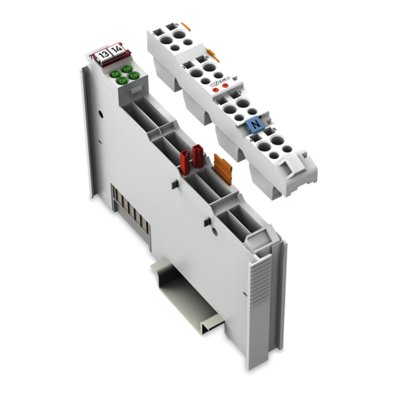
753-540
4DO 230 V AC
4-channel digital output 230 VAC
Version 1.1.0
Pos : 3 /Alle Serien (Allgemeine M odul e)/Rec htlic hes, Allgemei nes/Impressum für Standardhandbüc her - allg. Angaben, Ansc hriften, T elefonnummer n und E-Mail-Adres sen @ 3\mod_1219151118203_21.doc x @ 21060 @ @ 1
Advertisement
Chapters
Table of Contents


Need help?
Do you have a question about the WAGO-I/O-SYSTEM 750 and is the answer not in the manual?
Questions and answers