WAGO 750 Manual
4fdi 24v profisafe
Hide thumbs
Also See for 750:
- User manual ,
- Manual (450 pages) ,
- User's installation and configuration (335 pages)

Related Manuals for WAGO 750


Summary of Contents for WAGO 750
- Page 1 Manual WAGO I/O System 750 753-661/000-004 4FDI 24V PROFIsafe Safe 4-Channel Digital Input; 24 VDC; PROFIsafe Version 1.0.0, valid from HW/SW Version 01/01...
- Page 2 We wish to point out that the software and hardware terms as well as the trademarks of companies used and/or mentioned in the present manual are generally protected by trademark or patent. WAGO is a registered trademark of WAGO Verwaltungsgesellschaft mbH. Manual Version 1.0.0, valid from HW/SW Version 01/01...
-
Page 3: Table Of Contents
2.1.1 Subject to Changes ................10 2.1.2 Personnel Qualifications..............10 2.1.3 Use of the 750 Series in Compliance with Underlying Provisions ..10 2.1.4 Technical Condition of Specified Devices ......... 11 Safety Advice (Precautions) ..............12 Device Description ................... 16 View ....................... - Page 4 Setting the PROFIsafe Address using the Coding Switch ....53 7.2.2 Setting the PROFIsafe Address using the WAGO Parameterization Tool ............... 53 Parameterization of the F I/O Module with the WAGO Parameterization Tool ................54 7.3.1 ONLINE Mode ................... 55 7.3.1.1...
-
Page 5: Table Of Contents
Programming the Safe PLC ..............74 7.4.1 F I/O Module with iPar Server ............76 7.4.2 F I/O Module with iPar Functionality from WAGO ......76 7.4.3 F I/O Module without iPar Server ............76 Connection Examples ................77 7.5.1 Connection Examples for Digital Inputs .......... - Page 6 Table of Contents WAGO I/O System 750 753-661/000-004 4FDI 24V PROFIsafe Appendix ....................113 11.1 PROFIsafe ................... 113 11.1.1 Individual Parameters (iParameters) ..........115 11.2 Overview of PROFIsafe F Parameters ..........116 11.2.1 PROFIsafe Certificates..............119 Glossary ....................120 List of Figures ....................128 List of Tables ....................
-
Page 7: Notes About This Documentation
Consider power layout of the WAGO I/O System 750! In addition to these operating instructions, you will also need the manual for the used fieldbus coupler or controller, which can be downloaded at www.wago.com. There, you can obtain important information including information on electrical isolation, system power and supply specifications. -
Page 8: Symbols
Notes about this Documentation WAGO I/O System 750 753-661/000-004 4FDI 24V PROFIsafe Symbols Personal Injury! Indicates a high-risk, imminently hazardous situation which, if not avoided, will result in death or serious injury. Personal Injury Caused by Electric Current! Indicates a high-risk, imminently hazardous situation which, if not avoided, will result in death or serious injury. -
Page 9: Number Notation
WAGO I/O System 750 Notes about this Documentation 753-661/000-004 4FDI 24V PROFIsafe Additional Information: Refers to additional information which is not an integral part of this documentation (e.g., the Internet). Number Notation Table 1: Number Notation Number Code Example Note... -
Page 10: Important Notes
2.1.1 Subject to Changes WAGO GmbH & Co. KG reserves the right to provide for any alterations or modifications. WAGO GmbH & Co. KG owns all rights arising from the granting of patents or from the legal protection of utility patents. Third-party products are always mentioned without any reference to patent rights. -
Page 11: Technical Condition Of Specified Devices
These modules contain no parts that can be serviced or repaired by the user. The following actions will result in the exclusion of liability on the part of WAGO GmbH & Co. KG: •... -
Page 12: Safety Advice (Precautions)
Important Notes WAGO I/O System 750 753-661/000-004 4FDI 24V PROFIsafe Safety Advice (Precautions) For installing and operating purposes of the relevant device to your system the following safety precautions shall be observed: Do not work on devices while energized! All power sources to the device shall be switched off prior to performing any installation, repair or maintenance work. - Page 13 WAGO I/O System 750 Important Notes 753-661/000-004 4FDI 24V PROFIsafe Observe applicable standards! In a safety-related application, both the control as well as the attached sensors and actuators must meet the applicable normative safety requirements. Ensure that switches, sensors and actuators comply with current applicable standards before use.
- Page 14 Important Notes WAGO I/O System 750 753-661/000-004 4FDI 24V PROFIsafe Clean only with permitted materials! Clean housing and soiled contacts with propanol. Do not use any contact spray! Do not use any contact spray. The spray may impair contact area functionality in connection with contamination.
- Page 15 WAGO I/O System 750 Important Notes 753-661/000-004 4FDI 24V PROFIsafe Field supply only with appropriate fuse protection! Without overcurrent protection, the electronics can be damaged. For 24V field supply input voltage an external fuse, rated max. 10 A, slow acting, min.
-
Page 16: Device Description
That makes it possible to optimize the F I/O module for different safety applications. The F I/O modules of the WAGO I/O System 750 can be used to implement safety applications in accordance with the standards listed in Section “Approvals” > “Applications”. - Page 17 An arrangement in groups within the group of potentials is not necessary. The F I/O module 753-661/000-004 can be operated on the WAGO I/O System 750 fieldbus couplers specified in section “Technical Data” > … > “Communication”: Manual...
-
Page 18: View
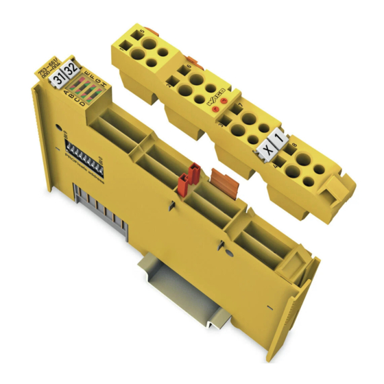
Device Description WAGO I/O System 750 753-661/000-004 4FDI 24V PROFIsafe View Figure 1: View Table 3: Legend for Figure “View” Pos. Description Details See Section Marking possibility with Mini- Status-LEDs “Device Description” > “Display Elements” Data contacts “Device Description” > “Connectors”... -
Page 19: Connectors
WAGO I/O System 750 Device Description 753-661/000-004 4FDI 24V PROFIsafe Connectors 3.2.1 Data Contacts/Local Bus Communication between the fieldbus coupler/controller and the I/O modules as well as the system supply of the I/O modules is carried out via the local bus. The contacting for the local bus consists of 6 data contacts, which are available as self-cleaning gold spring contacts. -
Page 20: Power Jumper Contacts/Field Supply
Device Description WAGO I/O System 750 753-661/000-004 4FDI 24V PROFIsafe 3.2.2 Power Jumper Contacts/Field Supply Risk of injury due to sharp-edged blade contacts! The blade contacts are sharp-edged. Handle the I/O module carefully to prevent injury. Do not touch the blade contacts. - Page 21 WAGO I/O System 750 Device Description 753-661/000-004 4FDI 24V PROFIsafe Use supply modules for ground (earth)! The I/O module has no power jumper contacts for receiving and transmitting the earth potential. Use a supply module when an earth potential is needed for the subsequent I/O modules.
-
Page 22: Cage Clamp ® Connectors
Device Description WAGO I/O System 750 753-661/000-004 4FDI 24V PROFIsafe 3.2.3 CAGE CLAMP ® Connectors Figure 4: CAGE CLAMP ® Connectors Table 5: Legend for Figure “CAGE CLAMP ® Connectors” Input Channel Connector Function Digital input I1 Clock output T1... -
Page 23: Display Elements
WAGO I/O System 750 Device Description 753-661/000-004 4FDI 24V PROFIsafe Display Elements Figure 5: Indicators, Inputs 1 ... 4 Table 6: Legend for Figure “Indicators, Inputs 1 ... 4” Input Designation LED Status Function Channel Input I1: input voltage for logical... -
Page 24: Figure 6: Communication/I/O Module Status Indicators
PROFIsafe communication error (CRC2 flashing error), watchdog time (F_WD_Time) 1 Hz exceeded Parameterization OK F I/O module selected via WAGO-I/O- CHECK iParameters invalid or F_iPar_CRC set flashing to value not equal to iPar_CRC 1 Hz Parameterization iParameters were transferred to the F... -
Page 25: Operating Elements
WAGO I/O System 750 Device Description 753-661/000-004 4FDI 24V PROFIsafe Operating Elements You can use the coding switch located on the side of the F I/O module to set the PROFIsafe address. Figure 7: Coding Switch for the PROFIsafe Address (set to 1018) -
Page 26: Schematic Diagrams
Device Description WAGO I/O System 750 753-661/000-004 4FDI 24V PROFIsafe Schematic Diagrams Figure 8: Schematic Diagram 3.5.1 Input Block Diagram Figure 9: Input Block Diagram Manual Version 1.0.0, valid from HW/SW Version 01/01... -
Page 27: Technical Data
500 V system voltage/field level (power Isolation (peak value) jumper contacts) 3.6.3 Communication Table 11: Technical Data – Communication 750-375, SW 10 or higher Usable fieldbus couplers/controllers 750-377, SW 10 or higher GSD specification V2.4 See the information in the manual for... -
Page 28: Digital Inputs
Device Description WAGO I/O System 750 753-661/000-004 4FDI 24V PROFIsafe 3.6.4 Digital Inputs Table 12: Technical Data – Digital Inputs Inputs I1 … I4 4 inputs, type 1 per IEC 61131-2 4 × Cat. 2/PL d per ISO 13849-1 2 × Cat. 4/PL e per ISO 13849-1 4 ×... -
Page 29: Safety Parameters
WAGO I/O System 750 Device Description 753-661/000-004 4FDI 24V PROFIsafe 3.6.6 Safety Parameters 3.6.6.1 Single-Channel Safety Application, Duration of Use: 20 Years Table 14: Safety Parameters for Single-Channel Safety Application – 20 Years Maximum safety integrity level SIL 2 per IEC 62061... -
Page 30: Dual-Channel Safety Application, Duration Of Use: 20 Years
Device Description WAGO I/O System 750 753-661/000-004 4FDI 24V PROFIsafe 3.6.6.2 Dual-Channel Safety Application, Duration of Use: 20 Years Table 15: Safety Parameters for Dual-Channel Safety Application – 20 Years Maximum safety integrity level SIL 3 per IEC 62061 Maximum safety integrity level... -
Page 31: Connection Type
WAGO I/O System 750 Device Description 753-661/000-004 4FDI 24V PROFIsafe 3.6.7 Connection Type Table 16: Technical Data – Field Wiring Connection technology CAGE CLAMP ® Conductor cross-section 0.08 mm² … 2.5 mm², AWG 28 … 14 Strip length 8 mm … 9 mm / 0.33 in Table 17: Technical Data –... -
Page 32: Safety Response Time
Device Description WAGO I/O System 750 753-661/000-004 4FDI 24V PROFIsafe 3.6.9 Safety Response Time For the safety response time, take into account the execution times of the local bus and fieldbus, as well as the cycle time of the safe PLC! - Page 33 WAGO I/O System 750 Device Description 753-661/000-004 4FDI 24V PROFIsafe Table 21: Safety Response Time of the Digital Inputs T(SR) in ms in Single-Channel Operation Parameter Short Short Circuit Test Activated Circuit Input filter Maximum Test pulse duration in ms...
-
Page 34: Safety Response Time Of The Digital Inputs In Dual-Channel Applications
Device Description WAGO I/O System 750 753-661/000-004 4FDI 24V PROFIsafe Table 21: Safety Response Time of the Digital Inputs T(SR) in ms in Single-Channel Operation Parameter Short Short Circuit Test Activated Circuit Input filter Maximum Test pulse duration in ms... -
Page 35: Approvals
Device Description 753-661/000-004 4FDI 24V PROFIsafe Approvals For current approvals, please go to: www.wago.com/<Item number>. Functional safety evaluations by TÜV Rheinland The module 753-661/000-004 has been evaluated by UL in accordance with the standards UL/CSA 61010-1, UL/CSA 61010-2-201 and UL 121201, CSA-C22.2 No. -
Page 36: Applications
Device Description WAGO I/O System 750 753-661/000-004 4FDI 24V PROFIsafe 3.7.1 Applications The F I/O module can be used in the following applications: • IEC 62061:2021 up to SIL 3 • EN 61511-1:2017 + A1:2017 up to SIL 3 • IEC 61511-1:2016 + COR1:2016 + A1:2017 up to SIL 3 •... -
Page 37: Standards And Guidelines
WAGO I/O System 750 Device Description 753-661/000-004 4FDI 24V PROFIsafe Standards and Guidelines The F I/O module 753-661/000-004 meets the following standards and guidelines: Safety of machinery – IEC 61508/EN 61508, Parts 1-7 Functional safety of safety-related electrical / electronic / programmable electronic control systems Safety of machinery –... -
Page 38: Transport And Storage Conditions
Device Description WAGO I/O System 750 753-661/000-004 4FDI 24V PROFIsafe 3.8.1 Transport and Storage Conditions During transport and storage, the F I/O modules must be protected against undue stress such as mechanical loads, temperature, humidity and aggressive atmospheres. The F I/O modules should be stored in the original packaging when possible, which offers optimal protection during transport. -
Page 39: Process Image
WAGO I/O System 750 Process Image 753-661/000-004 4FDI 24V PROFIsafe Process Image The 753-661/000-004 F I/O module occupies 7 data bytes in the input process image and 5 data bytes in the output process image on the fieldbus. The secure PROFIsafe telegrams to send and receive are stored in input bytes 0 ... - Page 40 Process Image WAGO I/O System 750 753-661/000-004 4FDI 24V PROFIsafe PROFIsafe status byte Table 25: PROFIsafe Status Byte Bit 7 Bit 6 Bit 5 Bit 4 Bit 3 Bit 2 Bit 1 Bit 0 Cons_nr_ Toggle_d FV_activat WD_Time CE_CRC ChF_Ack_...
-
Page 41: Mounting
WAGO I/O System 750 Mounting 753-661/000-004 4FDI 24V PROFIsafe Mounting Do not work when devices are energized! High voltage can cause electric shock or burns. Switch off all power to the device prior to performing any installation, repair or maintenance work. -
Page 42: Mounting Sequence
Don't forget the bus end module! Always plug a bus end module (e.g. 750-600) onto the end of the fieldbus node! You must always use a bus end module at all fieldbus nodes with WAGO I/O System 750 fieldbus couplers or controllers to guarantee proper data transfer. -
Page 43: Inserting And Removing Devices
WAGO I/O System 750 Mounting 753-661/000-004 4FDI 24V PROFIsafe Inserting and Removing Devices Do not work when devices are energized! High voltage can cause electric shock or burns. Switch off all power to the device prior to performing any installation, repair or maintenance work. -
Page 44: Removing The I/O Module
Mounting WAGO I/O System 750 753-661/000-004 4FDI 24V PROFIsafe 5.2.2 Removing the I/O Module Note Remove pluggable wiring! Before removing a 753 Series I/O Module from the node, you must first remove the plug (pluggable wiring) from the I/O module (see section “Plug Removal”)! -
Page 45: I/O Modules With Pluggable Wiring Level (Series 753)
WAGO I/O System 750 Mounting 753-661/000-004 4FDI 24V PROFIsafe I/O Modules with Pluggable Wiring Level (Series 753) For wiring, a plug is plugged into the bottom of the module of all 753 Series I/O modules. The plug can be completely removed together with the wiring, simplifying replacement of defective modules from the assembly. -
Page 46: Coding
Mounting WAGO I/O System 750 753-661/000-004 4FDI 24V PROFIsafe Figure 15: Attachment of Cable Binders 5.3.1 Coding Coding using small plastic pins and sockets facilitates mating of the I/O module with the appropriate plug. Insert the pin into the socket. -
Page 47: Figure 18: Plugging The Plug Into Place
WAGO I/O System 750 Mounting 753-661/000-004 4FDI 24V PROFIsafe Figure 18: Plugging the Plug into Place When the plug is removed the sockets remain in the I/O module. The coded plug can only fit in the corresponding coded I/O module (see figures below). -
Page 48: Plug Removal
Mounting WAGO I/O System 750 753-661/000-004 4FDI 24V PROFIsafe 5.3.2 Plug Removal Remove the plug from the I/O module by pulling the orange pull tab on the plug toward the top of the I/O module. Figure 20: Pulling the Pull Tab The plug detaches from the I/O module. -
Page 49: Connect Devices
Do not connect more than one conductor at one single connection! If more than one conductor must be routed to one connection, these must be connected in an up-circuit wiring assembly, for example using WAGO feed- through terminals. For opening the CAGE CLAMP insert the actuating tool into the opening ®... -
Page 50: Additional Information On The Power Supply
For the WAGO I/O System, a capacitive buffer module (e.g., Item No. 787-880) can be used to bridge short duration voltage drops or load fluctuations in the field supply voltage. -
Page 51: Commissioning
WAGO I/O System 750 Commissioning 753-661/000-004 4FDI 24V PROFIsafe Commissioning Commissioning and Maintenance Instructions Only qualified persons may perform the work! Adding and commissioning F I/O modules may only be carried out by personnel trained in safety-related procedures! Check safety functions! -
Page 52: Adding Or Replacing Components
The PROFIsafe address set on the coding switch of the F I/O module has priority over the PROFIsafe address set by the WAGO parameterization tool. Only when the address set on the coding switch equals 0 does the setting of the PROFIsafe address using the WAGO parameterization tool take effect. -
Page 53: Setting The Profisafe Address Using The Coding Switch
To configure the PROFIsafe address through storage in the iParameter set of the F I/O module, set the PROFIsafe address in the WAGO parameterization tool to the required value and save the current iParameter set to the F I/O module. -
Page 54: Parameterization Of The F I/O Module With The Wago Parameterization Tool
Commissioning WAGO I/O System 750 753-661/000-004 4FDI 24V PROFIsafe Parameterization of the F I/O Module with the WAGO Parameterization Tool Check safety functions! Before commissioning, all the specified effectiveness of all safety functions must be verified. Check the iParameter settings! After the parameterization of the F I/O module, the parameters read back from the F I/O module must be compared to the expected values and confirmed. -
Page 55: Online Mode
To access existing parameter files, click the [Open] button in the WAGO Safety Editor toolbar. In the Open WAGO iParameter Set dialog, select the folder from which the file is to be loaded and enter a name for the parameter file. To load this file from the specified location, click the [Open] button. -
Page 56: Writing Iparameters To The Module Or Parameter File
If the iParameter verification fails, an error message is output. The verified iParameter values are then read out of the F I/O module and displayed in the Verification column of the iParameter set table of WAGO Safety Editor. Now compare the iParameter values of the Input column to the values of the Verification column row by row. -
Page 57: Offline Mode
7.3.2.2 Writing to a Parameter File In the Input column of the iParameter set table of WAGO Safety Editor, you can make the desired changes to the iParameter values. After selecting an iParameter, you can select the parameter values from a selection field or enter them directly. -
Page 58: Other Services For Offline And Online Mode
To print the results of the comparison between to iParameter sets, click the [Print] button. To exit the WAGO Safety Editor comparison dialog, click the [Close] button. To close WAGO Safety Editor, click the [Exit] button in the WAGO Safety Editor toolbar. 7.3.3.2... -
Page 59: Description Of The Call Options
If you do not know the current password, you can use the master password to assign a new one. The master password is 16 characters long and is )[4~>#%qM}x=,:$~. To close WAGO Safety Editor, click the [Exit] button in the WAGO Safety Editor toolbar. 7.3.4 Description of the Call Options WAGO Safety Editor can be started with various call options. -
Page 60: Direct Start From The Operating System
Editor 75x with the current language and communication settings. WAGO Safety Editor starts in ONLINE mode. The communication is performed via ETHERNET TCP/IP. If you exit the configuration of the F I/O module and close Safety Editor, WAGO- I/O-CHECK also closes. 7.3.4.4... -
Page 61: Direct Start From The Configuration Program (Module Level Tci Offline)
OFFLINE) In the configuration program of the safe PLC, select an F I/O module and launch WAGO Safety Editor 75x via the “WAGO Safety-Editor 75x” TCI link. The configuration program passes the current language setting to WAGO Safety Editor. WAGO Safety Editor starts in OFFLINE mode. -
Page 62: Input Filter Time Parameter
Commissioning WAGO I/O System 750 753-661/000-004 4FDI 24V PROFIsafe 7.3.5.1 Input Filter Time Parameter Configuring the input filter time changes the safety response time If you change the Input Filter Time parameter, then the safety response time also changes. You can read more about this in section “Safety Response Time.”... -
Page 63: Short Circuit Test Ix Parameter
WAGO I/O System 750 Commissioning 753-661/000-004 4FDI 24V PROFIsafe 7.3.5.2 Short Circuit Test Ix Parameter Protected installation of signal lines required When connecting signal lines to the digital inputs of the F I/O module, it is essential to ensure that signals are transmitted within a cable or non-metallic sheathed cable only if their short circuit does not lead to a dangerous failure of the safety function, or if they are signals supplied by different clock outputs. -
Page 64: Table 29: Error Detection
Commissioning WAGO I/O System 750 753-661/000-004 4FDI 24V PROFIsafe Using the cyclical tests of the digital inputs, the F I/O module detects the following errors at the digital inputs: Table 29: Error Detection Error Operating Mode (x = 1 ... 4,... -
Page 65: Test Pulse Duration Parameter
WAGO I/O System 750 Commissioning 753-661/000-004 4FDI 24V PROFIsafe 7.3.5.3 Test Pulse Duration Parameter Configuring the test pulse duration changes the safety response time If you change the Test Pulse Duration parameter, then the safety response time also changes. You can read more about this in section “Safety Response Time.”... -
Page 66: Table 30: Equivalent Pre-Evaluation
Commissioning WAGO I/O System 750 753-661/000-004 4FDI 24V PROFIsafe The F I/O module can be used to create two channel pairs from the four digital inputs: • Channel pair 1: digital inputs I1 and I2 • Channel pair 2: digital inputs I3 and I4 You can set the value of the Pre-Evaluation parameter separately for each channel pair. -
Page 67: Discrepancy Time Ix And Ix+1 Parameter
WAGO I/O System 750 Commissioning 753-661/000-004 4FDI 24V PROFIsafe Table 31: Antivalent Pre-Evaluation Inputs Process Image Signal Status Ix+1 Ix+1 Invalid 1-signal 0-signal Invalid After the amount of time specified in the Discrepancy Time setting has elapsed, an invalid signal state causes a discrepancy error to be detected, which in turn causes the channel pair in question to be passivated and the “Discrepancy Time... - Page 68 Commissioning WAGO I/O System 750 753-661/000-004 4FDI 24V PROFIsafe You can use the value of the parameter to specify the maximum permissible time for a deviation (invalid signal state) of the two input signal states of the valence rule. The F I/O module begins discrepancy monitoring as soon as a deviation of the input signal states from the valence rule is detected.
- Page 69 WAGO I/O System 750 Commissioning 753-661/000-004 4FDI 24V PROFIsafe If the process image of the F I/O module transfers a 0-signal due to the input signal states, and a deviation of the input signal states from the valence rule is then detected, discrepancy time monitoring starts.
-
Page 70: Table 32: Maximum Duration Of A Deviation From The Valence Rule To Avoid
Commissioning WAGO I/O System 750 753-661/000-004 4FDI 24V PROFIsafe Maximum Duration of a Deviation from the Valence Rule to Avoid Unwanted Discrepancy Errors To avoid unwanted discrepancy errors and the resulting passivation of the channel pair during error-free operation, it is necessary to ensure that the maximum duration of the deviation from the valence rule is smaller than that specified in the following formula. -
Page 71: Table 33: Minimum Duration Of A Deviation From The Valence Rule To Detect
WAGO I/O System 750 Commissioning 753-661/000-004 4FDI 24V PROFIsafe Minimum Duration of a Deviation from the Valence Rule to Detect a Discrepancy Error A discrepancy error can be detected as soon as the deviation from the valence rule is greater than the value determined in section “Maximum Duration of a Deviation from the Valence Rule to Avoid Unwanted Discrepancy Errors.”... -
Page 72: Restart Inhibit Ix And Ix+1 Parameter
Commissioning WAGO I/O System 750 753-661/000-004 4FDI 24V PROFIsafe 7.3.5.6 Restart Inhibit Ix and Ix+1 Parameter Measures required if the Restart Inhibit parameter is set to “Deactivated” If you have set the Restart Inhibit parameter to “Deactivated” and the F I/O module outputs the diagnostic message “Discrepancy time exceeded,”... -
Page 73: Operating Mode Parameter
WAGO I/O System 750 Commissioning 753-661/000-004 4FDI 24V PROFIsafe 7.3.5.7 Operating Mode Parameter Evaluation of input signal states in “Rotary Table” operating mode: If you have set the Operating Mode to the “Rotary table” value, the temporal logic evaluation of the signal state must be performed by a suitable function block in the safe PLC. -
Page 74: Programming The Safe Plc
• Use of a suitable programming and configuration environment • Selection of an appropriate WAGO fieldbus coupler (PROFINET) • Use of the valid WAGO device description file (GSD) After selecting a suitable safe PLC, add the bus system (PROFIBUS or PROFINET) to the hardware configuration environment and configure it accordingly (fieldbus parameters, addresses, names etc.). - Page 75 Then adjust the PROFIsafe address and the F parameters of the F I/O module by setting F_iPar_CRC and F_Dest_Add in the hardware configuration environment to the value from the WAGO parameterization tool or the value of the coding switch (depending on the setting). See Appendix > “PROFIsafe“ > “Overview of PROFIsafe F Parameters.”...
-
Page 76: F I/O Module With Ipar Server
The iPar server option is described in a WAGO application note and contains all the descriptions, libraries and sample projects necessary for implementing an iPar server. If the F I/O module is operated in conjunction with the iPar server from WAGO, I/O module replacement for maintenance is possible without manual reparameterization. -
Page 77: Connection Examples
This section generally describes possible applications, in which the functions of the F I/O module for implementation of a safety function are used. For the digital inputs of the F I/O module, you can use the WAGO parameterization tool during individual parameterization to select the "Standard"... -
Page 78: Emergency Off Connection, Single-Channel
Commissioning WAGO I/O System 750 753-661/000-004 4FDI 24V PROFIsafe Ensure protected installation when the short circuit test is activated! With the two clock outputs T1 and T2, you can install the signal lines of at most two contiguous input channels in one common cable. Otherwise, the F I/O module cannot detect short circuits between signal lines of the inputs that are tested with the same clock output. - Page 79 WAGO I/O System 750 Commissioning 753-661/000-004 4FDI 24V PROFIsafe For simple emergency stop applications without single fault security, you can use a digital input for your safety function. You can connect the digital input via a switching element (e.g., an emergency stop switch) either to the associated clock output or directly to the +24 V field supply voltage.
-
Page 80: Emergency Stop Connection, Dual-Channel, Equivalent Pre-Evaluation
F I/O module. Use the WAGO parameterization tool to set the parameters. Set the Pre-Evaluation parameter for the digital inputs used to “Equivalent.” In addition, set the Discrepancy Time parameter to the discrepancy time required for the two switching elements. -
Page 81: Protective Door Monitoring Connection, Dual-Channel, Antivalent Pre-Evaluation
To monitor protective door devices, you can connect the normally open contacts of a safety interlock switch to four digital inputs of the F I/O module. Use the WAGO parameterization tool to set the parameters. Set the Pre-Evaluation parameter for the digital inputs used to “Antivalent.” To have the signal lines of the digital inputs of the F I/O module monitored for short circuits, set the Short Circuit Test parameter for all inputs to “Activated.”... -
Page 82: Connection Example For Digital Inputs In "Rotary Table" Operating Mode (1 Of N)
If you have set the Operating Mode parameter to the value “Rotary Table” using the WAGO parameterization tool, you can connect the normally open contacts of a mode selector switch or several rotary table sensors to the digital inputs of the F I/O module. -
Page 83: Diagnostics
F I/O module. If the safety-related shutdown occurs multiple times, the F I/O module must be replaced. In such cases, return the defective F I/O module to WAGO GmbH & Co. KG for fault analysis. Manual... -
Page 84: Errors And Error Types
Diagnostics WAGO I/O System 750 753-661/000-004 4FDI 24V PROFIsafe Errors and Error Types Table 35: Errors and Error Types Error Error Type Coding Safe Inputs Internal channel error Channel error 0x0280 Short circuit Channel error 0x0201 Overload clock output Channel error... -
Page 85: Behavior In Case Of Error
WAGO I/O System 750 Diagnostics 753-661/000-004 4FDI 24V PROFIsafe Behavior in Case of Error The behavior of the F I/O module in case of error depends on the type of error and is described below: • Channel error • Channel pair error •... -
Page 86: Module Errors
(see section “Diagnostics” > “Error Diagnostics”). If the problem occurs repeatedly, this indicates a defect in the F I/O module. In this case, return the F I/O module to WAGO GmbH & Co. KG for fault analysis. Observe the notes in Section “Firmware Update.”... -
Page 87: Error Diagnostics
The structure of the diagnostic messages is described in the fieldbus coupler manuals. The F I/O module 753-661/000-004 can be operated on the WAGO I/O System 750 fieldbus couplers specified in section “Technical Data” > … > “Communication”: Table 36: Diagnostic Messages... - Page 88 Diagnostics WAGO I/O System 750 753-661/000-004 4FDI 24V PROFIsafe Table 36: Diagnostic Messages Message Description Error Diagnostic type Module diagnostic downloading Coding 0x004A iParameters LED indicator No indicator Description/ Timeout when writing (downloading) the remedy iParameters from the iPar server. Check...
- Page 89 WAGO I/O System 750 Diagnostics 753-661/000-004 4FDI 24V PROFIsafe Table 36: Diagnostic Messages Message Description Firmware update Diagnostic type Module diagnostic required Coding 0x0231 LED indicator Module error: red, flashing at 2 Hz Description/ Checking the firmware image has resulted remedy in an inconsistent state.
- Page 90 Diagnostics WAGO I/O System 750 753-661/000-004 4FDI 24V PROFIsafe Table 36: Diagnostic Messages Message Description Incorrect Diagnostic type Module diagnostic F_Par_Version Coding 0x0046 LED indicator Module error: red PROFIsafe status: red Description/ The set version of F parameter set is remedy incorrect.
- Page 91 WAGO I/O System 750 Diagnostics 753-661/000-004 4FDI 24V PROFIsafe Table 36: Diagnostic Messages Message Description Invalid Diagnostic type Module diagnostic F_Source_Add Coding 0x0042 LED indicator Module error: red PROFIsafe status: red Description/ The PROFIsafe address of the safe remedy controller must be in the range of 1 …...
- Page 92 Diagnostics WAGO I/O System 750 753-661/000-004 4FDI 24V PROFIsafe Table 36: Diagnostic Messages Message Description Overload clock Diagnostic type Channel diagnostics output Coding 0x0286 LED indicator Channel status: red Description/ Clock output of the F I/O module is remedy overloaded. Check the clock output’s wiring.
- Page 93 The F I/O module has entered the safe remedy state and switched off the outputs. If the error occurs repeatedly after restart, immediately replace the F I/O module and send it to WAGO for error analysis. Classification Error Short circuit Diagnostic type Channel diagnostics...
-
Page 94: Acknowledging Error Messages
Diagnostics WAGO I/O System 750 753-661/000-004 4FDI 24V PROFIsafe Acknowledging Error Messages Once they have been corrected, errors can be acknowledged by the controller via the PROFIsafe protocol. 8.5.1 Error Acknowledgment The module supports channel granular passivation. Acknowledgement is performed in accordance with the RIOforFA specifications. - Page 95 WAGO I/O System 750 Diagnostics 753-661/000-004 4FDI 24V PROFIsafe Note manufacturer’s documentation Follow the required procedures listed in the respective controller manufacturer’s documentation. Check and document all safety functions. Only corrected errors are acknowledged with error acknowledgment. Pending errors can only be acknowledged after the error has been corrected.
-
Page 96: Signal Sequence Diagramms
Diagnostics WAGO I/O System 750 753-661/000-004 4FDI 24V PROFIsafe 8.5.2 Signal Sequence Diagramms Figure 32: Signal Sequence: User Acknowledgement of Channel Error Figure 33: Signal Sequence: Communication Error Manual Version 1.0.0, valid from HW/SW Version 01/01... -
Page 97: Service
WAGO I/O System 750 Service 753-661/000-004 4FDI 24V PROFIsafe Service Replacing the F I/O Module The process of replacing an F I/O module with an F I/O module of the same type is described below. Only replace modules when the system is in a safe state! Modules must only be replaced when the system is in a safe state. -
Page 98: F I/O Module With Ipar Server Functionality
Section “Service” > “Replacing the F I/O Module” > “F I/O Module without iPar Server Functionality” > “PROFIsafe Address Set Using the Coding Switch”). When using the WAGO iPar server functionality, follow the procedure found in the corresponding application note. -
Page 99: F I/O Module Without Ipar Server Functionality
WAGO I/O System 750 Service 753-661/000-004 4FDI 24V PROFIsafe When using the WAGO iPar server functionality, follow the procedure found in the corresponding application note. 9.1.3 F I/O Module without iPar Server Functionality 9.1.3.1 PROFIsafe Address Set Using the Coding Switch If the PROFIsafe address of the F I/O module to be replaced is set using the coding switch on the side, i.e., the switch setting does not equal 0, set the... -
Page 100: Firmware Update
Note firmware version! Only firmware intended for the F I/O module can be loaded. You can update firmware on the Series 750 I/O Modules with the software “WAGO I/O-Update 750.” The I/O modules can be updated via the service interface or, for ETHERNET-based fieldbuses, via the fieldbus connection on the fieldbus coupler/controller. - Page 101 Do not close the software during the update. • Only run the software from a local hard disk. Additional Information from WAGO Support! Additional information about the software “WAGO I/O-Update 750” is available through WAGO Support. Manual Version 1.0.0, valid from HW/SW Version 01/01...
-
Page 102: Use In Hazardous Environments
WAGO I/O System 750 753-661/000-004 4FDI 24V PROFIsafe Use in Hazardous Environments The WAGO I/O System 750 (electrical equipment) is designed for use in Zone 2 hazardous areas and shall be used in accordance with the marking and installation regulations. -
Page 103: Marking Configuration Examples
WAGO I/O System 750 Use in Hazardous Environments 103 753-661/000-004 4FDI 24V PROFIsafe 10.1 Marking Configuration Examples 10.1.1 Marking for Europe According to ATEX and IECEx Figure 34: Marking Example per ATEX and IECEx Figure 35: Text Detail – Marking Example per ATEX and IECEx Manual Version 1.0.0, valid from HW/SW Version 01/01... -
Page 104: Table 37: Description Of The Marking Example Per Atex And Iecex
104 Use in Hazardous Environments WAGO I/O System 750 753-661/000-004 4FDI 24V PROFIsafe Table 37: Description of the Marking Example per ATEX and IECEx Marking Text Description TUEV 07 ATEX 554086 X Approving authority or certificate numbers IECEx TUN 09.0001 X... -
Page 105: Figure 36: Marking Example Of An Approved I/O Module Ex I Per Atex And
WAGO I/O System 750 Use in Hazardous Environments 105 753-661/000-004 4FDI 24V PROFIsafe Figure 36: Marking Example of an Approved I/O Module Ex i per ATEX and IECEx Figure 37: Text Detail – Marking Example of an Approved I/O Module Ex i... -
Page 106: Table 38: Description Of The Marking Example Of An Approved I/O Module Ex I Per Atex And Iecex
106 Use in Hazardous Environments WAGO I/O System 750 753-661/000-004 4FDI 24V PROFIsafe Table 38: Description of the Marking Example of an Approved I/O Module Ex i per ATEX and IECEx Marking Text Description TUEV 12 ATEX 106032 X Approving authority or... -
Page 107: Marking For The United States Of America (Nec) And Canada (Cec)
WAGO I/O System 750 Use in Hazardous Environments 107 753-661/000-004 4FDI 24V PROFIsafe 10.1.2 Marking for the United States of America (NEC) and Canada (CEC) Figure 38: Marking Example According to NEC Figure 39: Text Detail – Marking Example According to NEC 500... -
Page 108: Figure 40: Text Detail - Marking Example For Approved I/O Module Ex I
108 Use in Hazardous Environments WAGO I/O System 750 753-661/000-004 4FDI 24V PROFIsafe Figure 40: Text Detail – Marking Example for Approved I/O Module Ex i According to NEC 505 Table 40: Description of Marking Example for Approved I/O Module Ex i According to NEC 505... -
Page 109: Figure 42: Text Detail - Marking Example For Approved I/O Module Ex I
WAGO I/O System 750 Use in Hazardous Environments 109 753-661/000-004 4FDI 24V PROFIsafe Figure 42: Text Detail – Marking Example for Approved I/O Module Ex i According to CEC 18 attachment J Table 42: Description of Marking Example for Approved I/O Module Ex i According to CEC 18... -
Page 110: Installation Regulations
Special Notes including Explosion Protection The following warning notices are to be posted in the immediately proximity of the WAGO I/O System 750 (hereinafter “product”): WARNING – DO NOT REMOVE OR REPLACE FUSED WHILE ENERGIZED! WARNING – DO NOT DISCONNECT WHILE ENERGIZED! WARNING –... - Page 111 40 % due to transient faults (e.g., when powering the field supply). Product components intended for intrinsically safe applications may only be powered by 750-606 or 750-625/000-001 bus supply modules. Only field devices whose power supply corresponds to overvoltage category I or II may be connected to these components.
-
Page 112: Special Notes Regarding Ul Hazardous Location
(LANs) and may not be connected to telephone networks or telecommunication cables • WARNING – The radio receiver module 750-642 may only be used to connect to external antenna 758-910! • WARNING – Product components with fuses must not be fitted into circuits subject to overloads! These include, e.g., motor circuits. -
Page 113: Appendix
I/O modules equipped with safety-related inputs and outputs (so-called F I/O modules) have been developed for the WAGO I/O System 750 without radical changes to the existing 750 Series system. This allows mixed operation of safety- related and non-safety-related I/O modules. -
Page 114: Figure 44: Profisafe Layer Model
114 Appendix WAGO I/O System 750 753-661/000-004 4FDI 24V PROFIsafe Figure 44: PROFIsafe Layer Model The PROFIsafe telegrams are transferred between the safe PLC and the F I/O module via the so-called “black channel.” The “black channel” extends from the PROFINET connection of the PLC, to the fieldbus coupler/controller, the local bus in the node, to the F I/O module. -
Page 115: Individual Parameters (Iparameters)
The individual parameters are used to configure device functions of a safe device such as the F I/O modules of the WAGO I/O System 750. The “WAGO Safety Editor 75x” parameterization tool (SEDI) can be used to set the individual parameters of WAGO F I/O modules. -
Page 116: Overview Of Profisafe F Parameters
The F_SIL parameter specifies the required F_SIL SIL 3 safety integrity level of the F I/O module. The F I/O module supports SIL3. This value is specified by the WAGO device description file (GSD/GSDML). The F_CRC_Length parameter specifies the F_CRC_Length 4-byte CRC length of the CRC2 key to be used in the PROFIsafe telegram. - Page 117 F_Passivation passivation type of the I/O module. The F I/O module supports channel-granular Passivation according to RIOforFA. This value is specified by the WAGO device description file (GSD/GSDML). The F_Block_ID parameter specifies the F_Block_ID format of the F parameter set. The F I/O module only supports the value “1.”...
- Page 118 “F_iPar_CRC” value “0” is a special case. This value switches the F I/O module into test mode. The CRC value (iPar_CRC) is displayed by the WAGO parameterization tool and must be transferred with the configuration tool of the safe PLC to the F parameters of the F I/O/ module.
-
Page 119: Profisafe Certificates
WAGO I/O System 750 Appendix 119 753-661/000-004 4FDI 24V PROFIsafe 11.2.1 PROFIsafe Certificates PROFIsafe Certificates A list of PROFIsafe certificates and PDFs of the certificates are available on the "AUTOMATION Tools and Docs" DVD-ROM (Art. No.: 0888-0412) or on the Internet at: http://www.wago.com. -
Page 120: Glossary
PLC. CPD Tool (Configuration, Parametrization and Diagnosis Tool) The CPD tool can be used to parameterize, configure and diagnose device functions of safe field devices (see also “WAGO Parameterization Tool” and “WAGO Safety Editor”). CRC (Cyclic Redundancy Check) The cyclic redundancy check is a procedure for determining a test value for data in order to detect errors during transmission or storage. - Page 121 WAGO I/O System 750 Glossary 121 753-661/000-004 4FDI 24V PROFIsafe Dangerous Failure Termination of the capacity of a unit to perform the required function (see also “Failure”). DC (Diagnostic Coverage) Diagnostic coverage is the decrease in probability of dangerous hardware failures that result from executing automatic diagnostics tests.
- Page 122 122 Glossary WAGO I/O System 750 753-661/000-004 4FDI 24V PROFIsafe Failure Termination of the capacity of a unit to perform the required function (see also “Dangerous Failure”). FG (Functional Ground) Function ground (FG) is not the same as protective earth (PE) according to VDE 0100 and is only used as an EMC ground connector.
- Page 123 WAGO I/O System 750 Glossary 123 753-661/000-004 4FDI 24V PROFIsafe iParameters See “Individual Parameters.” iPar Server Standardized mechanism for saving and restoring iParameters (iPar) in the non- safe part of a control unit. Minimum Signal Duration Minimum duration of a signal voltage “0” (e.g., open input) on the input of the...
- Page 124 124 Glossary WAGO I/O System 750 753-661/000-004 4FDI 24V PROFIsafe PL (Performance Level) The performance level (PL) specifies the capacity of safety devices to execute a safety function under foreseeable conditions. A PLC (Programmable Logic Controller) is a device used to control a machine or system and is programmed on a digital basis.
- Page 125 WAGO I/O System 750 Glossary 125 753-661/000-004 4FDI 24V PROFIsafe Risk Reduction The required risk reduction is the result of a risk assessment on the basis of which measures are taken to lower the risk of a safety system to an acceptable residual risk.
- Page 126 126 Glossary WAGO I/O System 750 753-661/000-004 4FDI 24V PROFIsafe Short Circuit Test The short circuit test is used to detect a short circuit between two live lines. See also “Cross Circuit Test.” T(SR) (Safety Response Time) Symbol for the safety response time in case of error (see also “Safety Response Time”).
- Page 127 WAGO Safety Editor WAGO Safety Editor (abbreviated SEDI) is required together with WAGO-I/O- CHECK 3.x for configuring the F I/O modules. SEDI is the CPD tool for WAGO F I/O Modules (see also “CPD Tool (Configuration, Parametrization and Diagnosis Tool)”).
-
Page 128: List Of Figures
........49 ® Figure 24: Example of a serial number ..............51 Figure 25: Start View of WAGO Safety Editor ............. 55 Figure 26: Connection 4 × Emergency Off, Single-Channel, Short Circuit Test Activated ..................... 78 Figure 27: Connection 4 × Emergency Off, Single-Channel, Short Circuit Test Deactivated .................... - Page 129 WAGO I/O System 750 List of Figures 129 753-661/000-004 4FDI 24V PROFIsafe Figure 41: Text Detail – Marking Example for Approved I/O Module Ex i According to NEC 506 ................108 Figure 42: Text Detail – Marking Example for Approved I/O Module Ex i According to CEC 18 attachment J ............
-
Page 130: List Of Tables
130 List of Tables WAGO I/O System 750 753-661/000-004 4FDI 24V PROFIsafe List of Tables Table 1: Number Notation ..................9 Table 2: Font Conventions ..................9 Table 3: Legend for Figure “View” ............... 18 Table 4: Legend for Figure “Power Jumper Contacts” ......... 20 Table 5: Legend for Figure “CAGE CLAMP... - Page 131 WAGO I/O System 750 List of Tables 131 753-661/000-004 4FDI 24V PROFIsafe Table 41: Description of Marking Example for Approved I/O Module Ex i According to NEC 506 ................108 Table 42: Description of Marking Example for Approved I/O Module Ex i According to CEC 18 attachment J ............
- Page 132 WAGO GmbH & Co. KG Postfach 2880 • D - 32385 Minden Hansastraße 27 • D - 32423 Minden Phone: +49 571 887 – 0 Fax: +49 571 887 – 844169 E-Mail: info@wago.com Internet: www.wago.com...
Need help?
Do you have a question about the 750 and is the answer not in the manual?
Questions and answers