WAGO -I/O-SYSTEM 750 Manual
2-channel digital output module dc 24 v, shortcircuit protected, high-side switching. 2do 24v dc 2.0a
Hide thumbs
Also See for WAGO-I/O-SYSTEM 750:
- User manual ,
- Manual (450 pages) ,
- User's installation and configuration (335 pages)
Table of Contents
Advertisement
Quick Links
Pos: 2 /Dokumentation allgemein/Einband/Einband Deckblatt @ 9\mod_1285229289866_0.doc @ 64941 @ @ 1
Manual
WAGO-I/O-SYSTEM 750
2DO 24V DC 2.0A
750-502
2-Channel Digital Output Module DC 24 V, short-
circuit protected, high-side switching
Version 1.2.0
Pos: 3 /Alle Serien (Allgemeine Module)/Hinweise zur Dokumentation/Impressum - allgemeine Angaben, Anschriften, Telefonnummern und E-Mail-Adressen @ 3\mod_1219151118203_21.doc @ 21060 @ @ 1
Advertisement
Chapters
Table of Contents

Subscribe to Our Youtube Channel
Related Manuals for WAGO WAGO-I/O-SYSTEM 750


Summary of Contents for WAGO WAGO-I/O-SYSTEM 750
- Page 1 Pos: 2 /Dokumentation allgemein/Einband/Einband Deckblatt @ 9\mod_1285229289866_0.doc @ 64941 @ @ 1 Manual WAGO-I/O-SYSTEM 750 2DO 24V DC 2.0A 750-502 2-Channel Digital Output Module DC 24 V, short- circuit protected, high-side switching Version 1.2.0 Pos: 3 /Alle Serien (Allgemeine Module)/Hinweise zur Dokumentation/Impressum - allgemeine Angaben, Anschriften, Telefonnummern und E-Mail-Adressen @ 3\mod_1219151118203_21.doc @ 21060 @ @ 1...
- Page 2 WAGO-I/O-SYSTEM 750 750-502 2DO 24V DC 2.0A © 2011 by WAGO Kontakttechnik GmbH & Co. KG All rights reserved. WAGO Kontakttechnik GmbH & Co. KG Hansastraße 27 D-32423 Minden Phone: +49 (0) 571/8 87 – 0 Fax: +49 (0) 571/8 87 – 1 69 E-Mail: info@wago.com...
-
Page 3: Table Of Contents
WAGO-I/O-SYSTEM 750 Table of Contents 750-502 2DO 24V DC 2.0A Po s: 5 /Dokumentation allgemein/Verzeichnisse/Inhaltsverzeichnis - Überschrift 1 und Verzeichnis @ 3\mod_1219151230875_21.doc @ 21063 @ @ 1 Table of Contents Notes about this Documentation..............5 Validity of this Documentation..............5 Copyright.................... - Page 4 Table of Contents WAGO-I/O-SYSTEM 750 750-502 2DO 24V DC 2.0A Using Interference-Free Variations of I/O Modules in Safety Related Applications ....................32 Important Notes..................33 Connecting the IO Module to Safety Switching Devices or Safety Modules....................34 7.2.1 General Structure................34 7.2.2...
-
Page 5: Notes About This Documentation
2.0A) of the WAGO-I/O-SYSTEM 750 series and the variants listed in the table below. Po s: 10 /Serie 750 (WAGO-I/O-SYSTEM)/Hinweise zur Dokumentation/Variantenlisten/Variantenliste - 750-xxx - Grundausführung und Variante /000-800 (rückwirkungsfrei) @ 10\mod_1302671594038_21.doc @ 71910 @ @ 1 Table 1: Variants... - Page 6 Notes about this Documentation WAGO-I/O-SYSTEM 750 750-502 2DO 24V DC 2.0A Po s: 13.2 /Dokumentation allgemein/Gliederungselemente/---Seitenwechsel--- @ 3\mod_1221108045078_0.doc @ 21810 @ @ 1 Manual Version 1.2.0...
-
Page 7: Symbols
WAGO-I/O-SYSTEM 750 Notes about this Documentation 750-502 2DO 24V DC 2.0A s: 13.3 /Alle Serien (Allgemeine Module)/Hinweise zur Dokumentation/Symbole @ 3\mod_1217394197593_21.doc @ 21010 @ 2 @ 1 Symbols Personal Injury! Indicates a high-risk, imminently hazardous situation which, if not avoided, will result in death or serious injury. - Page 8 Notes about this Documentation WAGO-I/O-SYSTEM 750 750-502 2DO 24V DC 2.0A Additional Information: Refers to additional information which is not an integral part of this documentation (e.g., the Internet). s: 13.4 /Dokumentation allgemein/Gliederungselemente/---Seitenwechsel--- @ 3\mod_1221108045078_0.doc @ 21810 @ @ 1 Manual Version 1.2.0...
-
Page 9: Number Notation
WAGO-I/O-SYSTEM 750 Notes about this Documentation 750-502 2DO 24V DC 2.0A s: 13.5 /Alle Serien (Allgemeine Module)/Hinweise zur Dokumentation/Zahlensysteme @ 3\mod_1221059454015_21.doc @ 21711 @ 2 @ 1 Number Notation Table 2: Number Notation Number code Example Note Decimal Normal notation... -
Page 10: Important Notes
All changes to the coupler or controller should always be carried out by qualified personnel with sufficient skills in PLC programming. Po s: 16.5 /Serie 750 (WAGO-I/O-SYSTEM)/Wichtige Erläuterungen/Bestimmungsgemäße Verwendung 750-xxxx @ 3\mod_1224064151234_21.doc @ 24070 @ 3 @ 1 2.1.3 Use of the 750 Series in Compliance with Underlying... -
Page 11: Technical Condition Of Specified Devices
The components to be supplied Ex Works, are equipped with hardware and software configurations, which meet the individual application requirements. WAGO Kontakttechnik GmbH & Co. KG will be exempted from any liability in case of changes in hardware or software as well as to non-compliant usage of components. -
Page 12: Safety Advice (Precautions)
All power sources to the device shall be switched off prior to performing any installation, repair or maintenance work. s: 16.10.2 /Serie 750 (WAGO-I/O-SYSTEM)/Wichtige Erläuterungen/Sicherheitshinweise/Gefahr/Gefahr: Einbau 0750-xxxx nur in Gehäusen, Schränken oder elektrischen Betriebsräumen! @ 6\mod_1260180556692_21.doc @ 46731 @ @ 1 Installation only in appropriate housings, cabinets or in electrical operation rooms! The WAGO-I/O-SYSTEM 750 and its components are an open system. - Page 13 WAGO-I/O-SYSTEM 750 Important Notes 750-502 2DO 24V DC 2.0A Do not use any contact spray! Do not use any contact spray. The spray may impair contact area functionality in connection with contamination. s: 16.11.5 /Alle Serien (Allgemeine Module)/Wichtige Erläuterungen/Sicherheitshinweise/Achtung/Achtung: Verpolung vermeiden! @ 6\mod_1260184045744_21.doc @ 46767 @ @ 1...
-
Page 14: Device Description
Po s: 19.2 /Serie 750 (WAGO-I/O-SYSTEM)/Gerätebeschreibung/Beschreibung/I/O-Beschreibung/DO/I/O-Beschreibung 750-05xx 2 DO 3-Leiter (DO, 0 V und PE) @ 5\mod_1246609920281_21.doc @ 36553 @ @ 1 The module has two output channels. Two actuators with ground (earth) wire may be directly connected to signal output DO 1, 0 V and PE (earth potential) or signal output DO 2, 0 V and PE. - Page 15 @ 3\mod_1233756478750_21.doc @ 27102 @ @ 1 The field level and the system level are electrically isolated from one another. Po s: 19.16 /Serie 750 (WAGO-I/O-SYSTEM)/Gerätebeschreibung/Beschreibung/Einsatzbereich/Hinweise/Warnung: Einsatz Variante /xxx-8xx in sicherheitsgerichteten Anwendungen @ 5\mod_1246882860453_21.doc @ 36680 @ @ 1 Using in safety related applications! When using the I/O module ( 750-502 ) in safety-related applications, the instructions and connection examples in Section "Use in safety-related...
-
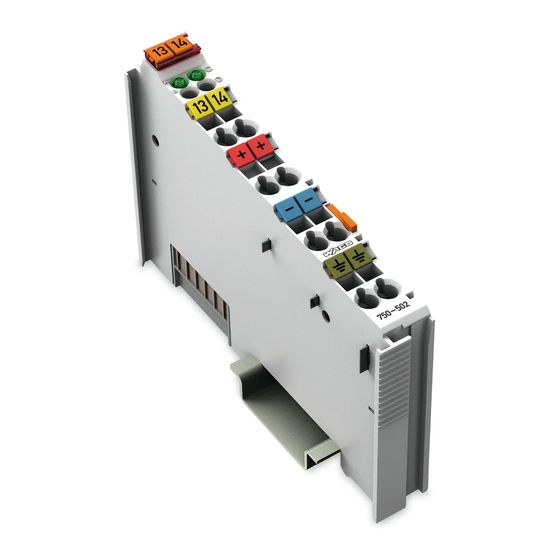
Page 16: View
750-502 2DO 24V DC 2.0A s: 21 /Alle Serien (Allgemeine Module)/Überschriften für alle Serien/Ansicht - Überschrift 2 @ 4\mod_1240984217343_21.doc @ 31958 @ 2 @ 1 View Po s: 22 /Serie 750 (WAGO-I/O-SYSTEM)/Gerätebeschreibung/Ansicht/Digitalausgangsklemmen/Ansicht 750-0502 @ 10\mod_1298296913048_21.doc @ 69743 @ @ 1 13 14 13 14... -
Page 17: Connectors
Do not place the I/O modules on the gold spring contacts in order to avoid soiling or scratching! s: 26.3 /Serie 750 (WAGO-I/O-SYSTEM)/Wichtige Erläuterungen/Sicherheitshinweise/Achtung/Achtung: ESD - Auf gute Erdung der Umgebung achten! @ 7\mod_1266318538667_21.doc @ 50708 @ @ 1 Ensure that the environment is well grounded! The modules are equipped with electronic components that may be destroyed by electrostatic discharge. -
Page 18: Power Contacts/Field Supply
Fig 3: Power jumper contacts Po s: 29.3 /Serie 750 (WAGO-I/O-SYSTEM)/Wichtige Erläuterungen/Sicherheitshinweise/Achtung/Achtung: Maximaler Strom Leistungskontakte 10 A @ 3\mod_1226499143500_21.doc @ 25029 @ @ 1 Do not exceed maximum current via power contacts! The maximum current to flow through the power contacts is 10 A. -
Page 19: Cage Clamp ® Connections
WAGO-I/O-SYSTEM 750 Device Description 750-502 2DO 24V DC 2.0A s: 31 /Serie 750 (WAGO-I/O-SYSTEM)/Gerätebeschreibung/Anschlüsse/CAGE CLAMP-Anschlüsse - Überschrift 3 @ 6\mod_1256296337770_21.doc @ 43674 @ 3 @ 1 ® 3.2.3 CAGE CLAMP Connections Po s: 32 /Serie 750 (WAGO-I/O-SYSTEM)/Gerätebeschreibung/Anschlüsse/Digitalausgangsklemmen/Anschlüsse 750-0502 @ 10\mod_1298373025326_21.doc @ 69867 @ @ 1... -
Page 20: Display Elements
Po s: 36 /Alle Serien (Allgemeine Module)/Überschriften für alle Serien/Bedienelemente - Überschrift 2 @ 4\mod_1239191655456_21.doc @ 30439 @ 2 @ 1 Operating Elements Po s: 37 /Serie 750 (WAGO-I/O-SYSTEM)/Gerätebeschreibung/Bedienelemente/Bedienelemente Busklemme 750-xxxx nicht vorhanden @ 4\mod_1236322031125_21.doc @ 28063 @ @ 1 The I/O module 750-502 has no operating elements. -
Page 21: Schematic Diagram
39 /Alle Serien (Allgemeine Module)/Überschriften für alle Serien/Schematisches Schaltbild - Überschrift 2 @ 4\mod_1240984441312_21.doc @ 31967 @ 2 @ 1 Schematic Diagram Po s: 40 /Serie 750 (WAGO-I/O-SYSTEM)/Gerätebeschreibung/Schematische Schaltbilder/Digitalausgangsklemmen/Schematisches Schaltbild 750-0502 @ 10\mod_1298296828802_21.doc @ 69735 @ @ 1 DO 1... -
Page 22: Technical Data
42 /Alle Serien (Allgemeine Module)/Überschriften für alle Serien/Technische Daten - Überschrift 2 @ 3\mod_1232967587687_21.doc @ 26924 @ 2 @ 1 Technical Data Po s: 43 /Serie 750 (WAGO-I/O-SYSTEM)/Gerätebeschreibung/Technische Daten/Digitalausgangsklemmen/Technische Daten 750-0502 @ 10\mod_1298296865613_21.doc @ 69739 @ 3333 @ 1 3.6.1... -
Page 23: Approvals
Po s: 50.6 /Dokumentation allgemein/Gliederungselemente/------Leerzeile------ @ 3\mod_1224662755687_0.doc @ 24460 @ @ 1 Po s: 51 /Serie 750 (WAGO-I/O-SYSTEM)/Gerätebeschreibung/Zulassungen/Zulassungen Busklemme 750-xxxx Ex, nur Variante /000-800 @ 10\mod_1302613660663_21.doc @ 71866 @ @ 1 The following Ex approvals have been granted to the variation 750-502/000-800: Po s: 52 /Alle Serien (Allgemeine Module)/Zulassungen/Ex Zulassungen/cULus (ANSI/ISA 12.12.01) Class I, Div2 ABCD T4 @ 3\mod_1224054791812_0.doc @ 24014 @ @ 1... -
Page 24: Standards And Guidelines
Po s: 57 /Alle Serien (Allgemeine Module)/Überschriften für alle Serien/Normen und Richtlinien - Überschrift 2 @ 4\mod_1242804031875_21.doc @ 33646 @ 2 @ 1 Standards and Guidelines Pos: 58 /Serie 750 (WAGO-I/O-SYSTEM)/Gerätebeschreibung/Normen und Richtlinien/EMV-Normen Busklemme 750-xxxx, ohne Variantenangabe @ 4\mod_1242803944015_21.doc @ 33642 @ @ 1 750-502 I/O modules meet the following requirements on emission and immunity of interference: Pos: 59 /Alle Serien (Allgemeine Module)/Normen und Richtlinien/EMV CE-Störaussendung EN 61000-6-4: 2007 @ 4\mod_1242798273984_21.doc @ 33602 @ @ 1... -
Page 25: Assembly
DI4. s: 65.4 /Serie 750 (WAGO-I/O-SYSTEM)/Wichtige Erläuterungen/Sicherheitshinweise/Achtung/Achtung: Aneinanderreihen von Busklemmen nur bei offener Nut! @ 6\mod_1256193351448_21.doc @ 43417 @ @ 1 Assemble the I/O modules in rows only if the grooves are open! Please take into consideration that some bus modules have no or only a few power jumper contacts. -
Page 26: Inserting And Removing Devices
65.7 /Serie 750 (WAGO-I/O-SYSTEM)/Montieren/Geräte einfügen und entfernen - Überschrift 2 @ 3\mod_1231768483250_21.doc @ 25950 @ 2 @ 1 Inserting and Removing Devices Po s: 65.8 /Serie 750 (WAGO-I/O-SYSTEM)/Wichtige Erläuterungen/Sicherheitshinweise/Gefahr/Gefahr: Vorsicht bei der Unterbrechung von FE! @ 6\mod_1256193919214_21.doc @ 43423 @ @ 1 Use caution when interrupting the PE! Make sure that people or equipment are not placed at risk when removing an I/O module and the associated PE interruption. -
Page 27: Removing The I/O Module
(if any) to the fieldbus coupler/controller or to the previous or possibly subsequent I/O module are established. Po s: 65.11 /Serie 750 (WAGO-I/O-SYSTEM)/Montieren/Busklemme entfernen @ 4\mod_1239169375203_21.doc @ 30334 @ 3 @ 1 4.2.2 Removing the I/O Module Remove the I/O module from the assembly by pulling the release tab. -
Page 28: Connect Devices
67 /Alle Serien (Allgemeine Module)/Überschriften für alle Serien/Geräte anschließen - Überschrift 1 @ 3\mod_1234172889468_21.doc @ 27460 @ 1 @ 1 Connect Devices Po s: 68 /Serie 750 (WAGO-I/O-SYSTEM)/Anschließen/Leiter an CAGE CLAMP anschließen - Überschrift 2 und Text @ 3\mod_1225448660171_21.doc @ 24928 @ 2 @ 1 ®... -
Page 29: Connection Examples
70 /Alle Serien (Allgemeine Module)/Überschriften für alle Serien/Anschlussbeispiele - Überschrift 2 @ 4\mod_1240996036328_21.doc @ 32010 @ 2 @ 1 Connection Examples Po s: 71 /Serie 750 (WAGO-I/O-SYSTEM)/Anschließen/Anschlussbeispiele/Digitalausgangsklemmen/Anschlussbeispiele 750-0502 @ 10\mod_1298558077757_21.doc @ 70203 @ 3333 @ 1 5.2.1 2-Conductor Connection, ungrounded... -
Page 30: 3-Conductor Connection, Ungrounded
Connect Devices WAGO-I/O-SYSTEM 750 750-502 2DO 24V DC 2.0A 5.2.3 3-Conductor Connection, ungrounded 13 14 750-502 Figure 13: Connecting diagram 3-conductor connection, ungrounded 5.2.4 3-Conductor Connection, grounded 13 14 750-502 Figure 14: Connecting diagram 3-conductor connection, grounded Po s: 72 /Dokumentation allgemein/Gliederungselemente/---Seitenwechsel--- @ 3\mod_1221108045078_0.doc @ 21810 @ @ 1 Manual Version 1.2.0... -
Page 31: Process Image
73 /Alle Serien (Allgemeine Module)/Überschriften für alle Serien/Prozessabbild - Überschrift 1 @ 4\mod_1240983067828_21.doc @ 31942 @ 1 @ 1 Process Image Po s: 74 /Serie 750 (WAGO-I/O-SYSTEM)/Prozessabbild Klemmenbus/Hinweis: Prozessabbildmapping ohne Status-/Controlbyte @ 6\mod_1256126797251_21.doc @ 43340 @ @ 1 Mapping of process data in the process image of fieldbus systems The representation of the process data of some I/O modules or their variations in the process image depends on the fieldbus coupler/controller used. -
Page 32: Using Interference-Free Variations Of I/O Modules In Safety Related Applications
Using Interference-Free Variations of I/O Modules in Safety Related ApplicationsWAGO-I/O-SYSTEM 750 750-502 2DO 24V DC 2.0A s: 77.1 /Serie 750 (WAGO-I/O-SYSTEM)/Einsatz in sicherheitsgerichteten Anwendungen/Einleitung - rückwirkungsfreie Varianten @ 6\mod_1258973563064_21.doc @ 44681 @ 1 @ 1 Using Interference-Free Variations of I/O Modules in Safety Related Applications The variation 750-502/xxx-8xx of the I/O module 750-502 (designation “... -
Page 33: Important Notes
Using Interference-Free Variations of I/O Modules in Safety Related Applications 750-502 2DO 24V DC 2.0A s: 77.4 /Serie 750 (WAGO-I/O-SYSTEM)/Einsatz in sicherheitsgerichteten An wendungen/Hinweise zum Einsatz in Sicherheitsanwendungen @ 6\mod_1258974811 438_21.doc @ 44688 @ 2 @ 1 Einsatz der rückwirkungsfreien Digitalausgangsklemme in Sicherheitsanwendungen... -
Page 34: Connecting The Io Module To Safety Switching Devices Or Safety Modules
Using Interference-Free Variations of I/O Modules in Safety Related ApplicationsWAGO-I/O-SYSTEM 750 750-502 2DO 24V DC 2.0A s: 77.6 /Serie 750 (WAGO-I/O-SYSTEM)/Einsatz in sicherheitsgerichteten Anwendungen/Allgemeiner Aufbau einer Potentialgruppe - rückwirkungsfreie Varianten @ 6\mod_1258973074755_21.doc @ 44664 @ 23 @ 1 Connecting the IO Module to Safety Switching Devices or Safety Modules 7.2.1... -
Page 35: Examples Of Connection
Using Interference-Free Variations of I/O Modules in Safety Related Applications 750-502 2DO 24V DC 2.0A s: 79 /Serie 750 (WAGO-I/O-SYSTEM)/Einsatz in sicherheitsgerichteten Anw endungen/Anschlussbeispiele/Anschlussbeispiel 2/4-Kanal-Digitalausgangsklemmen i n Sicherheitsanwendungen @ 6\mod_1259219930757_21.doc @ 45290 @ 3 @ 1 Einsatz der rückwirkungsfreien Digitalausgangsklemme in Sicherheitsanwendungen 7.2.2... - Page 36 Using Interference-Free Variations of I/O Modules in Safety Related ApplicationsWAGO-I/O-SYSTEM 750 750-502 2DO 24V DC 2.0A Po s: 80 /Dokumentation allgemein/Gliederungselemente/---Seitenwechsel--- @ 3\mod_1221108045078_0.doc @ 21810 @ @ 1 Manual Version 1.2.0...
-
Page 37: Use In Hazardous Environments
81.1 /Alle Serien (Allgemeine Module)/Einsatz in Ex-Bereichen/Einsatz in explosionsgefährdeten Bereichen - Überschrift 1 @ 3\mod_1224075191281_21.doc @ 24084 @ 1 @ 1 Use in Hazardous Environments Po s: 81.2 /Serie 750 (WAGO-I/O-SYSTEM)/Einsatz in Ex-Bereichen/Einsatzbereich Serie 750 @ 3\mod_1234272230203_21.doc @ 27500 @ @ 1 The WAGO-I/O-SYSTEM 750 (electrical equipment) is designed for use in Zone 2 hazardous areas. -
Page 38: Identification
81.4 /Serie 750 (WAGO-I/O-SYSTEM)/Einsatz in Ex-Bereichen/Kennzeichnung - Überschrift 2 @ 3\mod_1224157499140_21.doc @ 24182 @ 2 @ 1 Identification Po s: 81.5 /Serie 750 (WAGO-I/O-SYSTEM)/Einsatz in Ex-Bereichen/Kennzeichnung für Europa gemäß CENELEC und IEC - Überschrift 3 @ 3\mod_1224157620203_21.doc @ 24185 @ 3 @ 1 8.1.1 For Europe according to CENELEC and IEC Po s: 81.6 /Serie 750 (WAGO-I/O-SYSTEM)/Einsatz in Ex-Bereichen/Bedruckung gemäß... -
Page 39: Figure 20: Example Of Side Marking Of Ex I And Iec Ex I Approved I/O Modules
750-502 2DO 24V DC 2.0A s: 81.8 /Serie 750 (WAGO-I/O-SYSTEM)/Einsatz in Ex-Bereichen/Bedruckung gemäß Ex i und IEC Ex i @ 7\mod_1274338578856_21.doc @ 56679 @ @ 1 Figure 20: Example of side marking of Ex i and IEC Ex i approved I/O modules Figure 21: Inscription text detail acc. -
Page 40: Table 14: Description Of The Inscription
Use in Hazardous Environments WAGO-I/O-SYSTEM 750 750-502 2DO 24V DC 2.0A Table 14: Description of the inscription Inscription text Description TÜV 07 ATEX 554086 X Approving authority or TUN 09.0001X certificate numbers Dust Device group: All except mining 3(1)D Device category: Zone 22 device (Zone 20 subunit) -
Page 41: For America According To Nec 500
WAGO-I/O-SYSTEM 750 Use in Hazardous Environments 750-502 2DO 24V DC 2.0A s: 81.10 /Serie 750 (WAGO-I/O-SYSTEM)/Einsatz in Ex-Bereichen/Kennzeichnung für Amerika gemäß NEC - Überschrift 3 @ 3\mod_1224158423187_21.doc @ 24188 @ 3 @ 1 8.1.2 For America according to NEC 500 Po s: 81.11 /Serie 750 (WAGO-I/O-SYSTEM)/Einsatz in Ex-Bereichen/Bedruckung gemäß... -
Page 42: Installation Regulations
Po s: 81.16 /Dokumentation allgemein/Gliederungselemente/------Leerzeile------ @ 3\mod_1224662755687_0.doc @ 24460 @ @ 1 Po s: 81.17 /Dokumentation allgemein/Gliederungselemente/------Leerzeile------ @ 3\mod_1224662755687_0.doc @ 24460 @ @ 1 Po s: 81.18 /Serie 750 (WAGO-I/O-SYSTEM)/Einsatz in Ex-Bereichen/Achtung: Errichtungsbestimmungen Serie 750 beachten @ 3\mod_1224158893890_21.doc @ 24191 @ @ 1 Notice the following points... -
Page 43: Special Conditions For Safe Operation Of The Atex And Iec Ex (Acc. Demko 08 Atex 142851X And Iecex Ptb 07.0064)
Use in Hazardous Environments 750-502 2DO 24V DC 2.0A s: 81.20 /Serie 750 (WAGO-I/O-SYSTEM)/Einsatz in Ex-Bereichen/Besondere Bedingungen für den sicheren ATEX- und IEC-Ex-Betrieb gem. DEMKO 08 ATEX 142851X & IECEx @ 7\mod_1274277358920_21.doc @ 56642 @ 3 @ 1 8.2.1 Special Conditions for Safe Operation of the ATEX and IEC Ex (acc. -
Page 44: Special Conditions For Safe Use (Atex Certificate Tüv 07 Atex 554086 X)
WAGO-I/O-SYSTEM 750 750-502 2DO 24V DC 2.0A s: 81.22 /Serie 750 (WAGO-I/O-SYSTEM)/Einsatz in Ex-Bereichen/Besondere Bedingungen für den sicheren Ex-Betrieb gem. ATEX-Zertifikat TÜV 07 ATEX 554086 X @ 7\mod_1274277032671_21.doc @ 56636 @ 3 @ 1 8.2.2 Special conditions for safe use (ATEX Certificate TÜV 07... -
Page 45: Special Conditions For Safe Use (Iec-Ex Certificate Tun 09.0001
Use in Hazardous Environments 750-502 2DO 24V DC 2.0A s: 81.24 /Serie 750 (WAGO-I/O-SYSTEM)/Einsatz in Ex-Bereichen/Besondere Bedingungen für den sicheren Ex-Betrieb gem. IEC-Ex-Zertifikat TUN 09.0001 X @ 7\mod_1274277251185_21.doc @ 56639 @ 3 @ 1 8.2.3 Special conditions for safe use (IEC-Ex Certificate TUN 09.0001 X) -
Page 46: Ansi/Isa 12.12.01
Use in Hazardous Environments WAGO-I/O-SYSTEM 750 750-502 2DO 24V DC 2.0A s: 81.26 /Serie 750 (WAGO-I/O-SYSTEM)/Einsatz in Ex-Bereichen/Errichtungsbestimmungen ANSI ISA 12.12.01 @ 3\mod_1224161936609_21.doc @ 24200 @ 3 @ 1 8.2.4 ANSI/ISA 12.12.01 This equipment is suitable for use in Class I, Division 2, Groups A, B, C, D or non-hazardous locations only. -
Page 47: List Of Figures
WAGO-I/O-SYSTEM 750 List of Figures 750-502 2DO 24V DC 2.0A Po s: 83 /Dokumentation allgemein/Verzeichnisse/Abbildungsverzeichnis - Überschrift 1 und Verzeichnis @ 3\mod_1219222916765_21.doc @ 21080 @ @ 1 List of Figures Figure 1: View....................... 16 Figure 2: Data contacts..................17 Fig 3: Power jumper contacts................18 Figure 4: Connections ................... -
Page 48: List Of Tables
List of Tables WAGO-I/O-SYSTEM 750 750-502 2DO 24V DC 2.0A s: 85 /Dokumentation allgemein/Verzeichnisse/Tabellenverzeichnis - Überschrift 1 und Verzeichnis @ 3\mod_1219222958703_21.doc @ 21084 @ @ 1 List of Tables Table 1: Variants ..................... 5 Table 2: Number Notation..................9 Table 3: Font Conventions ..................9 Table 4: Caption acc. - Page 49 WAGO-I/O-SYSTEM 750 750-502 2DO 24V DC 2.0A Po s: 87 /Dokumentation allgemein/EinbandEinband Leerseite für gerade Seitenzahl @ 3\mod_1219230851078_0.doc @ 21123 @ @ 1 Manual Version 1.2.0...
- Page 50 Pos: 88 /Dokumentation allgemein/Einband/Einband Rückseite @ 9\mod_1285229376516_21.doc @ 64944 @ @ 1 WAGO Kontakttechnik GmbH & Co. KG Postfach 2880 • D-32385 Minden Hansastraße 27 • D-32423 Minden Phone: +49/5 71/8 87 – 0 Fax: +49/5 71/8 87 – 1 69 E-Mail: info@wago.com...
Need help?
Do you have a question about the WAGO-I/O-SYSTEM 750 and is the answer not in the manual?
Questions and answers