WAGO I/O-SYSTEM 750 Manual
8ao 0-10v/±10v dc, 8-channel analog output module 0...10 v/±10 v
Hide thumbs
Also See for I/O-SYSTEM 750:
- User manual ,
- Manual (450 pages) ,
- User's installation and configuration (335 pages)
Table of Contents
Advertisement
Quick Links
Pos: 2 /Dokumentation allgemein/Einband/Einband Handbuch - Frontseite 2015 - mit DocVariablen (Standard) @ 9\mod_1285229289866_0.docx @ 64941 @ @ 1
WAGO-I/O-SYSTEM 750
Manual
750-597
8AO 0-10V/±10V DC
8-Channel Analog Output Module 0 ... 10 V/±10 V
Version 1.0.0
Pos: 3 /Alle Serien (Allgemeine Module)/Rechtliches, Allgemeines/Impressum für Standardhandbücher - allg. Angaben, Anschriften, Telefonnummern und E-Mail-Adressen @ 3\mod_1219151118203_21.docx @ 21060 @ @ 1
Advertisement
Chapters
Table of Contents

Related Manuals for WAGO I/O-SYSTEM 750


Summary of Contents for WAGO I/O-SYSTEM 750
- Page 1 Pos: 2 /Dokumentation allgemein/Einband/Einband Handbuch - Frontseite 2015 - mit DocVariablen (Standard) @ 9\mod_1285229289866_0.docx @ 64941 @ @ 1 WAGO-I/O-SYSTEM 750 Manual 750-597 8AO 0-10V/±10V DC 8-Channel Analog Output Module 0 ... 10 V/±10 V Version 1.0.0 Pos: 3 /Alle Serien (Allgemeine Module)/Rechtliches, Allgemeines/Impressum für Standardhandbücher - allg. Angaben, Anschriften, Telefonnummern und E-Mail-Adressen @ 3\mod_1219151118203_21.docx @ 21060 @ @ 1...
- Page 2 WAGO-I/O-SYSTEM 750 750-597 8AO 0-10V/±10V DC © 2016 by WAGO Kontakttechnik GmbH & Co. KG All rights reserved. WAGO Kontakttechnik GmbH & Co. KG Hansastraße 27 D-32423 Minden Phone: +49 (0) 571/8 87 – 0 Fax: +49 (0) 571/8 87 – 1 69 E-Mail: info@wago.com...
-
Page 3: Table Of Contents
2.1.1 Subject to Changes ................10 2.1.2 Personnel Qualifications ..............10 2.1.3 Use of the WAGO-I/O-SYSTEM 750 in Compliance with Underlying Provisions ................ 10 2.1.4 Technical Condition of Specified Devices ......... 11 Safety Advice (Precautions) ..............12 Device Description ..................14 View ...................... - Page 4 Connect Devices ..................36 ® Connecting a Conductor to the Push-in CAGE CLAMP ...... 36 Connection Example ................37 Commissioning ................... 38 Parameterization with WAGO-I/O-CHECK ........... 38 7.1.1 Parameterization Dialog ..............41 7.1.1.1 Title Bar ..................42 7.1.1.2 Main Menu ..................42 7.1.1.3...
- Page 5 WAGO-I/O-SYSTEM 750 Table of Contents 750-597 8AO 0-10V/±10V DC Appendix ..................... 61 Configuration and Parameterization using a GSD File with PROFIBUS DP and PROFINET IO ................61 9.1.1 Configuration 8 AO 0-10 V, ±10 V DC S.E........61 9.1.1.1 PROFIBUS DP Fieldbus Coupler/Controller 750-333(/0xx-000), 750-833(/0xx-000) .................
-
Page 6: Notes About This Documentation
Pos: 9 /Alle Serien (Allgemeine Module)/Überschriften/Neue Überschriften/Ebene 2Gültigkeitsbereich - Überschrift 2 @ 12\mod_1338912448776_21.docx @ 96469 @ 2 @ 1 Validity of this Documentation Pos: 10 /Serie 750 (WAGO-I/O-SYSTEM)/Hinweise zur Dokumentation/GültigkeitsbereichGültigkeitsbereich Dokumentation Busklemme 750-xxxx, nur Standardversion @ 14\mod_1358944037400_21.docx @ 109342 @ @ 1 This documentation is only applicable to the I/O module 750-597 (8AO 0-10V/±10V DC). -
Page 7: Symbols
Notes about this Documentation WAGO-I/O-SYSTEM 750 750-597 8AO 0-10V/±10V DC Pos: 12.4 /Alle Serien (Allgemeine Module)/Überschriften/Neue Überschriften/Ebene 2Symbole - Überschrift 2 @ 13\mod_1351068042408_21.docx @ 105270 @ 2 @ 1 Symbols Pos: 12.5.1 /Alle Serien (Allgemeine Module)/Sicherheits- und sonstige Hinweise/Gefahr/Gefahr: _Warnung vor Personenschäden allgemein_ - Erläuterung @ 13\mod_1343309450020_21.docx @ 101029 @ @ 1... - Page 8 Table of Contents WAGO-I/O-SYSTEM 750 750-597 8AO 0-10V/±10V DC Additional Information: Refers to additional information which is not an integral part of this documentation (e.g., the Internet). Pos: 12.6 /Dokumentation allgemein/Gliederungselemente/---Seitenwechsel--- @ 3\mod_1221108045078_0.docx @ 21810 @ @ 1 Manual Version 1.0.0...
-
Page 9: Number Notation
Pos: 12.10 /Alle Serien (Allgemeine Module)/Rechtliches, Allgemeines/Schriftkonventionen @ 3\mod_1221059521437_21.docx @ 21714 @ @ 1 Table 2: Font Conventions Font Type Indicates italic Names of paths and data files are marked in italic-type. e.g.: C:\Program Files\WAGO Software Menu Menu items are marked in bold letters. e.g.: Save >... -
Page 10: Important Notes
All changes to the coupler or controller should always be carried out by qualified personnel with sufficient skills in PLC programming. Pos: 15.5 /Serie 750 (WAGO-I/O-SYSTEM)/Wichtige Erläuterungen/Bestimmungsgemäße VerwendungBestimmungsgemäße Verwendung 750-xxxx - Überschrift 3 und Inhalt @ 3\mod_1224064151234_21.docx @ 24070 @ 3 @ 1 2.1.3... -
Page 11: Technical Condition Of Specified Devices
WAGO-I/O-SYSTEM 750 750-597 8AO 0-10V/±10V DC Appropriate housing (per 94/9/EG) is required when operating the WAGO-I/O- SYSTEM 750 in hazardous environments. Please note that a prototype test certificate must be obtained that confirms the correct installation of the system in a housing or switch cabinet. -
Page 12: Safety Advice (Precautions)
Pos: 15.10.2 /Serie 750 (WAGO-I/O-SYSTEM)/Wichtige Erläuterungen/Sicherheits- und sonstige Hinweise/Gefahr/Gefahr: Einbau 0750-xxxx nur in Gehäusen, Schränken oder elektrischen Betriebsräumen! @ 6\mod_1260180556692_21.docx @ 46731 @ @ 1 Install the device only in appropriate housings, cabinets or in electrical operation rooms! The WAGO-I/O-SYSTEM 750 and its components are an open system. - Page 13 Important Notes WAGO-I/O-SYSTEM 750 750-597 8AO 0-10V/±10V DC Do not use any contact spray! Do not use any contact spray. The spray may impair contact area functionality in connection with contamination. Pos: 15.11.5 /Alle Serien (Allgemeine Dokumente) (Allgemeine Module)/Wichtige Erläuterungen/Sicherheitshinweise/Achtung/Achtung: Verpolung vermeiden! @ 6\mod_1260184045744_21.docx @ 46767 @ @ 1...
-
Page 14: Device Description
0 V ... +10 V or −10 V … +10 V for the field range. Pos: 18.1.2 /Serie 750 (WAGO-I/O-SYSTEM)/Gerätebeschreibung/Einleitung/I/O-Beschreibung/AO/I/O-Beschreibung 750-05xx 8 AO SE Felddsignale über AO1 und Masse bzw. AO2..AO8 und Masse @ 25\mod_1453462065782_21.docx @ 199038 @ @ 1 The I/O module has 8 output channels for field signals. -
Page 15: Table 3: Compatibility List 750-597
Device Description WAGO-I/O-SYSTEM 750 750-597 8AO 0-10V/±10V DC Table 3: Compatibility List 750-597 Firmware Bus System Fieldbus Couplers/Controllers Item No. Revision Status 750-375 PROFINET Fieldbus coupler 750-377 Fieldbus coupler 750-333 PROFIBUS Controller 750-833 750-342 Fieldbus coupler 750-352 750-841 750-842 750-843... - Page 16 Table of Contents WAGO-I/O-SYSTEM 750 750-597 8AO 0-10V/±10V DC The 750-597 I/O module cannot be operated on the following fieldbus couplers: • 750-320 • 750-323 • 750-324 • 750-327 • 750-343 • 750-351 Pos: 18.2 /Dokumentation allgemein/Gliederungselemente/---Seitenwechsel--- @ 3\mod_1221108045078_0.docx @ 21810 @ @ 1 Manual Version 1.0.0...
-
Page 17: View
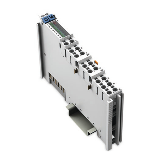
Pos: 18.4 /Serie 750 (WAGO-I/O-SYSTEM)/Gerätebeschreibung/Ansicht/Analogausgangsklemmen/Ansicht 750-0597 @ 25\mod_1453473238404_21.docx @ 199128 @ @ 1 Figure 1: View of Device Pos: 18.5 /Serie 750 (WAGO-I/O-SYSTEM)/Gerätebeschreibung/Ansicht/Ansicht Push-in CageClamp®_Legende mit LEDs @ 15\mod_1370852562803_21.docx @ 122213 @ @ 1 Table 4: Legend for Figure “View”... -
Page 18: Connectors
Do not place the I/O modules on the gold spring contacts in order to avoid soiling or scratching! Pos: 18.9.3 /Serie 750 (WAGO-I/O-SYSTEM)/Wichtige Erläuterungen/Sicherheits- und sonstige Hinweise/Achtung/Achtung: ESD - Auf gute Erdung der Umgebung achten! @ 7\mod_1266318538667_21.docx @ 50708 @ @ 1 Ensure that the environment is well grounded! The devices are equipped with electronic components that may be destroyed by electrostatic discharge. -
Page 19: Power Jumper Contacts/Field Supply
When configuring your system, ensure that this current is not exceeded. If exceeded, insert an additional supply module. Pos: 18.12.6 /Serie 750 (WAGO-I/O-SYSTEM)/Wichtige Erläuterungen/Sicherheits- und sonstige Hinweise/Hinweis/Hinweis: Potentialeinspeiseklemme für Erde einsetzen! (keine LK für Erde) @ 3\mod_1226499037468_21.docx @ 25023 @ @ 1 Manual... -
Page 20: Push-In Cage Clamp ® Connectors
Use a supply module when an earth potential is needed for the subsequent I/O modules. Pos: 18.13 /Dokumentation allgemein/Gliederungselemente/------Leerzeile------ @ 3\mod_1224662755687_0.docx @ 24460 @ @ 1 Pos: 18.14 /Serie 750 (WAGO-I/O-SYSTEM)/Gerätebeschreibung/Anschlüsse/Push-in CAGE CLAMP®-Anschlüsse - Überschrift 3 @ 15\mod_1370519905692_21.docx @ 122018 @ 3 @ 1 ® 3.2.3... -
Page 21: Table 6: Legend For The "Push-In Cage Clamp ® Connections" - 8-Channel
Common 0V Ground ground potential Pos: 18.16 /Serie 750 (WAGO-I/O-SYSTEM)/Wichtige Erläuterungen/Sicherheits- und sonstige Hinweise/Hinweis/Hinweis: Geschirmte Signalleitungen verwenden! @ 7\mod_1265723251019_21.docx @ 50140 @ @ 1 Use shielded signal lines! Only use shielded signal lines for analog signals and I/O modules which are equipped with shield clamps. -
Page 22: Display Elements
Pos: 18.18 /Alle Serien (Allgemeine Module)/Überschriften/Neue Überschriften/Ebene 2Anzeigeelemente - Überschrift 2 @ 4\mod_1240984390875_21.docx @ 31964 @ 2 @ 1 Display Elements Pos: 18.19 /Serie 750 (WAGO-I/O-SYSTEM)/Gerätebeschreibung/Anzeigeelemente/Analogausgangsklemmen/Anzeigeelemente 750-0597 @ 25\mod_1455615642607_21.docx @ 201629 @ @ 1 Figure 5: Display Elements Table 7: Legend for Figure “Display Elements”... -
Page 23: Operating Elements
Pos: 18.21 /Alle Serien (Allgemeine Module)/Überschriften/Neue Überschriften/Ebene 2Bedienelemente - Überschrift 2 @ 4\mod_1239191655456_21.docx @ 30439 @ 2 @ 1 Operating Elements Pos: 18.22 /Serie 750 (WAGO-I/O-SYSTEM)/Gerätebeschreibung/Bedienelemente/Bedienelemente Busklemme 750-xxxx nicht vorhanden @ 4\mod_1236322031125_21.docx @ 28063 @ @ 1 The I/O module 750-597 has no operating elements. -
Page 24: Technical Data
Pos: 18.26 /Alle Serien (Allgemeine Module)/Überschriften/Neue Überschriften/Ebene 2Technische Daten - Überschrift 2 @ 3\mod_1232967587687_21.docx @ 26924 @ 2 @ 1 Technical Data Pos: 18.27 /Serie 750 (WAGO-I/O-SYSTEM)/Gerätebeschreibung/Technische Daten/Analogausgangsklemmen/Technische Daten 750-0597 @ 25\mod_1453473491958_21.docx @ 199140 @ 3333 @ 1 3.6.1 Device Data Table 8: Technical Data —... -
Page 25: Outputs
Pos: 18.28.1 /Alle Serien (Allgemeine Module)/Überschriften/Neue Überschriften/Ebene 3Anschlusstechnik - Überschrift 3 @ 17\mod_1380123271324_21.docx @ 132788 @ 3 @ 1 3.6.5 Connection Type Pos: 18.28.2 /Serie 750 (WAGO-I/O-SYSTEM)/Gerätebeschreibung/Technische Daten/Anschlusstechnik/Technische Daten Verdrahtungsebene Push-in CC - 0,08 bis 1,5mm2(eindrg.) + 0,25 bis 1,5mm2(feindrg.) @ 19\mod_1400241224524_21.docx @ 153913 @ @ 1 Table 12: Technical Data ‒ Field Wiring ®... -
Page 26: Climatic Environmental Conditions
Pos: 18.34 /Alle Serien (Allgemeine Module)/Überschriften/Neue Überschriften/Ebene 2Normen und Richtlinien - Überschrift 2 @ 4\mod_1242804031875_21.docx @ 33646 @ 2 @ 1 Standards and Guidelines Pos: 18.35 /Serie 750 (WAGO-I/O-SYSTEM)/Gerätebeschreibung/Normen und Richtlinien/EMV-Normen Busklemme 750-xxxx, ohne Variantenangabe - Einleitung @ 4\mod_1242803944015_21.docx @ 33642 @ @ 1 750-597 I/O modules meet the following requirements on emission and immunity of interference: Pos: 18.36 /Alle Serien (Allgemeine Module)/Normen und Richtlinien/EMV-Normen - Standard/EMV CE-Störfestigkeit EN 61000-6-2 @ 4\mod_1242797655625_21.docx @ 33591 @ @ 1... -
Page 27: Process Image
Pos: 20 /Alle Serien (Allgemeine Module)/Überschriften/Neue Überschriften/Ebene 1Prozessabbild - Überschrift 1 @ 4\mod_1240983067828_21.docx @ 31942 @ 1 @ 1 Process Image Pos: 21 /Serie 750 (WAGO-I/O-SYSTEM)/Prozessabbild Klemmenbus/Hinweis: Prozessabbildmapping abhängig von FBK/PFC, ohne Status-/Controlbyte @ 6\mod_1256126797251_21.docx @ 43340 @ @ 1 Mapping of process data in the process image of fieldbus systems The representation of the process data of some I/O modules or their variants in the process image depends on the fieldbus coupler/controller used. -
Page 28: Overview
Presentation of control/status bytes a function of fieldbus coupler/controller! The I/O module always makes a complete process image incl. control/status bytes available to the fieldbus coupler/controller. The WAGO-I/O-CHECK startup tool accesses the startup process image. The fieldbus coupler/controller uses a different process image, in which display of control/status bytes can be supported, to stage cyclic process data via the fieldbus. -
Page 29: Status Bytes
Process Image WAGO-I/O-SYSTEM 750 750-597 8AO 0-10V/±10V DC Status Bytes The status byte for channel 1 displays the diagnoses “Undervoltage field supply” and “General Error”. Table 17: Status Byte CH1_S0 Status byte CH1_S0, Byte 0 Bit 7 Bit 6 Bit 5... -
Page 30: Process Data
Table of Contents WAGO-I/O-SYSTEM 750 750-597 8AO 0-10V/±10V DC Process Data 4.3.1 Overview of Signal Types The following table serves as an overview of all supported signal types. The following sections contain detailed information about the individual signal types. The information provided in the respective tables on the resolution of the voltage values and the raw value ranges yielded from this are based on manufacturer scaling with user scaling disabled. -
Page 31: Signal Type "+/- 10 V", Id1
Process Image WAGO-I/O-SYSTEM 750 750-597 8AO 0-10V/±10V DC '0000.0000.0000.0000' 0x0000 0x00 '0010.0000.0000.0000' 0x2000 8192 0x00 '0100.0000.0000.0000' 0x4000 16384 0x00 '0110.0000.0000.0000' 0x6000 24576 0x00 10.0 '0111.1111.1111.1111' 0x7FFF 32767 0x00 Undervoltage field supply 0x60 4.3.3 Signal Type “+/- 10 V”, ID1 4.3.3.1 Amount/Sign Format For the power supply with signal type “„+/- 10 V”, the numerical range of... -
Page 32: Two's Complement Representation
Table of Contents WAGO-I/O-SYSTEM 750 750-597 8AO 0-10V/±10V DC 4.3.3.2 Two's Complement Representation For the power supply with signal type “+/- 10 V”, the numerical range of 0x8000 … 0x7FFF is scaled to the output voltage range of −10 V … +10 V. The value is mapped at a process value resolution of 0.305 mV per 1 digit. -
Page 33: Mounting
The blade contacts are sharp-edged. Handle the I/O module carefully to prevent injury. Pos: 25.3 /Serie 750 (WAGO-I/O-SYSTEM)/Wichtige Erläuterungen/Sicherheits- und sonstige Hinweise/Achtung/Achtung: Busklemmen nur in vorgesehener Reihenfolge stecken! @ 6\mod_1256194177073_21.docx @ 43429 @ @ 1 Insert I/O modules only from the proper direction! All I/O modules feature grooves for power jumper contacts on the right side. -
Page 34: Inserting And Removing Devices
WAGO-I/O-SYSTEM 750 750-597 8AO 0-10V/±10V DC Pos: 25.6 /Serie 750 (WAGO-I/O-SYSTEM)/Montieren/Demontieren/Geräte einfügen und entfernen - Überschrift 2 @ 3\mod_1231768483250_21.docx @ 25950 @ 2 @ 1 Inserting and Removing Devices Pos: 25.7 /Alle Serien (Allgemeine Module)/Sicherheits- und sonstige Hinweise/Achtung/Achtung: Arbeiten an Geräten nur spannungsfrei durchführen! @ 6\mod_1256193963573_21.docx @ 43426 @ @ 1 Perform work on devices only if they are de-energized! Working on energized devices can damage them. -
Page 35: Removing The I/O Module
Mounting WAGO-I/O-SYSTEM 750 750-597 8AO 0-10V/±10V DC Pos: 25.10 /Serie 750 (WAGO-I/O-SYSTEM)/Montieren/Demontieren/Busklemme entfernen @ 4\mod_1239169375203_21.docx @ 30334 @ 3 @ 1 5.2.2 Removing the I/O Module Remove the I/O module from the assembly by pulling the release tab. Figure 9: Removing the I/O Module (Example) Electrical connections for data or power jumper contacts are disconnected when removing the I/O module. -
Page 36: Connect Devices
Pos: 27 /Alle Serien (Allgemeine Module)/Überschriften/Neue Überschriften/Ebene 1Geräte anschließen - Überschrift 1 @ 3\mod_1234172889468_21.docx @ 27460 @ 1 @ 1 Connect Devices Pos: 28 /Serie 750 (WAGO-I/O-SYSTEM)/Anschließen/Leiter an Push-in CAGE CLAMP® anschließen - Überschrift 2 und Text @ 6\mod_1258964749000_21.docx @ 44640 @ 2 @ 1 Connecting a Conductor to the Push-in CAGE ®... -
Page 37: Connection Example
Pos: 30 /Alle Serien (Allgemeine Module)/Überschriften/Neue Überschriften/Ebene 2Anschlussbeispiel - Überschrift 2 @ 4\mod_1242621672468_21.docx @ 33293 @ 2 @ 1 Connection Example Pos: 31 /Serie 750 (WAGO-I/O-SYSTEM)/Wichtige Erläuterungen/Sicherheits- und sonstige Hinweise/Hinweis/Hinweis: Geschirmte Signalleitungen verwenden! @ 7\mod_1265723251019_21.docx @ 50140 @ @ 1 Use shielded signal lines! Only use shielded signal lines for analog signals and I/O modules which are equipped with shield clamps. -
Page 38: Commissioning
Pos: 35 /Serie 750 (WAGO-I/O-SYSTEM)/In Betrieb nehmen/Parametrieren mit WAGO-I/O-CHECK/Parametrieren mit WAGO-I/O-CHECK - Überschrift 2 @ 7\mod_1268645151531_21.docx @ 52473 @ 2 @ 1 Parameterization with WAGO-I/O-CHECK Pos: 36 /Serie 750 (WAGO-I/O-SYSTEM)/In Betrieb nehmen/Parametrieren mit WAGO-I/O-CHECK/Konfigurieren und Parametrieren mit WAGO I/O-CHECK 750-0597 @ 25\mod_1453474641487_21.docx @ 199152 @ 3444566554555555444 @ 1 The WAGO-I/O-CHECK software from WAGO Kontakttechnik GmbH & Co. -
Page 39: Figure 12: Wago-I/O-Check User Interface
Right-click on the I/O module and then click the Settings menu item (see the figure below). Figure 12: WAGO-I/O-CHECK User Interface The parameterization dialog appears, which forms the basis for the following description. This forms the basis for the subsequent explanation. -
Page 40: Figure 13: Display Of Process Data
Table of Contents WAGO-I/O-SYSTEM 750 750-597 8AO 0-10V/±10V DC To display the process date for the configured 750-597 I/O module, proceed as follows: Click the I/O module and then the Process data button. Right-click on the I/O module and then click the Process data menu item (see figure). -
Page 41: Parameterization Dialog
Commissioning WAGO-I/O-SYSTEM 750 750-597 8AO 0-10V/±10V DC 7.1.1 Parameterization Dialog The parameterization dialog is divided into the following areas: Figure 14: Parameterization Dialog for the I/O Module 750-597 Title bar Horizontal tab menu Main menu Vertical tab menu Display range... -
Page 42: Title Bar
Table of Contents WAGO-I/O-SYSTEM 750 750-597 8AO 0-10V/±10V DC 7.1.1.1 Title Bar The title bar in the parameterization dialog contains the program icon, a window title and buttons for exiting, minimizing and maximizing the application window. Figure 15: Title Bar in the Parameterization Dialog... -
Page 43: Horizontal Tab Menu
Commissioning WAGO-I/O-SYSTEM 750 750-597 8AO 0-10V/±10V DC 7.1.1.3 Horizontal Tab Menu The horizontal tab menu contains the following tabs: Figure 16: Horizontal Tab Menu Click one of the tabs to display the respective selection options in the main menu. The individual tabs are explained in the following sections. -
Page 44: Open" Menu Item
“Open” Menu Item Only open parameter files created with WAGO-I/O-CHECK! Please note that only parameter files created with WAGO-I/O-CHECK can be opened. The parameter files have the extension *.ao. In this menu item you can open and load an existing parameter file. Proceed as follows: 1. -
Page 45: Save" Menu Item
Commissioning WAGO-I/O-SYSTEM 750 750-597 8AO 0-10V/±10V DC 7.1.1.3.1.2 “Save” Menu Item The calibration settings are not saved! Please note that the calibration settings cannot be saved in the parameter file. Note the memory range! Please note that only the settings are saved in the parameter file that you have... -
Page 46: 7.1.1.3.3 "Connection" Tab
Table of Contents WAGO-I/O-SYSTEM 750 750-597 8AO 0-10V/±10V DC The exact meaning of the individual selection options is described in the “Main Menu” section. 7.1.1.3.3 “Connection” Tab Click the Connection tab in the horizontal tab menu to display the following selection options in the main menu. - Page 47 Commissioning WAGO-I/O-SYSTEM 750 750-597 8AO 0-10V/±10V DC Click one of the menu items to call up the related parameterization options in the display area. The exact meaning of the individual selection options is described in the following sections. Manual Version 1.0.0...
-
Page 48: 7.1.1.4.1 "Module Settings" Menu Item
Table of Contents WAGO-I/O-SYSTEM 750 750-597 8AO 0-10V/±10V DC 7.1.1.4.1 “Module settings” Menu Item Save settings! Click the [Write] or [Write all button to write any settings you have made to the I/O module. Figure 23: Module settings Menu Item View... -
Page 49: 7.1.1.4.2 "Channel Settings" Menu Item
Commissioning WAGO-I/O-SYSTEM 750 750-597 8AO 0-10V/±10V DC 7.1.1.4.2 “Channel settings” Menu Item Save settings! Click the [Write] or [Write all button to write any settings you have made to the I/O module. Figure 24: Channel settings Menu Item View Table 26: Channel settings Menu Item... -
Page 50: 7.1.1.4.3 "Scaling" Menu Item
Table of Contents WAGO-I/O-SYSTEM 750 750-597 8AO 0-10V/±10V DC 7.1.1.4.3 “Scaling” Menu Item Save settings! Click the [Write] or [Write all button to write any settings you have made to the I/O module. Selecting the scaling method! If user scaling is enabled, enabling or disabling manufacturer scaling has no effect. -
Page 51: Table 27: Scaling Menu Item
Commissioning WAGO-I/O-SYSTEM 750 750-597 8AO 0-10V/±10V DC Table 27: Scaling Menu Item Option Description Channel x Manufacturer scaling is enabled (no scaling of Gain and Offset). Manufacturer scaling is disabled (no scaling of Gain and Offset). Enable manufacturer ... -
Page 52: 7.1.1.4.4 "Calibration" Menu Item
Table of Contents WAGO-I/O-SYSTEM 750 750-597 8AO 0-10V/±10V DC 7.1.1.4.4 “Calibration” Menu Item Save settings! Click the [Write] or [Write all button to write any settings you have made to the I/O module. Figure 26: Calibration Menu Item View Manual... -
Page 53: Table 28: Calibration Menu Item
Commissioning WAGO-I/O-SYSTEM 750 750-597 8AO 0-10V/±10V DC Table 28: Calibration Menu Item Option Description Enable factory configuration Factory calibration is enabled and user calibration is disabled. Enable Factory calibration is disabled and user calibration is enabled. factory configurati Gain The Gain value is specified by the manufacturer. -
Page 54: 7.1.1.4.5 "Process Value" Menu Item
Table of Contents WAGO-I/O-SYSTEM 750 750-597 8AO 0-10V/±10V DC 7.1.1.4.5 “Process Value” Menu Item In this area, an overview of all I/O module channels and the respective process value are displayed. Save settings! Click the [Write] or [Write all button to write any settings you have made to the I/O module. -
Page 55: 7.1.1.4.6 "Information" Menu Item
Commissioning WAGO-I/O-SYSTEM 750 750-597 8AO 0-10V/±10V DC 7.1.1.4.6 “Information” Menu Item This area provides an overview of the specifications for the I/O module used. You obtain information about the following points: • Article number • Description • Software version • Hardware version Figure 28: Information Menu Item View 7.1.1.5... -
Page 56: Status Messages
Table of Contents WAGO-I/O-SYSTEM 750 750-597 8AO 0-10V/±10V DC 7.1.1.6 Status Messages This area provides information about occurring undervoltages of the field supply. A requirement for displaying status message is that the checkbox for the “Enable diagnostic functions globally” function is activated in the Module Settings menu item. -
Page 57: Calibrating Process Values
Commissioning WAGO-I/O-SYSTEM 750 750-597 8AO 0-10V/±10V DC Pos: 38 /Serie 750 (WAGO-I/O-SYSTEM)/In Betrieb nehmen/Kalibrieren/Kalibrieren 750-0597 @ 25\mod_1453474855543_21.docx @ 199156 @ 23 @ 1 Calibrating Process Values Manufacturer calibration serves to compensate for tolerances in electrical components of the I/O module. User calibration allows you to compensate for the... -
Page 58: Example Of Determining Gain And Offset
= y1 – (m × x1) b = 1 V − (0.99 × 0.97 V) = 0.04 V 10. Enter the calculated gain value (“0.99”) in WAGO-I/O-CHECK. 11. Convert the result for the calibration offset based on the process value resolution: 0.04 V / 0.000305 V per digit = 131 digit... -
Page 59: Scaling Process Values
Commissioning WAGO-I/O-SYSTEM 750 750-597 8AO 0-10V/±10V DC Pos: 40 /Serie 750 (WAGO-I/O-SYSTEM)/In Betrieb nehmen/Skalieren/Skalieren 750-5xx @ 25\mod_1456491656124_21.docx @ 202878 @ 2 @ 1 Scaling Process Values User scaling allows you to scale the process value application specific with the following voltage ranges by means of parameterizing the Gain and Offset values: Signal type “+/- 10 V”: −11 V …... -
Page 60: Diagnostics
Pos: 42 /Alle Serien (Allgemeine Module)/Überschriften/Neue Überschriften/Ebene 1Diagnose - Überschrift 1 @ 4\mod_1240831069471_21.docx @ 31372 @ 1 @ 1 Diagnostics Pos: 43 /Serie 750 (WAGO-I/O-SYSTEM)/Diagnose/Busklemmen/Diagnose 750-0597 @ 25\mod_1453474929657_21.docx @ 199160 @ @ 1 The response of the I/O module if a diagnostic is present depends on the configuration. -
Page 61: Appendix
Pos: 45 /Alle Serien (Allgemeine Module)/Überschriften/Neue Überschriften/Ebene 1Anhang - Überschrift 1 @ 4\mod_1239874070437_21.docx @ 30560 @ 1 @ 1 Appendix Pos: 46 /Serie 750 (WAGO-I/O-SYSTEM)/In Betrieb nehmen/Parametrieren über GSD-Datei/Konfigurieren und Parametrieren per GSD-Datei bei PROFIBUS DP und PROFINET IO- Überschrift 2 @ 19\mod_1399559517054_21.docx @ 153249 @ 2 @ 1 Configuration and Parameterization using a GSD File with PROFIBUS DP and PROFINET IO Pos: 47 /Serie 750 (WAGO-I/O-SYSTEM)/In Betrieb nehmen/Parametrieren über GSD-Datei/Anhang: GSD-Dateien - Konfiguration + Parametrierung 8 AI 750-0597 @ 25\mod_1453475350821_21.docx @ 199164 @ 34434444 @ 1... -
Page 62: Parameterization 8 Ai 0-10 V, ±10 V Dc S.e
Table of Contents WAGO-I/O-SYSTEM 750 750-597 8AO 0-10V/±10V DC 9.1.2 Parameterization 8 AI 0-10 V, ±10 V DC S.E. The GSD file can be used to provide the I/O module on the PROFIBUS DP and PROFINET IO fieldbus coupler with all operating parameters. -
Page 63: Figure 33: Example Of The 750-370 Fieldbus Coupler Parameterization Dialog
Appendix WAGO-I/O-SYSTEM 750 750-597 8AO 0-10V/±10V DC Figure 33: Example of the 750-370 fieldbus coupler parameterization dialog part 2 Figure 34: Example of the 750-375(/025-000) and 750-377(/025-000) fieldbus coupler parameterization dialog part 1 Manual Version 1.0.0... -
Page 64: All Profibus Dp And Profinet Io Fieldbus Couplers
Table of Contents WAGO-I/O-SYSTEM 750 750-597 8AO 0-10V/±10V DC Figure 35: Example of the 750-375(/025-000) and 750-377(/025-000) fieldbus coupler parameterization dialog part 2 9.1.2.1 All PROFIBUS DP and PROFINET IO Fieldbus Couplers The following assignment applies to the parameters of the I/O module when using PROFIBUS DP and PROFINET IO fieldbus devices. -
Page 65: Profibus Dp Fieldbus Coupler 750-333(/0Xx-000), 750-833(/0Xx-000)
Appendix WAGO-I/O-SYSTEM 750 750-597 8AO 0-10V/±10V DC 9.1.2.2 PROFIBUS DP Fieldbus Coupler 750-333(/0xx-000), 750-833(/0xx-000) The aforementioned fieldbus couplers or controllers allow module-specific parameterization of diagnosis behavior as well as channel-specific parameterization of a substitute value. Table 38: General module / channel parameters... -
Page 66: Profinet Io Fieldbus Coupler 750-370
Table of Contents WAGO-I/O-SYSTEM 750 750-597 8AO 0-10V/±10V DC 9.1.2.3 PROFINET IO Fieldbus Coupler 750-370 The aforementioned fieldbus coupler allows module-specific parameterization of diagnosis and the substitute value behavior of the outputs as well as channel- specific parameterization of the process data representation and the output substitute value. -
Page 67: Profinet Io Fieldbus Coupler 750-375(/025-000), 750-377(/025-000)
Appendix WAGO-I/O-SYSTEM 750 750-597 8AO 0-10V/±10V DC 9.1.2.4 PROFINET IO Fieldbus Coupler 750-375(/025-000), 750-377(/025-000) The aforementioned fieldbus couplers allow module-specific parameterization of behavior at diagnosis. Table 40: General module / channel parameters Parameter Value Explanation Module diagnosis An undervoltage of the I/O module’s field side power supply... -
Page 68: List Of Figures
Figure 10: Connecting a Conductor to a Push-in CAGE CLAMP ...... 36 Figure 11: Connection Example – 2-Wire Connection ......... 37 Figure 12: WAGO-I/O-CHECK User Interface ............ 39 Figure 13: Display of Process Data ............... 40 Figure 14: Parameterization Dialog for the I/O Module 750-597 ......41 Figure 15: Title Bar in the Parameterization Dialog .......... -
Page 69: List Of Tables
WAGO-I/O-SYSTEM 750 List of Tables 750-597 8AO 0-10V/±10V DC Pos: 51 /Dokumentation allgemein/Verzeichnisse/Tabellenverzeichnis - Überschrift oG und Verzeichnis @ 3\mod_1219222958703_21.docx @ 21084 @ @ 1 List of Tables Table 1: Number Notation ..................9 Table 2: Font Conventions ..................9 Table 3: Compatibility List 750-597 .............. - Page 70 WAGO-I/O-SYSTEM 750 750-597 8AO 0-10V/±10V DC Pos: 54 /Dokumentation allgemein/Einband/Einband Handbuch - Rückseite 2015 @ 9\mod_1285229376516_21.docx @ 64944 @ @ 1 WAGO Kontakttechnik GmbH & Co. KG Postfach 2880 • D-32385 Minden Hansastraße 27 • D-32423 Minden Phone: 05 71/8 87 – 0 Fax: 05 71/8 87 –...
Need help?
Do you have a question about the I/O-SYSTEM 750 and is the answer not in the manual?
Questions and answers