WAGO I/O-SYSTEM 750 Manual
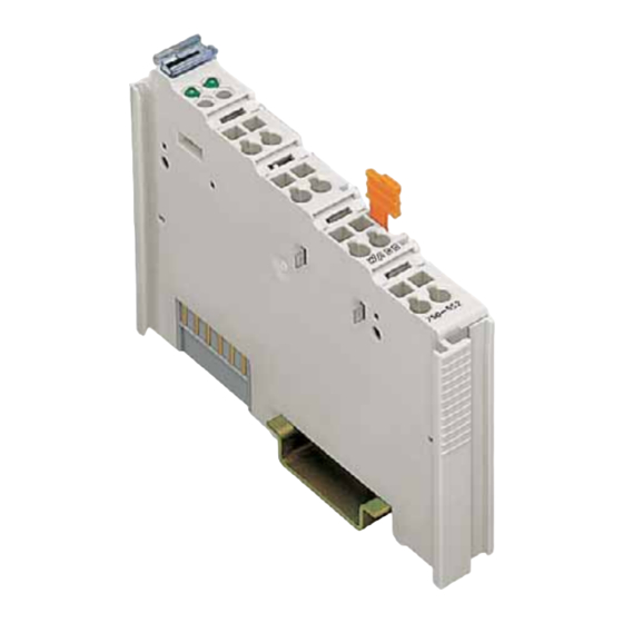
Fieldbus independent i/o modules 2 ao 0/+-10v dc 16 bit
Hide thumbs
Also See for I/O-SYSTEM 750:
- User manual ,
- Manual (450 pages) ,
- User's installation and configuration (335 pages)

Subscribe to Our Youtube Channel
Related Manuals for WAGO I/O-SYSTEM 750


Summary of Contents for WAGO I/O-SYSTEM 750
- Page 1 Fieldbus Independent I/O Modules 2 AO 0/+-10V DC 16 Bit 750-562 Manual Version 1.1.1...
- Page 2 • General Copyright 2009 by WAGO Kontakttechnik GmbH & Co. KG All rights reserved. WAGO Kontakttechnik GmbH & Co. KG Hansastraße 27 D-32423 Minden Phone.: +49 (0) 571/8 87 – 0 Fax: +49 (0) 571/8 87 – 1 69 E-Mail: info@wago.com...
-
Page 3: Table Of Contents
2.1.1.9.2.1 Configuration Concept ............20 2.1.1.9.2.2 Switching the Operating Mode..........20 2.1.1.9.2.3 Register Access and EEPROM Banks ........ 20 2.1.1.9.3 Parameterization via WAGO-I/O-CHECK......22 2.1.1.9.3.1 User Interface ..............22 2.1.1.9.4 Parameterization via GSD............31 2.1.1.10 Technical Data ................32 3 Use in Hazardous Environments ............. 34 Marking Configuration Examples ............ -
Page 4: Scope
1.1 Scope This manual describes the Analog Output Module 750-562 2 AO 0/+-10V DC 16 Bit of the modular WAGO-I/O-SYSTEM 750. Handling, assembly and start-up are described in the manual of the Fieldbus Coupler. Therefore this documentation is valid only in the connection with the appropriate manual. - Page 5 If this should happen, an additional supply module has to be used. The output module can be operated on all couplers/controllers (with the exception of the economy variants 750-320, -323, -324, and -327) of the WAGO-I/O-SYSTEM 750. WAGO-I/O-SYSTEM 750 I/O Modules...
-
Page 6: Connecting Elements
No group error ERROR Group error 2.1.1.5 Operating Elements The 750-562 analog output module has no operating elements. The configuration and the parameters can be changed via the higher-level controller or with the WAGO-I/O-CHECK configuration tool. WAGO-I/O-SYSTEM 750 I/O Modules... -
Page 7: Schematic Diagram
0 ... 10 V +AO 1 +AO 2 -10 ... +10 V +Sense AO 1 +Sense AO 2 100 nF +24 V -Sense AO 1 -Sense AO 2 Ground Ground 10 nF 750-562 Fig. 2.1.1-4: Schematic circuit diagram g056201e WAGO-I/O-SYSTEM 750 I/O Modules... -
Page 8: Process Image
65535 Data format 0 ... 65535 Manufacturer calibration, without user scaling Numeric value -10 ... +10 V, [U ] = V hexadecimal decimal -10.0 0000 -5.0 3FFF 16383 7FFF 32767 +5.0 BFFF 49151 +10.0 FFFF 65535 WAGO-I/O-SYSTEM 750 I/O Modules... - Page 9 Setting of the upper and lower limit value depending on the numeric format: In the +/- numeric ranges, the limit values must be re-calculated to a positive equivalent in the range from 0 ... 65535 (see table). 1. Example: twos complement WAGO-I/O-SYSTEM 750 I/O Modules...
- Page 10 839 is the amplification factor (gain, register 34). The offset (register 33) remains 0. If limit values should now be determined, these must be multiplied by 3.2767 and then re-calculated as in the first example to a numeric equivalent in the range from 0 ... 65535. WAGO-I/O-SYSTEM 750 I/O Modules...
-
Page 11: Function Description
Maximum value 16 bits Integer without leading sign 0 65535 16 bits Integer with leading sign -32768 +32767 15 bits Integer with leading sign bit -32767 +32767 (leading sign bit = 1) (leading sign bit = 0) WAGO-I/O-SYSTEM 750 I/O Modules... -
Page 12: Step 2 - Y
GainAS = 256, the resolution remains uninfluenced in the 16-bit wide numeric range. The value of 1/256 permits amplifications in the range from 0.0039 to 255,9960 and thus offers the user scaling a very high variation range. WAGO-I/O-SYSTEM 750 I/O Modules... -
Page 13: Step 3 - Y
Underrange limit value Overrange limit value If you would like to set the limits to defined analog output values, then these must be determined either like the calibration values in step 5 or calculated from these. WAGO-I/O-SYSTEM 750 I/O Modules... -
Page 14: Dac
With the activation of the user calibration, the analog output range can be selected freely taking into account the operating mode. In reality, the minimum and maximum possible analog output values lie a little below or above the named analog limits. WAGO-I/O-SYSTEM 750 I/O Modules... -
Page 15: Parameter Setting
The substitute value is placed on the output of the module after a system reset or a watchdog timer overflow (module has received no process data for 100 ms). The substitute value is selected via register 32, bit 9. WAGO-I/O-SYSTEM 750 I/O Modules... - Page 16 41 (UNR), only the corresponding bits are set in the status byte and the output value is kept to the limit value. Bit 8: Switch-on behavior 0: * Ready for operation in the configured operating mode Outputs are high-ohm WAGO-I/O-SYSTEM 750 I/O Modules...
- Page 17 The values of the time fluctuate by ±10ms. Bit 15 Bit 14 Bit 13 Switch-on delay 0 ms 100 ms 200 ms 300 ms * 500 ms 750 ms * Factory setting WAGO-I/O-SYSTEM 750 I/O Modules...
- Page 18 Function Memory Access Factory setting User calibration offset 0xXXXX 16 bit integer value with leading sign. The user calibration is active if bit 1 is not set in register 32. * R37 / 8192 + R36 WAGO-I/O-SYSTEM 750 I/O Modules...
- Page 19 (UNR_x) is set in the status byte. With activated overrun limit (register 32, bit 7), the value Y is limited to this limit value. If values are written above the limit value, then these are declined by the module. WAGO-I/O-SYSTEM 750 I/O Modules...
-
Page 20: Data Structures
If the access occurs via pure register communication, no response is generated; for parameter channel communication, the parameter channel error flag is set. The principal behavior of the module when writing and reading the configuration register is explained in the following descriptions. WAGO-I/O-SYSTEM 750 I/O Modules... - Page 21 MB ? Register communication Access method? Parameter channel communication Parameter channel Response Error flag = 1 suppress Placing old date Placing new date in register X in register X Fig. 2.1.1-6: Storage access g056206e WAGO-I/O-SYSTEM 750 I/O Modules...
-
Page 22: Parameterization Via Wago-I/O-Check
22 • 750-562 [2 AO 0/+-10V DC 16 Bit] Parameter Setting 2.1.1.9.3 Parameterization via WAGO-I/O-CHECK The module can be parameterized easily with the start-up tool WAGO-I/O- CHECK. 2.1.1.9.3.1 User Interface The user interface of the 2-channel output module parameterizing dialog is divided into the following areas. - Page 23 Remark: The actual I-parameters will be saved to this file. [Read] read out the current settings from the attached device. [Write] transfers the indicated settings into the attached device. [Help] shows the help for this window. WAGO-I/O-SYSTEM 750 I/O Modules...
- Page 24 Operation Mode, Number Format, Output etc., are made (see chapter 2.1.1.9.3.1.4.1, „Settings“). [Offset/Gain] opens a page for setting Offset/Gain (see chapter 2.1.1.9.3.1.4.2, „Offset/Gain“). [Process data] opens a page for setting the Process data (see chapter 2.1.1.9.3.1.4.3, „Process data “). WAGO-I/O-SYSTEM 750 I/O Modules...
- Page 25 In order to transmit the new values to the module, click the [Write] button. The change symbols disappear. 2.1.1.9.3.1.4.1 Settings The Settings page enables the setting of the general module parameters. Fig. 2.1.1-10: Settings WAGO-I/O-SYSTEM 750 I/O Modules...
- Page 26 RUN LED goes out after 100 ms Action at Timeout Output 0 V / 0 A* Behavior after I/O module timeout Keep last value Output high-impedance User power-on value Substitute value after I/O module timeout WAGO power-on value WAGO-I/O-SYSTEM 750 I/O Modules...
- Page 27 If in addition a numeric display in the (+/-) range is selected, the limit values must be converted into equivalent values for a positive numeric range. 2.1.1.9.3.1.4.2 Offset/Gain The Offset/Gain page enables the setting of the offset and amplification values of the user and manufacturer scalings. Fig. 2.1.1-11: Offset/Gain WAGO-I/O-SYSTEM 750 I/O Modules...
- Page 28 Offset 0 ... +65535 Setting of the offset of the manufacturer calibration Gain 0 ... +65535 Setting of the amplification of the manufacturer calibration * Factory setting WAGO-I/O-SYSTEM 750 I/O Modules...
- Page 29 Under "Process Value" the value can be set as follows: Menu item Description Input field [__] Input possibility for the process value. Buttons [HEX] displays the value in hexadecimal format. [DEZ] displays the value in decimal format. [Apply] brings the value to the output. WAGO-I/O-SYSTEM 750 I/O Modules...
- Page 30 5 V system voltage smaller 4.65 V. Overstepping Limit Values Upper Limit Underrange limit value is not undershot. Underrange limit value is undershot. Lower Limit Overrange limit value is not exceeded. Overrange limit value is exceeded. WAGO-I/O-SYSTEM 750 I/O Modules...
-
Page 31: Parameterization Via Gsd
If in addition a numeric display in the (+/-) range is selected, the limit values must be converted into equivalent values for a positive numeric range. WAGO-I/O-SYSTEM 750 I/O Modules... -
Page 32: Technical Data
Data width 2 x 16 Bit data 2 x 8 Bit control/status Dimensions B x H* x T 12 mm x 64 mm x 100 mm * from upper-edge of DIN 35 rail Weight approx. 55 g WAGO-I/O-SYSTEM 750 I/O Modules... - Page 33 ≤ +60 °C Additional information Detailed information about approval can be found in the document "Overview WAGO-I/O-SYSTEM 750 Approvals" on the ELECTRONIC Tools and Docs. This document is found in the CD-ROM ELECTRONICC Tools and Docs (Item No.: 0888-0412) or online: www.wago.com...
-
Page 34: Use In Hazardous Environments
Use in Hazardous Environments 3BAnalog Output Modules 3 Use in Hazardous Environments The WAGO-I/O-SYSTEM 750 (electrical equipment) is designed for use in Zone 2 hazardous areas. The following sections include both the general identification of components (devices) and the installation regulations to be observed. The individual subsections of the "Installation Regulations"... -
Page 35: Marking Configuration Examples
Approval body and/or number of the examination IECEx PTB 07.0064X certificate I M2 / II 3 GD Explosion protection group and Unit category Ex nA Type of ignition and extended identification Explosion protection group Temperature class WAGO-I/O-SYSTEM 750 I/O Modules... - Page 36 Figure 3: Side marking example for Ex i and IEC Ex i approved I/O modules according to CENELEC and IEC Figure 4: Text detail – Marking example for Ex i and IEC Ex i approved I/O modules according to CENELEC and IEC WAGO-I/O-SYSTEM 750 I/O Modules...
- Page 37 Device category: Zone 2 device (Zone 0 subunit) Explosion protection mark Type of protection: Non-sparking operating equipment [ia] Category of type of protection intrinsic safety: Even safe when two errors occur Explosion Group Temperature class: Max. surface temperature 135°C WAGO-I/O-SYSTEM 750 I/O Modules...
-
Page 38: Marking For America According To Nec 500
Table 3: Description of marking example for I/O modules according to NEC 500 Printing on Text Description CL 1 Explosion protection group (condition of use category) DIV 2 Area of application (zone) Grp. ABCD Explosion group (gas group) Optemp code T4 Temperature class WAGO-I/O-SYSTEM 750 I/O Modules... -
Page 39: Installation Regulations
NFPA 70 National Electrical Code Art. 500 Hazardous Locations ANSI/ISA-RP 12.6-1987 Recommended Practice C22.1 Canadian Electrical Code Notice the following points When using the WAGO-I/O SYSTEM 750 (electrical operation) with Ex approval, the following points are mandatory: WAGO-I/O-SYSTEM 750 I/O Modules... -
Page 40: Special Conditions For Safe Operation Of The Atex And Iec Ex (Acc. Demko 08 Atex 142851X And Iecex Ptb 07.0064)
3.2.1 Special Conditions for Safe Operation of the ATEX and IEC Ex (acc. DEMKO 08 ATEX 142851X and IECEx PTB 07.0064) The fieldbus-independent I/O modules of the WAGO-I/O-SYSTEM 750-.../...-... must be installed in an environment with degree of pollution 2 or better. In the final... -
Page 41: Special Conditions For Safe Use (Atex Certificate Tüv 07 Atex 554086 X)
554086 X) For use as Gc- or Dc-apparatus (in zone 2 or 22) the field bus independent I/O modules WAGO-I/O-SYSTEM 750-*** shall be erected in an enclosure that fulfils the requirements of the applicable standards (see the marking) EN 60079-0, EN 60079-11, EN 60079-15, EN 61241-0 and EN 61241-1. For use as... - Page 42 If the module is energized do not remove or replace the fuse. Do not separate when energized! Do not separate the module when energized! Separate only in a non-hazardous area! Separate the module only in a non-hazardous area! WAGO-I/O-SYSTEM 750 I/O Modules...
-
Page 43: Special Conditions For Safe Use (Iec-Ex Certificate Tun 09.0001
3.2.3 Special conditions for safe use (IEC-Ex Certificate TUN 09.0001 For use as Dc- or Gc-apparatus (in zone 2 or 22) the fieldbus independent I/O modules WAGO-I/O-SYSTEM 750-*** shall be erected in an enclosure that fulfils the requirements of the applicable standards (see the marking) IEC 60079-0, IEC 60079-11, IEC 60079-15, IEC 61241-0 and IEC 61241-1. - Page 44 If the module is energized do not remove or replace the fuse. Do not separate when energized! Do not separate the module when energized! Separate only in a non-hazardous area! Separate the module only in a non-hazardous area! WAGO-I/O-SYSTEM 750 I/O Modules...
-
Page 45: Ansi/Isa 12.12.01
Devices containing fuses must not be fitted into circuits subject to over loads! Devices containing fuses must not be fitted into circuits subject to over loads, e.g. motor circuits! WAGO-I/O-SYSTEM 750 I/O Modules... - Page 46 Proof of certification is available on request. Also take note of the information given on the module technical information sheet. The Instruction Manual, containing these special conditions for safe use, must be readily available to the user. WAGO-I/O-SYSTEM 750 I/O Modules...
- Page 47 Use in Hazardous Environments • 47 Installation Regulations...
- Page 48 WAGO Kontakttechnik GmbH & Co. KG Postfach 2880 • D-32385 Minden Hansastraße 27 • D-32423 Minden Telefon: 05 71/8 87 – 0 Telefax: 05 71/8 87 – 1 69 E-Mail: info@wago.com Internet: http://www.wago.com...
Need help?
Do you have a question about the I/O-SYSTEM 750 and is the answer not in the manual?
Questions and answers