WAGO 750 Manual
16do 24vdc 0.5 a, low-side switching 16-channel digital output module 24 vdc; low-side switching
Hide thumbs
Also See for 750:
- User manual ,
- Manual (450 pages) ,
- User's installation and configuration (335 pages)
Table of Contents
Advertisement
Quick Links
Manual
Pos : 2 /D okumentati on allgemein/Ei nband/Ei nband Fronts eite - H andbuc h; CI 2017; mit DocVariablen (Standar d) @ 28\mod_1486477502910_0.doc x @ 405388 @ @ 1
WAGO I/O System 750
750-1505
16DO 24VDC 0.5 A, low-side switching
16-Channel Digital Output Module 24 VDC;
Low-side switching
Version 1.1.0
Pos : 3 /Alle Serien (Allgemeine M odul e)/Rec htlic hes, Allgemei nes/Impressum für Standardhandbüc her - allg. Angaben, Ansc hriften, T elefonnummer n und E-Mail-Adres sen @ 3\mod_1219151118203_21.doc x @ 21060 @ @ 1
Public
Advertisement
Chapters
Table of Contents

Related Manuals for WAGO 750


Summary of Contents for WAGO 750
- Page 1 Manual Pos : 2 /D okumentati on allgemein/Ei nband/Ei nband Fronts eite - H andbuc h; CI 2017; mit DocVariablen (Standar d) @ 28\mod_1486477502910_0.doc x @ 405388 @ @ 1 WAGO I/O System 750 750-1505 16DO 24VDC 0.5 A, low-side switching 16-Channel Digital Output Module 24 VDC;...
- Page 2 We wish to point out that the software and hardware terms as well as the trademarks of companies used and/or mentioned in the present manual are generally protected by trademark or patent. WAGO is a registered trademark of WAGO Verwaltungsgesellschaft mbH. === Ende der Liste für T extmar ke Ei nband_vorne === Manual Version 1.1.0...
-
Page 3: Table Of Contents
Legal Bases .................... 9 2.1.1 Subject to Changes ................9 2.1.2 Personnel Qualifications ..............9 2.1.3 Use of the 750 Series in Compliance with Underlying Provisions ..9 2.1.4 Technical Condition of Specified Devices......... 10 2.1.4.1 Disposal ..................10 2.1.4.1.1 Electrical and Electronic Equipment ........ - Page 4 Table of Contents WAGO I/O System 750 750-1505 16DO 24VDC 0.5 A, low-side switching Using in Safety Related Applications ............ 34 Important Notes ..................35 Connecting the I/O Module to Safety Switching Devices or F I/O Modules ..................36 7.2.1 General Structure of a Potential Group ..........
-
Page 5: Notes About This Documentation
Pos : 10 /Serie 750 ( WAGO I/O SYSTEM)/Hi nweis e z ur D okumentati on (alte Struktur)/Gül tigkeits bereic h/Gültig kei tsbereic h D okumentati on I/O-Modul 750- xxxx, ohne Variantenangabe @ 14\mod_1358944037947_21.doc x @ 109346 @ @ 1... -
Page 6: Symbols
Notes about this Documentation WAGO I/O System 750 750-1505 16DO 24VDC 0.5 A, low-side switching Pos : 12.4 /All e Seri en ( Allgemei ne Module)/Ü bers chriften/Ebene 2/Symbol e - Ü berschrift 2 @ 13\mod_1351068042408_21.doc x @ 105270 @ 2 @ 1 Symbols Pos : 12.5.1 /All e Serien ( Allgemei ne Module)/Sicherheits- und sons tige Hi nweis e/Gefahr/Gefahr: _War nung vor Pers onenschäden allgemei n_ - Erläuter ung @ 13\mod_1343309450020_21.doc x @ 101029 @ @ 1... - Page 7 WAGO I/O System 750 Notes about this Documentation 750-1505 16DO 24VDC 0.5 A, low-side switching Additional Information: Refers to additional information which is not an integral part of this documentation (e.g., the Internet). Pos : 12.6 /Dokumentation allgemei n/Glieder ungs elemente/---Seitenwechs el--- @ 3\mod_1221108045078_0.doc x @ 21810 @ @ 1 Manual Version 1.1.0...
-
Page 8: Number Notation
WAGO I/O System 750 750-1505 16DO 24VDC 0.5 A, low-side switching Pos : 12.7 /All e Seri en ( Allgemei ne Module)/Ü bers chriften/Ebene 2/D arstellung der Z ahlens ys teme - Ü bers chrift 2 @ 23\mod_1435647128078_21.doc x @ 184811 @ 2 @ 1 Number Notation Pos : 12.8 /All e Seri en ( Allgemei ne Module)/R ec htliches , Allgemei nes /Zahlens ysteme @ 3\mod_1221059454015_21.doc x @ 21711 @ @ 1... -
Page 9: Important Notes
Thus, the existence of such rights cannot be excluded. Pos : 15.4 /Serie 750 (WAGO I/O SYSTEM)/Wic htige Erläuterungen (al te Str uktur)/Pers onalqualifi kation/Pers onalqualifi kation 750- xxxx - Ü bersc hrift 3 und Inhalt @ 3\mod_1224061208046_21.doc x @ 24063 @ 3 @ 1 2.1.2... -
Page 10: Technical Condition Of Specified Devices
The implementation of safety functions such as EMERGENCY STOP or safety door monitoring must only be performed by the F I/O modules within the modular WAGO I/O System 750. Only these safe F I/O modules ensure functional safety in accordance with the latest international standards. WAGO's interference-free output modules can be controlled by the safety function. -
Page 11: 2.1.4.1.2 Packaging
WAGO I/O System 750 Important Notes 750-1505 16DO 24VDC 0.5 A, low-side switching Environmentally friendly disposal benefits health and protects the environment from harmful substances in electrical and electronic equipment. • Observe national and local regulations for the disposal of electrical and electronic equipment. -
Page 12: Safety Advice (Precautions)
Pos : 15.15.1 /Serie 750 ( WAGO I/O SYST EM)/Wichtige Erläuter ung en (alte Struktur)/Sic her heits- und s onstige Hi nweis e/Ac htung/Ac htung: Ei nwandfrei e Kontakti erung z ur Tragsc hiene gewährl eisten! @ 34\mod_1550481407638_21.doc... - Page 13 WAGO I/O System 750 Important Notes 750-1505 16DO 24VDC 0.5 A, low-side switching Ensure proper contact with the DIN-rail! Proper electrical contact between the DIN-rail and device is necessary to maintain the EMC characteristics and function of the device. Pos : 15.15.2 /Alle Serien (Allgemeine M odul e)/Sic herheits- und s onstige Hinweise/Achtung/Ac htung: D efekte oder bes chädigte Ger äte aus tausc hen! @ 6\mod_1260180857358_21.doc x @ 46743 @ @ 1 Replace defective or damaged devices! Replace defective or damaged device/module (e.g., in the event of deformed...
- Page 14 Important Notes WAGO I/O System 750 750-1505 16DO 24VDC 0.5 A, low-side switching Avoid electrostatic discharge! The devices are equipped with electronic components that may be destroyed by electrostatic discharge when touched. Please observe the safety precautions against electrostatic discharge per DIN EN 61340-5-1/-3. When handling the devices, please ensure that environmental factors (personnel, work space and packaging) are properly grounded.
-
Page 15: Device Description
Pos : 18.8 /Serie 750 (WAGO I/O SYSTEM)/Ger ätebesc hrei bung (al te Str uktur)/Ei nleitung/I/O-Besc hrei bung/DO/I/O-Besc hrei bung 750- x5xx DO LSS / negati vs chaltend ( 0 V) @ 3\mod_1233817190023_21.doc x @ 27163 @ @ 1 The I/O module outputs provide negative switching. - Page 16 Pos : 18.13 /Serie 750 ( WAGO I/O SYST EM)/Wichtige Erläuter ung en (alte Struktur)/Sic her hei ts- und s onstige Hi nweise/Hinweis/Hinweis: Potential einspeisemodul für Erde ei nsetzen! ( kei ne LK für Erde) @ 3\mod_1226499037468_21.doc...
-
Page 17: View
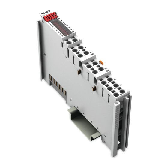
Pos : 20 /All e Seri en (Allgemei ne Module)/Ü berschriften/Ebene 2/Ansic ht - Ü berschrift 2 @ 4\mod_1240984217343_21.doc x @ 31958 @ 2 @ 1 View Pos : 21 /Serie 750 ( WAGO I/O SYSTEM)/Ger ätebesc hrei bung (al te Str uktur)/Ansic ht/D O/Ansicht 750-150x 16 DO C AGE C LAMP - Abb. @ 3\mod_1224766395937_21.doc x @ 24653 @ @ 1 Figure 1: View Pos : 22 /Serie 750 ( WAGO I/O SYSTEM)/Ger ätebesc hrei bung (al te Str uktur)/Ansic ht/Ansicht Pus h-in Cag eClamp®_Legende mit LEDs @ 15\mod_1370852562803_21.doc x @ 122213 @ @ 1... -
Page 18: Connectors
Pos : 26.3 /Serie 750 (WAGO I/O SYSTEM)/Wic htige Erläuterungen (al te Str uktur)/Sic herheits- und sonstige Hinweis e/Achtung/Ac htung: ESD - Auf Potenti alausgleic h der U mgebung achten! @ 32\mod_1539077262331_21.doc x @ 504433 @ @ 1... -
Page 19: Power Jumper Contacts/Field Supply
Power Jumper Contacts/Field Supply Pos : 29.1 /Serie 750 (WAGO I/O SYSTEM)/Wic htige Erläuterungen (al te Str uktur)/Sic herheits- und sonstige Hinweis e/Vorsic ht/Vorsic ht: Verletz ungsgefahr durc h sc harfkantige M ess er kontakte! @ 6\mod_1256193279401_21.doc x @ 43414 @ @ 1 Risk of injury due to sharp-edged blade contacts! The blade contacts are sharp-edged. - Page 20 Device Description WAGO I/O System 750 750-1505 16DO 24VDC 0.5 A, low-side switching Use supply modules for ground (earth)! The I/O module has no power jumper contacts for receiving and transmitting the earth potential. Use a supply module when an earth potential is needed for the subsequent I/O modules.
-
Page 21: Push-In Cage Clamp ® Connectors
750-1505 16DO 24VDC 0.5 A, low-side switching Pos : 31 /Serie 750 ( WAGO I/O SYSTEM)/Ger ätebesc hrei bung (al te Str uktur)/Ansc hlüsse/Pus h-in C AGE C LAM P®-Ansc hlüsse - Ü bersc hrift 3 @ 15\mod_1370519905692_21.doc x @ 122018 @ 3 @ 1 3.2.3... -
Page 22: Display Elements
Operating Elements Pos : 37 /Serie 750 ( WAGO I/O SYSTEM)/Ger ätebesc hrei bung (al te Str uktur)/Bedienel emente/Bedi enelemente I/O-Modul 75x- xxxx nicht vorhanden @ 4\mod_1236322031125_21.doc x @ 28063 @ @ 1 The I/O module 750-1505 has no operating elements. -
Page 23: Schematic Diagram
Pos : 40 /Serie 750 ( WAGO I/O SYSTEM)/Ger ätebesc hrei bung (al te Str uktur)/Schematische Sc hal tbil der/D O/Schematisc hes Schaltbild 750- 15xx 16 DO LSS C AGE C LAMP @ 3\mod_1233846401408_21.doc x @ 27348 @ @ 1... -
Page 24: Technical Data
Pos : 43.1 /Serie 750 (WAGO I/O SYSTEM)/Ger ätebesc hrei bung (al te Str uktur)/Technisc he Daten/VS (Variablensteuerung)/T echnisc he Daten Ger ät ( VS) ( nur Gerätedaten, kei ne Temperaturangaben) @ 20\mod_1413881815093_21.doc x @ 166173 @ 3 @ 1... -
Page 25: Connection Type
8 mm … 9 mm / 0.33 in Pos : 45.3 /Serie 750 (WAGO I/O SYSTEM)/Ger ätebesc hrei bung (al te Str uktur)/Technisc he Daten/Anschl uss tec hni k/T echnisc he D aten Leistungs kontakte (Mes ser/F eder) @ 19\mod_1400241643293_21.doc x @ 153921 @ @ 1 Table 12: Technical Data –... -
Page 26: Approvals
DOWNLOADS Documentation System Description. Pos : 50 /Serie 750 ( WAGO I/O SYSTEM)/Ger ätebesc hrei bung (al te Str uktur)/Z ulass ungen/Allgemein/Zul ass ungen I/O-Modul 750- xxxx Allgemei n, ohne Variantenang abe - Einl eitung @ 4\mod_1237460656921_21.doc x @ 28643 @ @ 1 The following approvals have been granted to 750-1505 I/O modules: Pos : 51.1 /All e Seri en ( Allgemei ne Module)/Z ulassungen/Standardz ulassungen/C E (Konformi täts kennz eichnung) @ 3\mod_1224494777421_21.doc x @ 24276 @ @ 1... -
Page 27: Standards And Guidelines
Pos : 59 /Serie 750 ( WAGO I/O SYSTEM)/Ger ätebesc hrei bung (al te Str uktur)/Nor men und Ric htlini en/EM V-Nor men I/O-Modul 750- xxxx, ohne Vari antenangabe - Einl eitung @ 4\mod_1242803944015_21.doc x @ 33642 @ @ 1... -
Page 28: Process Image
Pos : 65 /All e Seri en (Allgemei ne Module)/Ü berschriften/Ebene 1/Prozes sabbild - Ü berschrift 1 @ 4\mod_1240983067828_21.doc x @ 31942 @ 1 @ 1 Process Image Pos : 66 /Serie 750 ( WAGO I/O SYSTEM)/Proz ess abbild Lokalbus/DO/Proz ess abbil d 750- x5xx 16 DO @ 3\mod_1232537349671_21.doc x @ 26518 @ @ 1 Table 15: Output Bits 0 … 7... -
Page 29: Mounting
Pos : 69.2 /Serie 750 (WAGO I/O SYSTEM)/Wic htige Erläuterungen (al te Str uktur)/Sic herheits- und sonstige Hinweis e/Vorsic ht/Vorsic ht: Verletz ungsgefahr durc h sc harfkantige M ess er kontakte! @ 6\mod_1256193279401_21.doc x @ 43414 @ @ 1 Risk of injury due to sharp-edged blade contacts! The blade contacts are sharp-edged. -
Page 30: Mounting Sequence
I/O modules with fewer power contacts. Pos : 69.8 /Serie 750 (WAGO I/O SYSTEM)/Wic htige Erläuterungen (al te Str uktur)/Sic herheits- und sonstige Hinweis e/Achtung/Ac htung: I/O-Module nur in vorg esehener R eihenfolge stec ken! @ 6\mod_1256194177073_21.doc x @ 43429 @ @ 1 Insert I/O modules only from the proper direction! All I/O modules feature grooves for power jumper contacts on the right side. -
Page 31: Inserting And Removing Devices
750-1505 16DO 24VDC 0.5 A, low-side switching Inserting and Removing Devices Pos : 69.11 /Serie 750 ( WAGO I/O SYST EM)/Monti eren/D emonti eren/I/O-M odul einfügen ( neutr ales 3D) @ 35\mod_1561382037253_21.doc x @ 548869 @ 3 @ 1 5.2.1... -
Page 32: Removing The I/O Module
(if any) to the head station or to the preceding and, if applicable, following I/O module are established. Pos : 69.12 /Serie 750 ( WAGO I/O SYST EM)/Monti eren/D emonti eren/I/O-M odul entfernen (neutrales 3D) @ 35\mod_1561382848176_21.doc x @ 548874 @ 3 @ 1 5.2.2 Removing the I/O Module Remove the I/O module from the assembly by pulling the release tab. -
Page 33: Connect Devices
Connect Devices Pos : 72 /Serie 750 ( WAGO I/O SYSTEM)/Anschli eßen/Leiter an Pus h-in CAGE CLAMP® ansc hließ en - Ü bersc hrift 2 und T ext @ 6\mod_1258964749000_21.doc x @ 44640 @ 2 @ 1 Connecting a Conductor to the Push-in CAGE CLAMP ®... -
Page 34: Using In Safety Related Applications
750-1505 16DO 24VDC 0.5 A, low-side switching Pos : 74.1 /Serie 750 (WAGO I/O SYSTEM)/Eins atz in sicherheitsg erichteten Anwendung en/Ei nleitung - rüc kwir kungsfr eie I/O-Modul e: Ei nsatz i n Sicherheits anwendungen (Ü 1) @ 6\mod_1258973397992_21.doc x @ 44678 @ 1 @ 1 Using in Safety Related Applications The 750-1505 I/O module is suited for use in interference-free safety circuits. -
Page 35: Important Notes
Pos : 74.5 /Dokumentation allgemei n/Glieder ungs elemente/---Seitenwechs el--- @ 3\mod_1221108045078_0.doc x @ 21810 @ @ 1 Pos : 74.6 /Serie 750 (WAGO I/O SYSTEM)/Eins atz in sicherheitsg erichteten Anwendung en/Allgemeiner Aufbau ei ner Potentialgruppe - r üc kwir kungsfr eie I/O-M odul e @ 6\mod_1258972956853_21.doc x @ 44661 @ 23 @ 1 Manual Version 1.1.0... -
Page 36: Connecting The I/O Module To Safety Switching Devices Or F I/O Modules
(750-616) must be connected at the end of the potential group. Pos : 74.7 /Serie 750 (WAGO I/O SYSTEM)/Eins atz in sicherheitsg erichteten Anwendung en/Aufbau einer Potenti algruppe @ 6\mod_1259221280455_21.doc x @ 45332 @ @ 1 Figure 11: Potential Group for Safety Related Applications Pos : 75 /D okumentation allgemei n/Glieder ungs elemente/---Seitenwechs el--- @ 3\mod_1221108045078_0.doc x @ 21810 @ @ 1... -
Page 37: Examples Of Connection
750-1505 16DO 24VDC 0.5 A, low-side switching Pos : 76 /Serie 750 ( WAGO I/O SYSTEM)/Eins atz in sicherheitsg erichteten Anwendung en/Ansc hlus sbeispi ele/Ansc hlussbeis piel 16-Kanal-Digitalausgangs klemmen CC LSS i n Sicherheits anwendungen @ 9\mod_1281600868179_21.doc x @ 63288 @ 3 @ 1 Eins atz der rüc kwir kungsfrei en Digital ausg angs kl emme in Sic her heitsanwendungen... -
Page 38: Use In Hazardous Environments
Use in Hazardous Environments Pos : 78.2 /Serie 750 (WAGO I/O SYSTEM)/Eins atz in Ex- Ber eichen/Ei ns atz ber eic h Serie 750 @ 3\mod_1234272230203_21.doc x @ 27500 @ @ 1 The WAGO I/O System 750 (electrical equipment) is designed for use in Zone 2 hazardous areas and shall be used in accordance with the marking and installation regulations. -
Page 39: Marking Configuration Examples
Marking for Europe According to ATEX and IECEx Pos : 78.6 /Serie 750 (WAGO I/O SYSTEM)/Eins atz in Ex- Ber eichen/Beis piel bedruc kung ATEX und IEC Ex_TUEV07_2017 @ 14\mod_1360569228625_21.doc x @ 111294 @ @ 1 Figure 14: Marking Example According to ATEX and IECEx Figure 15: Text Detail –... -
Page 40: Table 17: Description Of Marking Example According To Atex And Iecex
Use in Hazardous Environments WAGO I/O System 750 750-1505 16DO 24VDC 0.5 A, low-side switching Table 17: Description of Marking Example According to ATEX and IECEx Marking Description TUEV 07 ATEX 554086 X Approving authority resp. certificate numbers IECEx TUN 09.0001 X... -
Page 41: Figure 16: Marking Example For Approved I/O Module Ex I According To
750-1505 16DO 24VDC 0.5 A, low-side switching Pos : 78.8 /Serie 750 (WAGO I/O SYSTEM)/Eins atz in Ex- Ber eichen/Beis piel bedruc kung ATEX und IEC Ex_TUEV12_Ex i_2017 @ 14\mod_1360569320118_21.doc x @ 111298 @ @ 1 Figure 16: Marking Example for Approved I/O Module Ex i According to ATEX and IECEx Figure 17: Text Detail –... -
Page 42: Table 18: Description Of Marking Example For Approved I/O Module Ex I According To Atex And Iecex
Use in Hazardous Environments WAGO I/O System 750 750-1505 16DO 24VDC 0.5 A, low-side switching Table 18: Description of Marking Example for Approved I/O Module Ex I According to ATEX and IECEx Marking Description TUEV 12 ATEX 106032 X Approving authority resp. certificate numbers... -
Page 43: Marking For The United States Of America (Nec) And Canada (Cec)
Figure 18: Marking Example According to NEC Pos : 78.11 /Serie 750 ( WAGO I/O SYST EM)/Ei ns atz i n Ex-Bereic hen/Beispi elbedruc kung und T extdetail N EC 500_2017 @ 14\mod_1360580302684_21.doc x @ 111353 @ @ 1 Figure 19: Text Detail – Marking Example According to NEC 500... -
Page 44: Figure 20: Text Detail - Marking Example For Approved I/O Module Ex I
750-1505 16DO 24VDC 0.5 A, low-side switching Pos : 78.13 /Serie 750 ( WAGO I/O SYST EM)/Ei ns atz i n Ex-Bereic hen/Beispi elbedruc kung und T extdetail N EC 505_2017 @ 29\mod_1497865583500_21.doc x @ 424739 @ @ 1 Figure 20: Text Detail – Marking Example for Approved I/O Module Ex i According to NEC 505... -
Page 45: Figure 22: Text Detail - Marking Example For Approved I/O Module Ex I
750-1505 16DO 24VDC 0.5 A, low-side switching Pos : 78.16 /Serie 750 ( WAGO I/O SYST EM)/Ei ns atz i n Ex-Bereic hen/Beispi elbedruc kung und T extdetail C EC_2017 @ 29\mod_1497865583297_21.doc x @ 424736 @ @ 1 Figure 22: Text Detail – Marking Example for Approved I/O Module Ex i According to CEC 18... -
Page 46: Installation Regulations
Special Notes including Explosion Protection Pos : 78.21.2 /Serie 750 ( WAGO I/O SYST EM)/Ei ns atz i n Ex-Bereic hen/Besonder e Hi nweis e einschli eßlich Explosionssc hutz _2017 @ 29\mod_1491556994025_21.doc x @ 415448 @ @ 1 The following warning notices are to be posted in the immediately proximity of the WAGO I/O System 750 (hereinafter “product”):... - Page 47 40 % due to transient faults (e.g., when powering the field supply). Product components intended for intrinsically safe applications may only be powered by 750-606 or 750-625/000-001 bus supply modules. Only field devices whose power supply corresponds to overvoltage category I or II may be connected to these components.
-
Page 48: Special Notes Regarding Ansi/Isa Ex
Special Notes Regarding ANSI/ISA Ex Pos : 78.21.5 /Serie 750 ( WAGO I/O SYST EM)/Ei ns atz i n Ex-Bereic hen/AN SI/ISA gemäß U L Fil e E198726_2017 @ 29\mod_1491557259544_21.doc x @ 415451 @ @ 1 For ANSI/ISA Ex acc. to UL File E198726, the following additional requirements apply: •... -
Page 49: List Of Figures
WAGO I/O System 750 List of Figures 750-1505 16DO 24VDC 0.5 A, low-side switching Pos : 80 /D okumentation allgemei n/Verz eic hniss e/Abbil dungs verz eic hnis - Übersc hrift oG und Verz eichnis @ 3\mod_1219222916765_21.doc x @ 21080 @ @ 1 List of Figures Figure 1: View ....................17... -
Page 50: List Of Tables
List of Tables WAGO I/O System 750 750-1505 16DO 24VDC 0.5 A, low-side switching Pos : 82 /D okumentation allgemei n/Verz eic hniss e/Tabell enverz eichnis - Übersc hrift oG und Verz eichnis @ 3\mod_1219222958703_21.doc x @ 21084 @ @ 1 List of Tables Table 1: Number Notation ................... - Page 51 WAGO I/O System 750 750-1505 16DO 24VDC 0.5 A, low-side switching Pos : 84 /D okumentation allgemei n/Einband/Einband - Leers eite für durc h 2 teilbare Seitenz ahl (Standarddruc k) @ 3\mod_1219230851078_0.doc x @ 21123 @ @ 1 Manual Version 1.1.0...
- Page 52 Pos : 85 /D okumentation allgemei n/Einband/Einband R üc ks eite - alle D okumente; CI 2017 @ 28\mod_1486477503580_21.doc x @ 405394 @ @ 1 WAGO Kontakttechnik GmbH & Co. KG Postfach 2880 • D - 32385 Minden Hansastraße 27 • D - 32423 Minden Phone: +49 571 887 –...
Need help?
Do you have a question about the 750 and is the answer not in the manual?
Questions and answers