Keithley SourceMeter 2400 User Manual
Sourcemeter 2400 series source measure unit
Hide thumbs
Also See for SourceMeter 2400:
- Service manual (137 pages) ,
- Quick start manual (46 pages) ,
- Quick results manual (53 pages)
Table of Contents
Advertisement
Quick Links
Download this manual
See also:
Service Manual
Advertisement
Table of Contents

Related Manuals for Keithley SourceMeter 2400


Summary of Contents for Keithley SourceMeter 2400
- Page 1 Artisan Technology Group is your source for quality new and certified-used/pre-owned equipment SERVICE CENTER REPAIRS WE BUY USED EQUIPMENT • FAST SHIPPING AND DELIVERY Experienced engineers and technicians on staff Sell your excess, underutilized, and idle used equipment at our full-service, in-house repair center We also offer credit for buy-backs and trade-ins •...
- Page 2 Model 2400 Series ® SourceMeter User's Manual A G R E A T E R M E A S U R E O F C O N F I D E N C E Artisan Technology Group - Quality Instrumentation ... Guaranteed | (888) 88-SOURCE | www.artisantg.com...
- Page 3 WARRANTY Keithley Instruments, Inc. warrants this product to be free from defects in material and workmanship for a period of 1 year from date of shipment. Keithley Instruments, Inc. warrants the following items for 90 days from the date of shipment: probes, cables, rechargeable batteries, diskettes, and documentation.
- Page 4 ® 2400 Series SourceMeter User’s Manual ©1998, Keithley Instruments, Inc. All rights reserved. Cleveland, Ohio, U.S.A. Seventh Printing, May 2002 Document Number: 2400S-900-01 Rev. G Artisan Technology Group - Quality Instrumentation ... Guaranteed | (888) 88-SOURCE | www.artisantg.com...
- Page 5 Revision F (Document Number 2400S-900-01) ............... June 2001 Revision G (Document Number 2400S-900-01)............... May 2002 All Keithley product names are trademarks or registered trademarks of Keithley Instruments, Inc. Other brand names are trademarks or registered trademarks of their respective holders.
- Page 6 Keithley products are designed for use with electrical signals that are rated Installation Category I and Installation Category II, as described in the International Electrotechnical Commission (IEC) Standard IEC 60664. Most measurement, control, and data I/O signals are Installation Category I and must not be directly connected to mains voltage or to voltage sources with high tran- sient over-voltages.
- Page 7 To maintain protection from electric shock and fire, replacement components in mains circuits, including the power transformer, test leads, and input jacks, must be purchased from Keithley Instruments. Standard fuses, with applicable national safety ap- provals, may be used if the rating and type are the same. Other components that are not safety related may be purchased from other suppliers as long as they are equivalent to the original component.
-
Page 8: Table Of Contents
Table of Contents Getting Started General information ..............Warranty information ............Contact information ............Manual addenda ..............Safety symbols and terms ........... Inspection ................Options and accessories ............General purpose probes ..........Low thermal probes ............. Cables and adapters ............. Rack mount kits ............ - Page 9 Menus ..................1-20 Main menu ................. 1-20 Rules to navigate menus ............ 1-24 Editing source and compliance values ......1-24 Toggling the source and measure display fields ....1-25 Disabling front panel display ..........1-25 Front panel control ............. 1-26 Remote command programming ........
- Page 10 NPLC caching ..............3-10 NPLC cache setup ............3-10 Typical NPLC cache test times ........3-11 V-source protection ............3-11 Front panel V-source protection ......... 3-12 Remote command V-source protection ...... 3-12 Source delay ..............3-12 Front panel source delay ..........3-13 Remote command source delay .........
- Page 11 Pulse Mode Operation (Model 2430 only) Overview ..................Pulse characteristics ..............Pulse width ................Signal measurement ............. Overhead time .............. Pulse width delay ............Output off-time ..............Reference and zero measurements ....... Overhead time .............. Pulse delay ..............Pulse duty cycle ..............Fast pulse output ..............
- Page 12 Pulse-measure considerations ..........5-16 Measurement speed ............5-16 Filter .................. 5-17 Auto range ................. 5-17 Concurrent measurements ..........5-17 Ohms source readback ............5-17 Toggle key ................. 5-17 Offset-compensated ohms ..........5-18 Source delay ..............5-18 Trigger delay ..............5-18 Input triggers ..............
- Page 13 I-Source operating boundaries .......... 6-21 Voltage compliance boundaries ........6-24 V-Source operating boundaries ......... 6-26 Current compliance boundaries ......... 6-28 Source I measure I and source V measure V ..... 6-30 Source readback accuracy .......... 6-30 Basic circuit configurations ............6-31 Source I ................
- Page 14 Filters ..................Response time considerations ........Front panel filter control ........... 7-10 Configuring filter ............7-10 CONFIGURE FILTERING menu ......7-10 Enabling filter ............7-10 Response time ............7-11 Remote filter programming ..........7-12 Filter commands ............7-12 Filter programming example ........7-13 Relative and Math Relative ..................
- Page 15 Buffer statistics ..............Minimum and maximum ..........Peak-to-peak ..............Average ................. Standard deviation ............Timestamp format ............... Timestamp accuracy ............Buffer considerations ............Using :TRACe commands to store data ....... Using :READ? to store data ......... Remote command data store ............Data store commands ............
- Page 16 Sweep branching program example ........10-27 Pulse Mode sweeps (Model 2430 only) ......... 10-32 Front panel Pulse Mode sweep procedure ...... 10-33 Remote Pulse Mode sweep operation ......10-34 Triggering Front panel trigger operation ............ 11-2 Front panel trigger model ..........11-2 Event detection ............
- Page 17 Pulse Mode triggering (Model 2430) ........11-30 Trigger models ..............11-30 Idle ................11-33 Source event detector ..........11-33 Pulse delay ............... 11-33 Source action ............11-33 Pulse width ............... 11-33 Measure action ............11-33 Output triggers ............11-34 Invalid trigger settings ............. 11-34 Front panel operation ..........
- Page 18 Configuring and performing limit tests ........12-19 Configuring limit tests ............. 12-19 Performing front panel limit tests ........12-21 Step 1: Configure test system........12-21 Step 2: Configure source-measure functions... 12-21 Step 3: Configure limit tests........12-22 Step 4: Turn output on.
- Page 19 Remote Operations Differences: remote vs. local operation ........14-2 Operation enhancements (remote operation) ....14-2 Math expressions ............14-2 Concurrent measurements .......... 14-2 Local-to-remote transition ..........14-2 Remote-to-local transition ..........14-3 Selecting an interface ............... 14-3 GPIB operation ................. 14-4 GPIB standards ..............
- Page 20 Response messages ............14-17 Sending a response message ........14-17 Multiple response messages ........14-17 Response message terminator (RMT) ..... 14-17 Message exchange protocol ..........14-17 RS-232 interface operation ............ 14-18 Sending and receiving data ..........14-18 Baud rate ................. 14-18 Data bits and parity ............
- Page 21 Queues ..................15-18 Output queue ..............15-18 Error queue ..............15-19 Programming example — read error queue ..... 15-20 Common Commands Command summary ..............16-2 Command reference ..............16-3 *IDN? — identification query ........... 16-3 *OPC — operation complete ..........16-3 *OPC? —...
- Page 22 Define math expression ........... 18-30 [:EXPRession] <form> or [:DEFine] <form> ..18-30 Enable and read math expression result ......18-33 :STATe <b> .............. 18-33 :DATA? ..............18-33 :LATest? ..............18-34 CALCulate2 ................18-34 Select input path .............. 18-34 FEED <name> ............18-34 Null feed reading .............
- Page 23 Read display ..............18-47 DATA? ..............18-47 Define :TEXT messages ..........18-48 DATA <a> ..............18-48 STATe <b> ..............18-48 FORMat subsystem ..............18-49 Data format ..............18-49 [:DATA] <type>[,length] .......... 18-49 Data elements ..............18-51 ELEMents <item list> ..........18-51 SOURce2 <name>...
- Page 24 Set compliance parameters ..........18-68 [:LEVel] <n> ............18-68 RSYNhronize <b> ........... 18-69 TRIPped? ..............18-70 Set measurement speed ........... 18-70 NPLCycles <n> ............18-70 Configure and control filter ..........18-71 TCONtrol <name> ........... 18-71 COUNt <n> ............. 18-71 [:STATe] <b> ............18-72 SOURce subsystem ..............
- Page 25 Configure list ..............18-91 CURRent <NRf list>..........18-91 VOLTage <NRf list> ..........18-91 APPend <NRf list> ..........18-92 POINts? ..............18-93 STARt <n> ............... 18-93 Configure memory sweep ..........18-93 SAVE <NRf> ............18-94 POINts <NRf> ............18-95 STARt <NRf> ............18-95 RECall <NRf>...
- Page 26 Error queue ..............18-105 [:NEXT]? ............... 18-105 CLEar ..............18-105 ENABle <list> ............18-105 DISable <list> ............18-106 SYSTem subsystem .............. 18-106 Default conditions ............18-106 PRESet ..............18-106 POSetup ..............18-106 Control remote sensing ..........18-107 RSENse <b> ............18-107 Select guard mode ............
- Page 27 Auto range change mode ..........18-117 RCMode <name> ........... 18-117 TRACe subsystem ..............18-117 Read and clear buffer ............. 18-117 DATA? ..............18-117 CLEar ..............18-118 Configure and control buffer ......... 18-118 FREE? ..............18-118 POINts <n> ............18-118 ACTual? ..............18-118 FEED <name>...
- Page 28 Data Flow Introduction ................FETCh? ................CALCulate[1]:DATA? ............CALCulate2:DATA? ............TRACe:DATA? ..............CALCulate3:DATA? ............IEEE-488 Bus Overview Introduction ................Bus description ................Bus lines ..................Data lines ................Bus management lines ............Handshake lines ..............Bus commands ................Uniline commands ............. Universal multiline commands ..........
- Page 29 Sweep limitations ............... Staircase and custom sweeps ........Source memory sweeps ..........Limit test sequence ............. Binning failure indications (grading mode) ..... F-10 Auto clear on, end binning ........F-10 Auto clear on, immediate binning ......F-10 Auto clear off, end binning ........F-10 Auto clear off, immediate binning ......
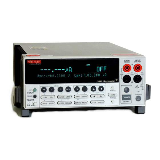
- Page 30 List of Illustrations Getting Started Figure 1-1 SourceMeter front panel ............Figure 1-2 SourceMeter rear panel ............Figure 1-3 Main menu tree ..............1-23 Connections Figure 2-1 Terminal voltage differentials (rear panel) ......Figure 2-2 Two-wire connections (local sense) ........Figure 2-3 Four-wire connections (remote sense) ........
- Page 31 Figure 6-13 V-Source limit lines .............. 6-28 Figure 6-14 V-Source operating examples ..........6-29 Figure 6-15 Source I ................6-31 Figure 6-16 Source V ................6-32 Figure 6-17 Measure only (V or I) ............6-33 Figure 6-18 High-impedance measurements ........... 6-36 Figure 6-19 In-circuit ohms measurements ..........
- Page 32 Figure 11-11 Operation model for triggering example ......11-27 Figure 11-12 Trigger model for remote trigger example ......11-29 Figure 11-13 2430 Pulse Mode trigger model (front panel operation) ..11-31 Figure 11-14 2430 Pulse Mode trigger model (remote operation) ..11-32 Limit Testing Figure 12-1...
- Page 33 SCPI Command Reference Figure 18-1 ASCII data format .............. 18-49 Figure 18-2 IEEE-754 single precision data format (32 data bits) ..18-50 Figure 18-3 Key-press codes ..............18-114 Data Flow Figure C-1 Data flow block diagram ............IEEE-488 Bus Overview Figure D-1 IEEE-488 bus configuration ..........
- Page 34 List of Tables Getting Started Table 1-1 Line frequency remote commands ........1-12 Table 1-2 Power line fuse ..............1-13 Table 1-3 Basic display commands ............1-15 Table 1-4 Factory default settings ............1-17 Table 1-5 Main menu ................1-20 Table 1-6 Measurement configuration menus ........
- Page 35 Range, Digits, Speed, and Filters Table 7-1 Range and digits commands ........... Table 7-2 Range and digits programming example ........ Table 7-3 Speed commands ..............Table 7-4 Filter commands ..............7-12 Table 7-5 Filter programming example ..........7-13 Relative and Math Table 8-1 Rel commands ................
- Page 36 Digital I/O Port, Safety Interlock, and Output Configuration Table 13-1 Digital output line settings ........... 13-5 Table 13-2 Output configuration commands ........13-11 Table 13-3 Output configuration programming example ..... 13-12 Remote Operations Table 14-1 General bus commands ............14-7 Table 14-2 RS-232 connector pinout ...........
- Page 37 Table 18-10 TRACe command summary ..........18-21 Table 18-11 TRIGger command summary ..........18-22 Status and Error Messages Table B-1 Status and error messages ............. IEEE-488 Bus Overview Table D-1 IEEE-488 bus command summary ........Table D-2 Hexadecimal and decimal command codes ......D-10 Table D-3 Typical addressed multiline command sequence ....
-
Page 38: Getting Started
Getting Started • General information — Covers general information that includes warranty infor- mation, contact information, safety symbols and terms, inspection, and available options and accessories. • Product overview — Summarizes the features of the SourceMeter. • Front and rear panel familiarization — Summarizes the controls and connectors of the instrument. -
Page 39: General Information
Contact information Worldwide phone numbers are listed at the front of this manual. If you have any questions, please contact your local Keithley representative or call one of our Application Engineers at 1-800-348-3735 (U.S. and Canada only). Manual addenda Any improvements or changes concerning the instrument or manual will be explained in an addendum included with the manual. -
Page 40: Inspection
If an additional manual is required, order the appropriate manual package (for example, 2400-901-00). The manual packages include a manual and any pertinent addenda. Options and accessories The following options and accessories are available from Keithley for use with the SourceMeter. General purpose probes Model 8605 high performance modular test leads —... -
Page 41: Low Thermal Probes
Model 5806 Kelvin clip lead set — Includes two Kelvin clip test leads (0.9m) with banana plug termination. Designed for instruments that measure four-terminal resistance. A set of replacement rubber bands is available (Keithley P/N GA-22). Model 8604 SMD probe set — Consists of two test leads (0.9m), each terminated with a surface mount device “grabber clip”... -
Page 42: Rack Mount Kits
® 2400 Series SourceMeter User’s Manual Getting Started Rack mount kits Model 4288-1 single fixed rack mount kit — Mounts a single SourceMeter in a standard 19-inch rack. Model 4288-2 side-by-side rack mount kit — Mounts two instruments (Models 182, 428, 486, 487, 2000, 2001, 2002, 2010, 2015, 2400, 2410, 2420, 2425, 2430, 2440, 6430, 6517, 7001) side-by-side in a standard 19-inch rack. - Page 43 Programming language and remote interfaces — The SourceMeter uses the SCPI programming language and two remote interface ports (IEEE-488/GPIB and RS-232C). • Trigger-Link interface to Keithley Series 7000 switching hardware. Artisan Technology Group - Quality Instrumentation ... Guaranteed | (888) 88-SOURCE | www.artisantg.com...
-
Page 44: Front And Rear Panel Familiarization
® 2400 Series SourceMeter User’s Manual Getting Started • Math expressions — Five built-in, up to five user-defined (bus only). • Reading and setup storage — Up to 2500 readings and seven setups (five user defaults, factory default, *RST default) can be stored and recalled. •... - Page 45 ® Getting Started 2400 Series SourceMeter User’s Manual Operation keys: EDIT Select source or compliance reading for editing. TOGGLE Toggle display positions of source and measure readings, or display V and I measurements. LOCAL Cancel remote operation. Enable/disable relative reading on present function. FILTER Display digital filter status for present function and toggle filter on/off.
-
Page 46: Rear Panel Summary
® 2400 Series SourceMeter User’s Manual Getting Started Rear panel summary The rear panel of the Model 2400 SourceMeter is shown in Figure 1-2. (The Models 2410, 2420, 2425, 2430, and 2440 are similar.) The following abbreviated information should be reviewed before operating the instrument. -
Page 47: Power-Up
® 1-10 Getting Started 2400 Series SourceMeter User’s Manual RS-232 connector: RS-232 Connector for RS-232 remote operation. Use a straight through (not null modem) DB-9 cable. GPIB connector: IEEE-488 Connector for GPIB remote operation. Use a shielded cable (Model INTERFACE 7007-1 or 7007-2). -
Page 48: Power-Up Sequence
® 2400 Series SourceMeter User’s Manual Getting Started 1-11 WARNING The power cord supplied with the SourceMeter contains a separate ground for use with grounded outlets. When proper connections are made, instrument chassis is connected to power line ground through the ground wire in the power cord. -
Page 49: Line Frequency Setting
® 1-12 Getting Started 2400 Series SourceMeter User’s Manual Line frequency setting At the factory, the SourceMeter is configured to sense the power line frequency and auto- matically select the frequency setting. If, however, the line power source is noisy, the SourceMeter may select the wrong setting on power-up. -
Page 50: Fuse Replacement
(Table 1-2). Push the fuse drawer back into the power module. Table 1-2 Power line fuse SourceMeter Fuse description Keithley part number 250V, 2.5A, 5 × 20mm 2400 and 2410 FU-72 250V, 3.15A, 5 × 20mm 2420, 2425, 2430, FU-106-3.15... -
Page 51: Display
® 1-14 Getting Started 2400 Series SourceMeter User’s Manual When the OUTPUT is turned OFF, the fan will either run at the low speed or stay at the speed it was at when the output was on (current range dependent). This speed option is set from the FAN selection of the GENERAL MENU. -
Page 52: Toggle Key
® 2400 Series SourceMeter User’s Manual Getting Started 1-15 TOGGLE key NOTE For the Model 2430 Pulse Mode, the TOGGLE key is disabled. With the output on, the TOGGLE key manipulates readings on the top display and on the bottom-left display. It has no effect on the compliance reading (Cmpl), which is located on the bottom right. -
Page 53: Front Panel Tests
® 1-16 Getting Started 2400 Series SourceMeter User’s Manual Front panel tests Use the TEST/FRONT-PANEL-TESTS selection of the main MENU to test various aspects of the front panel. Test selections include: • KEYS — Front panel keys are tested. Pressing a key displays a message that iden- tifies that key. -
Page 54: Power-On Configuration
® 2400 Series SourceMeter User’s Manual Getting Started 1-17 Power-on configuration You can also define which of the stored setups (factory default or user) the instrument assumes as the power-on configuration as follows: Press the MENU key, select SAVESETUP, then press ENTER. From the SAVESETUP menu, select GLOBAL, then press ENTER. - Page 55 ® 1-18 Getting Started 2400 Series SourceMeter User’s Manual Table 1-4 (continued) Factory default settings BENCH or GPIB Setting default Guard Cable Limit tests: DigOut: Size 4-bit Mode: Grading Binning control Immediate Auto clear: Disabled Delay 0.00001 sec Clear pattern H/W limits: Control Disabled...
- Page 56 ® 2400 Series SourceMeter User’s Manual Getting Started 1-19 Table 1-4 (continued) Factory default settings BENCH or GPIB Setting default Pulse Mode (2430 only): Pulse delay 0.0s Pulse width 0.20ms Ranging (measure): Auto range Enabled Value RS-232 No effect Sense mode 2-wire Source delay Auto-delay...
-
Page 57: Remote Setups
® 1-20 Getting Started 2400 Series SourceMeter User’s Manual Remote setups You can also save and recall setups via remote using the following SCPI commands: • Save and recall user setups using *SAV and *RCL (Section 16). • Restore GPIB defaults using *RST (Section 16). -
Page 58: Table 1-5 Main Menu
® 2400 Series SourceMeter User’s Manual Getting Started 1-21 Table 1-5 (continued) Main menu Menu item Description Parameters COMMUNICATION Select and configure remote interface. GPIB Select GPIB (IEEE-488 Bus), set primary address and 0 to 30 GPIB protocol. (Default: 24) RS-232 Select the RS-232 interface, set parameters. - Page 59 ® 1-22 Getting Started 2400 Series SourceMeter User’s Manual Table 1-5 (continued) Main menu Menu item Description Parameters A/D CTRL Control auto-zero, line frequency, NPLC caching. AUTO ZERO Control auto zero. DISABLE Disable auto zero. ENABLE Enable auto zero. ONCE Force auto zero immediate update.
-
Page 60: Main Menu Tree
® 2400 Series SourceMeter User’s Manual Getting Started 1-23 Figure 1-3 Main menu tree Press MENU key (Use to select item, then press ENTER). SAVESETUP GLOBAL SAVE RESTORE POWERON BENCH GPIB USER-SETUP-NUMBER RESET SOURCE MEMORY SAVE RESTORE COMMUNICATION GPIB RS-232 BAUD BITS PARITY... -
Page 61: Rules To Navigate Menus
® 1-24 Getting Started 2400 Series SourceMeter User’s Manual Rules to navigate menus Many source-measure functions and operations are configured from the front panel menus. Use the following rules to navigate through these configuration menus: NOTE Complete rules to edit source and compliance values are found in the Basic source-measure procedure in Section 3. -
Page 62: Toggling The Source And Measure Display Fields
® 2400 Series SourceMeter User’s Manual Getting Started 1-25 • SOURCE — increments or decrements the source or compliance value. Note that pressing either of these keys will automatically enable the source edit mode. • RANGE — selects the source or compliance range. •... -
Page 63: Front Panel Control
® 1-26 Getting Started 2400 Series SourceMeter User’s Manual Front panel control Front panel display circuitry is controlled from the DISABLE DISPLAY configuration menu, which is accessed by pressing CONFIG and then EDIT (or TOGGLE). To select an option (NOW, NEVER, SWEEP, or STORE), use the EDIT cursor keys to place the cursor on the desired option, then press ENTER. -
Page 64: Measurement Configuration Menus
® 2400 Series SourceMeter User’s Manual Getting Started 1-27 These various configuration menus are covered in detail in the pertinent sections of this manual. Table 1-6 Measurement configuration menus Configuration menu item Description CONFIG MEAS V Configure V measure. SENSE MODE 2-WIRE 2-wire mode (local sensing). -
Page 65: Source And Range Configuration Menus
® 1-28 Getting Started 2400 Series SourceMeter User’s Manual Table 1-7 Source and range configuration menus Configuration menu item Description CONFIG SOURCE V Configure V source. CONFIGURE V SOURCE PROTECTION Select voltage protection. SENSE MODE Select 2-wire or 4-wire sensing. 2-WIRE Local sensing. -
Page 66: Rel, Filter, And Limit Configuration Menus
® 2400 Series SourceMeter User’s Manual Getting Started 1-29 Table 1-7 (continued) Source and range configuration menus Configuration menu item Description CONFIG RANGE Program upper range limit. CONFIG RANGE Program lower range limit. CONFIG AUTO RANGE AUTO RANGE TYPE Select auto range type. SINGLE SRC MTR Select single SourceMeter operation. - Page 67 ® 1-30 Getting Started 2400 Series SourceMeter User’s Manual Table 1-8 (continued) Rel, filter, and limit configuration menus Configuration menu item Description CONFIG LIMIT Configure limit tests. CONFIGURE LIMITS MENU DIGOUT Program Digital I/O bit patterns for pass/fail. SIZE Select I/O number of bits. 3-BIT 3-bit size 4-BIT...
-
Page 68: Trigger Configuration Menu
® 2400 Series SourceMeter User’s Manual Getting Started 1-31 Table 1-9 Trigger configuration menu Configuration menu item Description CONFIG TRIG Configure triggering. CONFIGURE TRIGGER ARM LAYER Configure trigger model arm layer. ARM IN Select arm layer detection event. IMMEDIATE Immediate event detection. GPIB GPIB GET or *TRG. -
Page 69: Sweep, Digits, Speed, And Data Store Configuration Menus
® 1-32 Getting Started 2400 Series SourceMeter User’s Manual Table 1-10 Sweep, digits, speed, and data store configuration menus Configuration menu item Description CONFIG SWEEP Configure sweeps. CONFIGURE SWEEPS TYPE Select sweep type. STAIR Staircase sweep, program START, STOP, STEP. Log sweep, program START, STOP, # POINTS. -
Page 70: Output And Display Configuration Menus
® 2400 Series SourceMeter User’s Manual Getting Started 1-33 Table 1-11 Output and display configuration menus Configuration menu item Description CONFIG ON/OFF OUTPUT Configure output. CONFIGURE OUTPUT INTERLOCK Enable/disable interlock. DISABLE Disable interlock. ENABLE Enable interlock. OFF STATE Set up output off state. HIGH IMPEDANCE High impedance off state. -
Page 71: Sweep, Digits, Speed, And Output Configuration Menus
® 1-34 Getting Started 2400 Series SourceMeter User’s Manual Table 1-12 Sweep, digits, speed, and output configuration menus Configuration menu item Description CONFIG SWEEP Configure sweeps. CONFIGURE SWEEPS TYPE Select sweep type. STAIR Staircase sweep, program START, STOP, STEP. Log sweep, program START, STOP, # POINTS. CUSTOM Custom sweep, program parameters. - Page 72 ® 2400 Series SourceMeter User’s Manual Getting Started 1-35 Table 1-12 (continued) Sweep, digits, speed, and output configuration menus Configuration menu item Description CONFIG ON/OFF OUTPUT Configure output. CONFIGURE OUTPUT INTERLOCK Enable/disable interlock. DISABLE Disable interlock. ENABLE Enable interlock. OFF STATE Set up output off state.
- Page 73 ® 1-36 Getting Started 2400 Series SourceMeter User’s Manual Artisan Technology Group - Quality Instrumentation ... Guaranteed | (888) 88-SOURCE | www.artisantg.com...
- Page 74 Connections • Connection overview — Discusses front/rear terminal selection and using a test fixture interlock. Connections to DUT — Covers various methods for making connections to the • DUT, including 4-wire remote sensing, 2-wire local sensing, cable and ohms guard, as well as sense and guard selections. Artisan Technology Group - Quality Instrumentation ...
-
Page 75: Connection Overview
® Connections 2400 Series SourceMeter User’s Manual Connection overview WARNING To prevent electric shock, test connections must be configured such that the user cannot come in contact with conductors or any DUT that is in contact with the conductors. Safe installation requires proper shields, barriers, and grounding to prevent contact with conductors. -
Page 76: Remote Command Terminals Selection
® 2400 Series SourceMeter User’s Manual Connections Remote command terminals selection Use the :ROUTe:TERMinals (Section 18) command to select the front or rear panel termi- nals via remote. For example, send the following command to select the rear terminals: :ROUT:TERM REAR Conversely, send the following command to choose the front terminals: :ROUT:TERM FRON Test fixture interlock... -
Page 77: Figure
® Connections 2400 Series SourceMeter User’s Manual WARNING To prevent electric shock and/or damage to the SourceMeter, common mode voltage must be externally limited as follows: Models 2400 and 2410 — Limit common mode voltage to 250VDC, 1.05A maximum Models 2420 and 2425 — Limit common mode voltage to 250VDC, 3.15A maximum Model 2430 —... -
Page 78: Sensing Methods
® 2400 Series SourceMeter User’s Manual Connections NOTE To avoid redundancy, generic SourceMeter drawings will be used in this section. A generic drawing excludes the labeling for the terminal voltage differentials. Sensing methods Basic source-measure operations are performed using either 2-wire local sense connec- tions (Figure 2-2) or 4-wire remote sense connections... -
Page 79: Wire Remote Sensing
® Connections 2400 Series SourceMeter User’s Manual Figure 2-3 Four-wire connections (remote sense) 4-WIRE INPUT/ SENSE OUTPUT TERMINALS ON/OFF FRONT/ FRONT/ REAR REAR OUTPUT SourceMeter Front Panel Sense Selection: 4-wire NOTE Connections alone do not determine sense mode. For local sensing (Figure 2-2), 2-wire sensing must be selected from the SENSE MODE option of the... -
Page 80: Wire Local Sensing
® 2400 Series SourceMeter User’s Manual Connections WARNING When sourcing voltage in remote sense, make sure the sense leads are connected to the DUT. If a sense lead becomes disconnected, 0V will be sensed, and the SourceMeter will increase the output voltage (to possi- bly hazardous levels) to compensate. -
Page 81: Guarding Methods
® Connections 2400 Series SourceMeter User’s Manual Guarding methods Cable guard Use the high-impedance (cable) guard connection scheme shown in Figure 2-4 for the fol- lowing source-measure condition: • Test circuit impedance is >1GΩ. Note that cable guard must be selected for this connection scheme. See “Guard selection,”... -
Page 82: Ohms Guard
® 2400 Series SourceMeter User’s Manual Connections Ohms guard Use the guarded ohms connection schemes shown in Figure 2-5 for the following source- measure operation: • In-circuit resistance measurements on the DUT where other parasitic leakage devices are present. Note that ohms guard must be selected for this connection scheme. Ohms guard is not available for the 1A range (source or measure). -
Page 83: Guarded Ohms Measurements (Ohms Guard)
® 2-10 Connections 2400 Series SourceMeter User’s Manual Figure 2-5 Guarded ohms measurements (ohms guard) Resistor Network Resistor Network ≥1kΩ <1kΩ WARNING: WARNING: NO INTERNAL OPERATOR SERVICA NO INTERNAL OPERATOR SERVICA V, Ω V, Ω GUARD GUARD GUARD GUARD SENSE SENSE 4-WIRE INPUT/... -
Page 84: Sense And Guard Selections
® 2400 Series SourceMeter User’s Manual Connections 2-11 Sense and guard selections NOTE When sense or guard settings are changed, the OUTPUT will turn OFF. Sense selection When using the SENSE HI and LO terminals of the SourceMeter, 4-wire remote sensing must be selected. -
Page 85: Guard Selection
® 2-12 Connections 2400 Series SourceMeter User’s Manual Guard selection Cable guard is used for high-impedance guarding for cables (i.e., coax and triax) and test fixtures. Ohms guard provides a high-current guard output, which allows in-circuit guarded ohms measurements. On power-up, cable guard is selected. NOTE For 6-wire ohms measurements, use the guard output off mode. - Page 86 Basic Source-Measure Operation • Operation overview — Discusses source-measure capabilities, compliance limit, and fundamental source-measure configuration. Operation considerations — Covers warm-up, auto zero, V-source protection, and • source delay. • Basic source-measure procedure — Describes the basic procedure for setting up the SourceMeter for source-measure operations, including selecting the source function, output values, and compliance limits;...
-
Page 87: Basic Source-Measure Operation
® Basic Source-Measure Operation 2400 Series SourceMeter User’s Manual WARNING - CAUTION The SourceMeter uses a heat sink to dissipate heat. Also, the Models 2410, 2420, 2430, and 2440 have a cooling fan. The left side of the case is cut out to expose the black, finned heat sink. -
Page 88: Source-Measure Capabilities
® 2400 Series SourceMeter User’s Manual Basic Source-Measure Operation Operation overview Source-measure capabilities From the front panel, the SourceMeter can be configured to perform the following operations: • Source voltage — Display current and/or voltage measurement • Source current — Display voltage and/or current measurement •... -
Page 89: Table
® Basic Source-Measure Operation 2400 Series SourceMeter User’s Manual The full range of operation is explained in Section “Overheating protection” and “Oper- ating boundaries.” NOTE Output transient recovery — The time required for the V-source to recover to its original value (within 0.1% plus load regulation errors) after a step change in load current is <250µsec. - Page 90 ® 2400 Series SourceMeter User’s Manual Basic Source-Measure Operation Table 3-1 (continued) Source-measure capabilities 2420 2425/2430 Range Source Measure Range Source Measure 200mV ±210mV ±211mV 200mV ±210mV ±211mV ±2.1V ±2.11V ±2.1V ±2.11V ±21V ±21.1V ±21V ±21.1V ±63V ±63.3V 100V ±105V ±105.5V 10µA ±10.5µA...
-
Page 91: Table 3-2 Compliance Limits
® Basic Source-Measure Operation 2400 Series SourceMeter User’s Manual Compliance limit When sourcing voltage, the SourceMeter can be set to limit current. Conversely, when sourcing current, the SourceMeter can be set to limit voltage. The SourceMeter output will not exceed the compliance limit. Table 3-2 summarizes compliance limits according to range. -
Page 92: Compliance Commands
® 2400 Series SourceMeter User’s Manual Basic Source-Measure Operation Setting the compliance limit Front panel compliance limit Set the compliance limit from the front panel as follows: Select the desired source and measure functions using the MEAS and SOURCE keys. Press the EDIT key until the cursor flashes in the compliance (Compl:) display field. -
Page 93: Figure
® Basic Source-Measure Operation 2400 Series SourceMeter User’s Manual Basic circuit configurations The fundamental source-measure configurations for the SourceMeter are shown in Figure 3-1. When sourcing voltage, you can measure current or voltage (configuration A). When sourcing current, you can measure voltage or current (configuration B). Section “Basic circuit configurations,”... -
Page 94: Operation Considerations
® 2400 Series SourceMeter User’s Manual Basic Source-Measure Operation Operation considerations The following paragraphs discuss warm-up period, auto zero, V-source protection, and source delay. Warm-up The SourceMeter must be turned on and allowed to warm up for at least one hour to achieve rated accuracies. -
Page 95: Nplc Caching
® 3-10 Basic Source-Measure Operation 2400 Series SourceMeter User’s Manual NPLC caching NPLC caching speeds up source memory sweeps by caching A/D reference and zero val- ues. When NPLC caching is enabled (using the NPLC-CACHE/ENABLE menu selec- tion), the A/D reference and zero values will be saved for up to the 10 most recent voltage, current, and resistance measurement functions settings. -
Page 96: Typical Nplc Cache Test Times
® 2400 Series SourceMeter User’s Manual Basic Source-Measure Operation 3-11 Typical NPLC cache test times Typically, NPLC caching will decrease source memory sweep times by a factor of three. The table below shows typical averaged times for a test consisting of 10 sweeps of four source memory locations with NPLC values for successive memory locations set to 10, 1, 0.1, and 0.01 respectively. -
Page 97: Front Panel V-Source Protection
® 3-12 Basic Source-Measure Operation 2400 Series SourceMeter User’s Manual WARNING Even with the voltage protection limit set to the lowest value, NEVER touch anything connected to the terminals of the SourceMeter when the OUTPUT is ON. Always assume that a hazardous voltage (>30V rms) is present when the OUTPUT is ON. -
Page 98: Table 3-4 Auto Source Delay
® 2400 Series SourceMeter User’s Manual Basic Source-Measure Operation 3-13 Table 3-4 Auto source delay 2400 2410 2420 2425/2430 2440 Auto delay Auto delay I-range I-range I-range I-range I-range (Source V) (Source I) 1µA 1µA 10µA 10µA 10µA 3msec 3msec 10µA 10µA 100µA... -
Page 99: Basic Source-Measure Procedure
® 3-14 Basic Source-Measure Operation 2400 Series SourceMeter User’s Manual Basic source-measure procedure Output control Use the ON/OFF OUTPUT key to turn the SourceMeter output on or off for basic source- measure situations. You can also control the output off state (high impedance, normal, zero, or guard) and program the instrument for auto output off operation. - Page 100 ® 2400 Series SourceMeter User’s Manual Basic Source-Measure Operation 3-15 Note that compliance can also be determined by the measurement range. Depending on which value is lower, compliance occurs at the programmed value (real compliance) or at the maximum compliance value for the present fixed measurement range (range compli- ance).
-
Page 101: Step 3: Select Measurement Function And Range
® 3-16 Basic Source-Measure Operation 2400 Series SourceMeter User’s Manual NOTE To clear the source value to 0V or 0A, press the MENU key while in the edit source field. • Value adjust — To adjust the value, use the EDIT cursor keys to place the cur- sor at the appropriate position, and use the SOURCE keys to incre- ment or decrement the value. -
Page 102: Step 4: Turn Output On
® 2400 Series SourceMeter User’s Manual Basic Source-Measure Operation 3-17 NOTE 2400 — With the 200V V-Source range selected, the highest current measure- ment range is 100mA. With the 1A I-Source range selected, the highest voltage measurement range is 20V. 2410 —... -
Page 103: Basic Source-Measure Commands
® 3-18 Basic Source-Measure Operation 2400 Series SourceMeter User’s Manual Step 6: Turn output off. When finished, turn the output off by pressing the ON/OFF OUTPUT key. The OUTPUT indicator light will turn off. Remote command source-measure procedure Basic source-measurement procedures can also be performed via remote by sending appropriate commands in the right sequence. -
Page 104: Basic Source-Measure Programming Example
® 2400 Series SourceMeter User’s Manual Basic Source-Measure Operation 3-19 Source-measure programming example Table 3-6 summarizes the command sequence for a basic source-measure procedure. Note that the steps correspond to those listed previously in “Front panel source-measure proce- dure.” These commands set up the SourceMeter as follows: •... -
Page 105: Figure
® 3-20 Basic Source-Measure Operation 2400 Series SourceMeter User’s Manual Measure only Front panel measure only In addition to being used for conventional source-measure operations, the SourceMeter can also be used to measure only voltage or current. Perform the following steps to use the SourceMeter to measure voltage or current: Select source-measure functions. -
Page 106: Measure Only Programming Example
® 2400 Series SourceMeter User’s Manual Basic Source-Measure Operation 3-21 Remote command measure only Table 3-7 summarizes the basic command sequence for measure only. The steps outlined correspond to those in the “Front panel measure only” sequence above. These commands set up the SourceMeter for measure only voltage measurements up to 20V as follows: •... -
Page 107: Sink Operation
Rechargeable Alkaline Lead Acid If you are working with a battery type that is not listed here, please contact your local Keithley representative or call one of our Applica- tions Engineers at 1-800-348-3735 (U.S and Canada only) to obtain technical assistance. - Page 108 ® 2400 Series SourceMeter User’s Manual Basic Source-Measure Operation 3-23 Do not attempt to charge or discharge batteries exceeding the current or voltage requirements listed below: Model 2400: 21V @ 1.05A or 210V @ 105mA Model 2410: 21V @ 1.05A or 1100V @ 21mA Model 2420: 21V @ 3.15A or 63V @ 1.05A Model 2425: 21V @ 3.15A or 105V @ 1.05A Model 2430: 105V @ 1.05A or 105V @ 10.5A (pulse mode)
-
Page 109: Sink Programming Example
® 3-24 Basic Source-Measure Operation 2400 Series SourceMeter User’s Manual CAUTION If using the I-Source to charge and/or discharge batteries, the following precautions must be observed. Failure to observe these precautions could result in damage to the SourceMeter that is not covered by the warranty. -
Page 110: Ohms Measurements
Ohms Measurements • Ohms configuration menu — Outlines the ohms configuration menu that allows you to set up various ohms measurement aspects. Ohms measurement methods — Discusses auto and manual ohms measurement • methods and how to select them. • Ohms sensing —... -
Page 111: Figure
® Ohms Measurements 2400 Series SourceMeter User’s Manual Ohms configuration menu NOTE For the Model 2430 Pulse Mode, offset-compensated ohms cannot be enabled from the ohms configuration menu. However, offset-compensated ohms is avail- able as a math function (Section “Math operations”). -
Page 112: Table
® 2400 Series SourceMeter User’s Manual Ohms Measurements Ohms measurement methods NOTE For the Model 2430, the following ohms measurement procedures assume that the DC Mode of operation is selected (“Vsrc” or “Isrc” displayed in the source field). If in the Pulse Mode (“Vpls” or “Ipls” displayed), you can select the DC Mode by pressing CONFIG V or I, selecting the SHAPE menu item, and then selecting DC. -
Page 113: Selecting Ohms Measurement Method
® Ohms Measurements 2400 Series SourceMeter User’s Manual Selecting ohms measurement method On power-up, auto ohms is the default method for the ohms function. Perform the follow- ing steps to check and/or change the ohms measurement method: Press CONFIG and then Ω to display the ohms configuration menu. Using the EDIT keys, place the cursor (flashing menu item) on SOURCE and press ENTER. -
Page 114: Manual Ohms Measurements
® 2400 Series SourceMeter User’s Manual Ohms Measurements Select measurement range. Use the RANGE keys to select a range appropriate for the expected ohms reading, or use autorange by pressing AUTO. When using manual ranging, select- ing the most sensitive (lowest) range provides the best accuracy. Autorange auto- matically goes to the most sensitive range. - Page 115 ® Ohms Measurements 2400 Series SourceMeter User’s Manual NOTE Use the V-Source for manual ohms measurements when high-speed settling is required (i.e., production testing). Select measurement range. Using the RANGE keys, select the lowest possible fixed range or use AUTO range. Note that if sourcing current, you will be setting the voltage measurement range.
-
Page 116: Ohms Sensing
® 2400 Series SourceMeter User’s Manual Ohms Measurements Ohms sensing Ohms measurements can be made using either 2-wire or 4-wire sensing. (See Section 2 information on connections and sensing methods.) Note that resistance measurement accuracy specifications are based on using 4-wire sensing. The 2-wire sensing method has the advantage of requiring only two test leads. -
Page 117: Sense Selection
® Ohms Measurements 2400 Series SourceMeter User’s Manual Figure 4-3 4-wire resistance sensing SourceMeter Test Current (I) Input/Output HI LEAD Sense Current (pA) LEAD 4-wire Sense HI Lead Resistance Resistances Under Test 4-wire Sense LO LEAD Input/Output LO LEAD = Current sourced by SourceMeter = Voltage measured by SourceMeter = Voltage across resistor Because sense current is negligible,... -
Page 118: Offset-Compensated Ohms
® 2400 Series SourceMeter User’s Manual Ohms Measurements Offset-compensated ohms NOTE For the Model 2430, the following offset-compensated ohms method is not valid in the Pulse Mode. However, offset compensated ohms is available as a math function (Section “Math operations”). The presence of thermal EMFs (V ) can adversely affect low-resistance measurement accuracy. -
Page 119: Offset-Compensated Ohms Procedure
® 4-10 Ohms Measurements 2400 Series SourceMeter User’s Manual Offset-compensated ohms procedure NOTE The following procedure assumes that the desired ohms measurement method (auto or manual) is already selected and the SourceMeter is connected to the DUT as explained in Section 2. -
Page 120: Ohms Source Readback
® 2400 Series SourceMeter User’s Manual Ohms Measurements 4-11 Ohms source readback NOTE For the Model 2430 Pulse Mode, ohms source readback cannot be enabled. With ohms source readback enabled, the instrument measures the actual source value instead of the programmed value used for ohms measurements and then uses that mea- sured value for reading calculations. -
Page 121: Remote Commands For Basic Ohms Measurements
® 4-12 Ohms Measurements 2400 Series SourceMeter User’s Manual Press EXIT to return to normal display. Press MEAS then Ω to select the ohms measurement function. Select the appropriate measurement range, or use autoranging if desired. Turn on the output by pressing the ON/OFF OUTPUT key. Take readings from the display. -
Page 122: Auto Ohms Programming Example
® 2400 Series SourceMeter User’s Manual Ohms Measurements 4-13 Ohms programming example Table 4-3 summarizes the command sequence for a typical auto ohms measurement. These commands set up the SourceMeter as follows: • Ohms mode and range: auto, 20kΩ • Offset compensation: off •... - Page 123 ® 4-14 Ohms Measurements 2400 Series SourceMeter User’s Manual Artisan Technology Group - Quality Instrumentation ... Guaranteed | (888) 88-SOURCE | www.artisantg.com...
-
Page 124: Pulse Mode Operation (Model 2430 Only)
Pulse Mode Operation (Model 2430 only) • Overview — Provides a summary of Pulse Mode operation. • Pulse characteristics — Describes the timing characteristics that make up the pulse width and output off-time of the pulse period. Explains how to achieve the fastest pulse output. -
Page 125: Figure
® Pulse Mode Operation (Model 2430 only) 2400 Series SourceMeter User’s Manual Overview NOTE The Pulse Mode is only available for the Model 2430. The documentation in this section does not apply to the Models 2400, 2410, 2425, and 2440. While in the Pulse Mode, the Model 2430 can output one or more pulses. -
Page 126: Pulse Characteristics
® 2400 Series SourceMeter User’s Manual Pulse Mode Operation (Model 2430 only) Pulse characteristics NOTE For the purpose of discussion, positive polarity pulses are shown in the follow- ing illustrations. Keep in mind that the Model 2430 can output negative pulses. As shown in Figure 5-1, a pulse period consists of an output on-time (pulse width) and an... -
Page 127: Pulse Width
® Pulse Mode Operation (Model 2430 only) 2400 Series SourceMeter User’s Manual Pulse width The pulse width can be set from 0.15msec to 5.00msec. However, depending on how the SourceMeter is configured, the pulse width setting may not be achievable. For example, if it takes 1.667msec to perform the signal measurement, the minimum pulse width that can be achieved is 1.75msec (1.667msec signal measurement plus 80µsec overhead). -
Page 128: Pulse Width Delay
® 2400 Series SourceMeter User’s Manual Pulse Mode Operation (Model 2430 only) Pulse width delay When the pulse width setting is greater than the sum of the signal measurement and over- head times, a delay is used to achieve the desired pulse width. The pulse width delay can be calculated as follows: Pulse Width Delay = PW - Sig Meas - 80µsec Where: PW is the pulse width setting... -
Page 129: Pulse Delay
® Pulse Mode Operation (Model 2430 only) 2400 Series SourceMeter User’s Manual Pulse delay The pulse delay (PD) is set by the user. It can be set from 0 to 9999.999sec. Pulse duty cycle Duty Cycle is the percentage of time during the pulse period that the output is on. It is cal- culated as follows: Duty Cycle = Pulse Width / (Pulse Width + Off-time) For example, if the pulse width is 1msec and the off-time is 9msec, the duty cycle is calcu-... -
Page 130: Auto Zero
® 2400 Series SourceMeter User’s Manual Pulse Mode Operation (Model 2430 only) Auto zero The output off-time can be reduced by disabling auto zero. With auto zero disabled, only the signal is measured. As shown in Figure 5-3, the reference and zero measurements (which normally are part of the off-time) are not performed. -
Page 131: Pulse-Only
® Pulse Mode Operation (Model 2430 only) 2400 Series SourceMeter User’s Manual Pulse-only The fastest pulses are achieved by disabling measurements altogether. With the signal not measured, as shown in Figure 5-4, the pulse width can be as short as the 150µsec over- head. -
Page 132: Pulse Energy Limitations (10A Range)
® 2400 Series SourceMeter User’s Manual Pulse Mode Operation (Model 2430 only) Pulse energy limitations (10A range) Energy for pulses are provided by an internal bank of capacitors. Each pulse consumes energy from the capacitors. After a pulse is generated, the capacitors begin to recharge. The next pulse will occur at the configured time as long as the capacitors have had enough time to recharge. -
Page 133: Pulse Mode Configuration
® 5-10 Pulse Mode Operation (Model 2430 only) 2400 Series SourceMeter User’s Manual Pulse Mode configuration Front panel Pulse Mode configuration Select Pulse Mode, and set pulse width and pulse delay Press CONFIG then SOURCE V or I. Select SHAPE from the displayed choices, then press ENTER. Select PULSE from the displayed choices, then press ENTER. -
Page 134: Disable/Enable Auto Zero
® 2400 Series SourceMeter User’s Manual Pulse Mode Operation (Model 2430 only) 5-11 For continuous pulse output, select INFINITE, press ENTER and proceed to step 6. Otherwise, select FINITE, press ENTER and proceed to the next step to set the arm count. Enter the desired arm count value and press ENTER. -
Page 135: Basic Pulse Mode Operation
® 5-12 Pulse Mode Operation (Model 2430 only) 2400 Series SourceMeter User’s Manual Basic Pulse Mode operation NOTE The following procedure assumes that the Model 2430 is already connected to the DUT as explained in Section WARNING Hazardous voltages (>30V rms) can appear on the selected INPUT/ OUTPUT LO terminal when performing fast pulse operations. -
Page 136: Step 4: Select Source
® 2400 Series SourceMeter User’s Manual Pulse Mode Operation (Model 2430 only) 5-13 Step 4: Select source. Press SOURCE V to source voltage pulses or press SOURCE I to source current pulses. The presently programmed pulse value (Vpls or Ipls) and compliance level (Cmpl) are displayed. -
Page 137: Step 7: Turn Output On
® 5-14 Pulse Mode Operation (Model 2430 only) 2400 Series SourceMeter User’s Manual Step 7: Turn output on. Turn the output on by pressing the TRIG key or the ON/OFF OUTPUT key. The OUTPUT indicator will be on whenever a pulse is being sourced. During each pulse off-time, the output will be off (indicator off). -
Page 138: Table
® 2400 Series SourceMeter User’s Manual Pulse Mode Operation (Model 2430 only) 5-15 Remote command pulse-measure operation Basic pulse commands Table 5-1 summarizes the commands to perform pulse-measure operations. See Section 18 for more information on using these commands. Table 5-1 Basic pulse-measure commands Command Description... -
Page 139: Table
® 5-16 Pulse Mode Operation (Model 2430 only) 2400 Series SourceMeter User’s Manual Pulse-measure programming example Table 5-2 summarizes the command sequence to output and measure pulses. Note that the steps correspond to those listed in the “Front panel pulse-measure procedure,” page 5-12. -
Page 140: Filter
® 2400 Series SourceMeter User’s Manual Pulse Mode Operation (Model 2430 only) 5-17 Filter Filtering cannot be used while the Model 2430 is in the Pulse Mode. You can configure the filter, but you cannot enable it. Pressing the FILTER key displays the “Invalid in Pulse Mode!”... -
Page 141: Offset-Compensated Ohms
® 5-18 Pulse Mode Operation (Model 2430 only) 2400 Series SourceMeter User’s Manual Offset-compensated ohms From the front panel there are two methods to perform offset-compensated ohms measure- ments. For one method, which is enabled from the CONFIG OHMS menu, the 2-point measurement process is performed at a user-set source level, and at 0V or 0A. -
Page 142: Input Triggers
® 2400 Series SourceMeter User’s Manual Pulse Mode Operation (Model 2430 only) 5-19 Input triggers In the DC Mode, you can enable the source, delay and/or measure input event detectors. Section 11 for details on triggering. In the Pulse Mode, only the source detector is used. You can enable the delay and measure detectors, but they will be ignored. -
Page 143: Turning Source On
® 5-20 Pulse Mode Operation (Model 2430 only) 2400 Series SourceMeter User’s Manual Turning source on For remote Pulse Mode operation, an :INITiate command is used to start the pulse output process. The :READ? command will send :INITiate to start the pulse process, and it will also acquire the pulse readings. -
Page 144: Source-Measure Concepts
Source-Measure Concepts • Compliance limit — Discusses compliance limit including real and range compli- ances, maximum compliance values, and how to determine compliance limit. Overheating protection — Provides information on preventing SourceMeter over- • heating, including power equations. • Source-delay-measure cycle — Describes the various phases of the source-delay- measure cycle as well as sweep waveforms. - Page 145 ® Source-Measure Concepts 2400 Series SourceMeter User’s Manual Compliance limit When sourcing voltage, the SourceMeter can be set to limit current. Conversely, when sourcing current, the SourceMeter can be set to limit voltage. The SourceMeter output will not exceed the compliance limit. 2400 —...
-
Page 146: Table 6-1 Compliance Limits
® 2400 Series SourceMeter User’s Manual Source-Measure Concepts Maximum compliance values The maximum compliance values for the measurement ranges are summarized in Table 6-1. Table 6-1 Compliance limits 2400 2410 2420 Maximum Maximum Maximum Measure compliance Measure compliance Measure compliance range value range... -
Page 147: Compliance Examples
® Source-Measure Concepts 2400 Series SourceMeter User’s Manual Compliance examples When the SourceMeter goes into real compliance, the Cmpl label for the compliance dis- play will flash. When the SourceMeter goes into range compliance, the units label (“mA”) will flash instead. For the following examples, labels in boldface type indicate that they are flashing. -
Page 148: Table 6-2 Compliance Examples
® 2400 Series SourceMeter User’s Manual Source-Measure Concepts NOTE When in compliance, the source output may exceed the programmed value in order to maintain the compliance limit. Determining compliance limit The relationships to determine which compliance is in effect are summarized as follows: •... -
Page 149: Overheating Protection
After turning the SourceMeter back on, verify that the cooling fan is running. If the failure message persists, contact Keithley to facilitate repairs. Leaving the SourceMeter on with the failure message dis- played may result in damage to the unit. -
Page 150: Power Equations To Avoid Shutdown
® 2400 Series SourceMeter User’s Manual Source-Measure Concepts Above 30˚C, for both source and sink operation, the SourceMeter will not overheat if the high power range(s) is not used. For the Models 2400 and 2410, the high power range is 1A. -
Page 151: Model 2410 Sourcemeter
® Source-Measure Concepts 2400 Series SourceMeter User’s Manual Model 2410 SourceMeter When using the 1A range, you can use the two equations below to determine if the SourceMeter will overheat. Both of the equations must be true to ensure that the SourceMeter will not overheat. -
Page 152: Models 2425 And 2430 Sourcemeters
® 2400 Series SourceMeter User’s Manual Source-Measure Concepts Models 2425 and 2430 SourceMeters There are two equations for each of the high power ranges (20V, 3A and 100V, 1A). Both of the equations for the selected voltage range must be true to ensure that the SourceMeter will not overheat. -
Page 153: Source-Delay-Measure Cycle
® 6-10 Source-Measure Concepts 2400 Series SourceMeter User’s Manual Source-delay-measure cycle In addition to static source and/or measure operation, SourceMeter operation can consist of a series of source-delay-measure (SDM) cycles (Figure 6-1). During each SDM cycle, the following occurs: Set the source output level. Wait for the source delay. -
Page 154: Figure
® 2400 Series SourceMeter User’s Manual Source-Measure Concepts 6-11 The manually set delay (up to 9999.999 sec) is available to compensate for longer settling required by external circuitry. The more capacitance seen at the output, the more settling time is required for the source. The actual delay period needed can be calculated or deter- mined by trial and error. -
Page 155: Sweep Waveforms
® 6-12 Source-Measure Concepts 2400 Series SourceMeter User’s Manual Sweep waveforms There are four basic sweep types to select from: linear staircase, logarithmic staircase, custom, and source memory. Three of the sweeps are shown in Figure 6-3. The linear stair- case sweep goes from the start level to the stop level in equal linear steps. - Page 156 ® 2400 Series SourceMeter User’s Manual Source-Measure Concepts 6-13 Figure 6-3 Three basic sweep waveform types Stop Start Bias A. Linear Staircase Sweep Stop Logarithmic scale shown for staircase steps. Start Bias B. Logarithmic Staircase Sweep Last Point First Point Bias C.
-
Page 157: Operating Boundaries
® 6-14 Source-Measure Concepts 2400 Series SourceMeter User’s Manual Operating boundaries Source or sink Depending on how it is programmed and what is connected to the output (load or source), the SourceMeter can operate in any of the four quadrants. The four quadrants of operation for the SourceMeter models are shown in Figure 6-4 through... -
Page 158: Model 2400 Sourcemeter
® 2400 Series SourceMeter User’s Manual Source-Measure Concepts 6-15 Model 2400 SourceMeter The general operating boundaries for the Model 2400 are shown in Figure 6-4. In this drawing, the 1A, 20V and 100mA, 200V magnitudes are nominal values. The actual max- imum output magnitudes of the SourceMeter are 1.05A, 21V and 105mA, 210V. -
Page 159: Model 2410 Sourcemeter
® 6-16 Source-Measure Concepts 2400 Series SourceMeter User’s Manual Model 2410 SourceMeter The general operating boundaries for the Model 2410 are shown in Figure 6-5. In this drawing, the 1A, 20V and 20mA, 1kV magnitudes are nominal values. The actual maxi- mum output magnitudes of the SourceMeter are 1.05A, 21V and 21mA, 1.1kV. -
Page 160: Model 2420 Sourcemeter
® 2400 Series SourceMeter User’s Manual Source-Measure Concepts 6-17 Model 2420 SourceMeter The general operating boundaries for the Model 2420 are shown in Figure 6-6. In this drawing, the 3A, 20V and 1A, 60V magnitudes are nominal values. The actual maximum output magnitudes of the SourceMeter are 3.15A, 21V and 1.05A, 63V. -
Page 161: Models 2425 And 2430 Sourcemeters
® 6-18 Source-Measure Concepts 2400 Series SourceMeter User’s Manual Models 2425 and 2430 SourceMeters The general operating boundaries for the Models 2425 and 2430 are shown in Figure 6-7. The boundaries for the Model 2425 and Model 2430 DC Mode are shown in Figure 6-7A, and the boundaries for the Model 2430 Pulse Mode are shown in... - Page 162 ® 2400 Series SourceMeter User’s Manual Source-Measure Concepts 6-19 Figure 6-7 ≤ 30°C) Model 2425/2430 operating boundaries (T (IV) Source Sink 0.5A –V -100V -20V 100V -0.5A (III) (II) Source Sink = 100% Duty Cycle –I = ≤ 60% Duty Cycle A.
-
Page 163: Model 2440 Sourcemeter
® 6-20 Source-Measure Concepts 2400 Series SourceMeter User’s Manual Model 2440 SourceMeter The general operating boundaries for the Model 2440 are shown in Figure 6-8. In this drawing, the 5A, 10V and 1A, 40V magnitudes are nominal values. The actual maximum output magnitudes of the SourceMeter are 5.25A, 10.5V and 1.05A, 42V. -
Page 164: I-Source Operating Boundaries
® 2400 Series SourceMeter User’s Manual Source-Measure Concepts 6-21 I-Source operating boundaries Figure 6-9 Figure 6-10 show the operating boundaries for the I-Source. Only the first quadrant of operation is covered. Operation in the other three quadrants is similar. 2400 — Figure 6-9A shows the output characteristics for the Model 2400 I-Source. - Page 165 ® 6-22 Source-Measure Concepts 2400 Series SourceMeter User’s Manual Figure 6-9 I-Source output characteristics Limit Limit 210V 1100V Source Source 105mA 1.05A 21mA 1.05A A. Model 2400 B. Model 2410 Limit Limit Model 2430 Pulse Mode 105V DC Mode Source Source 1.05A 3.15A 10.5A...
- Page 166 ® 2400 Series SourceMeter User’s Manual Source-Measure Concepts 6-23 Figure 6-10 shows the limit lines for the I-Source. The current source limit line represents the maximum source value possible for the presently selected current source range. For example, if on the 100mA current source range, the current source limit line is at 105mA. The voltage compliance limit line represents the actual compliance that is in effect.
-
Page 167: Voltage Compliance Boundaries
® 6-24 Source-Measure Concepts 2400 Series SourceMeter User’s Manual Voltage compliance boundaries Where within the boundaries the SourceMeter operates depends on the load (DUT) that is connected to its output. Figure 6-11 shows operation examples for resistive loads that are 200Ω... - Page 168 ® 2400 Series SourceMeter User’s Manual Source-Measure Concepts 6-25 Figure 6-11 I-Source operating examples Voltage Limit Load Line V-Meter Operating (V M ) Point Current Source Load Line I-Source (I 100mA · R = (100mA) (200Ω) = 20V A. Normal I-Source Operation Voltage Limit Load Line Operating...
-
Page 169: V-Source Operating Boundaries
® 6-26 Source-Measure Concepts 2400 Series SourceMeter User’s Manual V-Source operating boundaries Figure 6-12 Figure 6-13 show the operating boundaries for the V-Source. Only the first quadrant of operation is covered. Operation in the other three quadrants is similar. 2400 — Figure 6-12A shows the output characteristics for the Model 2400 V-Source. - Page 170 ® 2400 Series SourceMeter User’s Manual Source-Measure Concepts 6-27 Figure 6-12 V-Source output characteristics Limit I Limit I 1.05A 1.05A 105mA 21mA Source V Source V 210V 1100V A. Model 2400 B. Model 2410 Limit I Limit I Model 2430 10.5A Pulse Mode 3.15A...
-
Page 171: Figure 6-13 V-Source Limit Lines
® 6-28 Source-Measure Concepts 2400 Series SourceMeter User’s Manual Figure 6-13 shows the limit lines for the V-Source. The voltage source limit line represents the maximum source value possible for the presently selected voltage source range. For example, if on the 20V source range, the voltage source limit line is at 21V. The current compliance limit line represents the actual compliance in effect. -
Page 172: Figure 6-14 V-Source Operating Examples
® 2400 Series SourceMeter User’s Manual Source-Measure Concepts 6-29 Figure 6-14 V-Source operating examples Current Limit Load Line 50mA I-Meter Operating Point 25mA Voltage Source Load Line V-Source (V = 50V/2kΩ = 25mA A. Normal V-source operation Current Limit Operating Load Line Point 50mA... -
Page 173: Source I Measure I And Source V Measure V
® 6-30 Source-Measure Concepts 2400 Series SourceMeter User’s Manual Source I measure I and source V measure V The SourceMeter can measure the function it is sourcing. When sourcing a voltage, you can measure voltage. Conversely, if you are sourcing current, you can measure the output current. -
Page 174: Figure 6-15 Source I
® 2400 Series SourceMeter User’s Manual Source-Measure Concepts 6-31 Basic circuit configurations Source I When configured to source current (I-Source) as shown in Figure 6-15, the SourceMeter functions as a high-impedance current source with voltage limit capability and can mea- sure current (I-Meter) or voltage (V-Meter). -
Page 175: Source V
® 6-32 Source-Measure Concepts 2400 Series SourceMeter User’s Manual Source V When configured to source voltage (V-Source) as shown in Figure 6-16, the SourceMeter functions as a low-impedance voltage source with current limit capability and can measure current (I-Meter) or voltage (V-Meter). Sense circuitry is used to continuously monitor the output voltage and make adjustments to the V-Source as needed. -
Page 176: Figure 6-17 Measure Only (V Or I)
® 2400 Series SourceMeter User’s Manual Source-Measure Concepts 6-33 Measure only (V or I) Figure 6-17 shows the configurations for using the SourceMeter exclusively as a voltmeter or ammeter. As shown in Figure 6-17A, the SourceMeter is configured to measure voltage only by setting it to source 0A and measure voltage. -
Page 177: Guard
® 6-34 Source-Measure Concepts 2400 Series SourceMeter User’s Manual Guard WARNING GUARD is at the same potential as output HI. Thus, if hazardous volt- ages are present at output HI, they are also present at the GUARD terminal. NOTE Section “Guarding methods,”... -
Page 178: Ohms Guard
® 2400 Series SourceMeter User’s Manual Source-Measure Concepts 6-35 Inside the test fixture, a triaxial cable can be used to extend guard to the DUT. The center conductor of the cable is used for In/Out HI, the inner shield is used for guard, and the outer shield is used for In/Out LO and is connected to the safety shield (which is con- nected to safety earth ground). -
Page 179: Figure 6-18 High-Impedance Measurements
® 6-36 Source-Measure Concepts 2400 Series SourceMeter User’s Manual Figure 6-18 High-impedance measurements Insulator Insulator SourceMeter IN/OUT I-Meter V-Source Metal Mounting Plate = Measured current IN/OUT = DUT current = Leakage current A. Unguarded SourceMeter GUARD (cable mode) Insulator IN/OUT I-Meter V-Source Metal Mounting Plate... -
Page 180: Figure 6-19 In-Circuit Ohms Measurements
® 2400 Series SourceMeter User’s Manual Source-Measure Concepts 6-37 Figure 6-19 In-circuit ohms measurements IN/OUT SourceMeter Resistor Network 10kΩ I-Source V-Meter 20kΩ 10kΩ IN/OUT A. Unguarded SourceMeter GUARD (Ohms mode) IN/OUT Resistor Network 10kΩ I-Source V-Meter 20kΩ 10kΩ IN/OUT Note: Ohms guard selected B. -
Page 181: Guard Sense
® 6-38 Source-Measure Concepts 2400 Series SourceMeter User’s Manual Guard sense When the GUARD-to-LO resistance path is less than 1kΩ, remote guard sensing should be used to compensate for IR drop in the GUARD test lead and/or switch contacts on a switching card. -
Page 182: Figure 6-20 In-Circuit Ohms Measurements Using Guard Sense
® 2400 Series SourceMeter User’s Manual Source-Measure Concepts 6-39 Figure 6-20 In-circuit ohms measurements using guard sense Test lead resistance SourceMeter GUARD (Ohms mode) 1Ω IN/OUT 10kΩ 20kΩ 100Ω IN/OUT A. Local Guard Sense SourceMeter GUARD SENSE GUARD (Ohms mode) 1Ω... -
Page 183: Data Flow
® 6-40 Source-Measure Concepts 2400 Series SourceMeter User’s Manual Data flow Data flow for front panel operation is summarized by the block diagrams provided in Fig- 6-21. Note that if REL is enabled, the result of the rel operation is sent to the other blocks. -
Page 184: Figure 6-21 Data Flow Front Panel
® 2400 Series SourceMeter User’s Manual Source-Measure Concepts 6-41 Figure 6-21 Data flow front panel Measurement Data Display Buffer and V, I, Ω Conversions Store Statistics Readings Display Readings A. Math (FCTN) and Limit Tests Disabled Measurement Data Display Buffer and V, I, Ω... -
Page 185: Buffer Considerations
® 6-42 Source-Measure Concepts 2400 Series SourceMeter User’s Manual Buffer considerations When the SourceMeter is in the process of storing readings, configuration changes affect what gets stored in the buffer. These storage considerations and restrictions are summa- rized in Table 6-3. -
Page 186: Changing Math Function
® 2400 Series SourceMeter User’s Manual Source-Measure Concepts 6-43 Changing MATH function • If you started with only a basic measurement function selected, you can enable a MATH function, but only the voltage, current, or resistance component of the cal- culation will be stored in the buffer. - Page 187 ® 6-44 Source-Measure Concepts 2400 Series SourceMeter User’s Manual Artisan Technology Group - Quality Instrumentation ... Guaranteed | (888) 88-SOURCE | www.artisantg.com...
- Page 188 Range, Digits, Speed, and Filters • Range and digits — Discusses maximum readings, ranging limitations, manual and autoranging, and display resolution. • Speed — Discusses speed settings, which are used to control the integration period of the A/D converter. • Filters —...
- Page 189 ® Range, Digits, Speed, and Filters 2400 Series SourceMeter User’s Manual Range and digits Range The selected measurement range affects the accuracy of the measurements as well as the maximum signal that can be measured. Note that with the output off, dashed lines are dis- played (i.e., --.---- µA) to indicate that measurements are not being performed.
-
Page 190: Manual Ranging
® 2400 Series SourceMeter User’s Manual Range, Digits, Speed, and Filters 2425 and 2430 — Range limitations are source mode dependent: 2425 and 2430 DC Mode — With the 100V V-Source range selected, the highest current measurement range is 1A. With the 20V V-Source range selected, the highest current measurement range is 3A. -
Page 191: Figure
® Range, Digits, Speed, and Filters 2400 Series SourceMeter User’s Manual Note that source settling time can affect the time it takes the instrument to auto range. When the instrument auto ranges, both the source and sense circuits monitor each other, so if one takes longer to settle, the other will as well. -
Page 192: Limits Evaluation
® 2400 Series SourceMeter User’s Manual Range, Digits, Speed, and Filters Limits evaluation Neither the high limit nor the low limit are evaluated until the unit has switched to the autorange mode. This means that if the unit is already on a range higher than the upper limit, or lower than the lower limit when the limit is set, no range change will occur. -
Page 193: Table 7-1 Range And Digits Commands
® Range, Digits, Speed, and Filters 2400 Series SourceMeter User’s Manual Range and digits commands Table 7-1 Range and digits commands Command Description :SENSe:CURRent:RANGe <n> Select manual amps range (n = range). :SENSe:CURRent:RANGe:AUTO <state> Enable/disable auto amps range (state = ON or OFF). :SENSe:VOLTage:RANGe <n>... -
Page 194: Figure
® 2400 Series SourceMeter User’s Manual Range, Digits, Speed, and Filters Speed The Speed/Accuracy menu is used to set the integration time of the A/D converter (period of time the input signal is measured). The integration time affects the usable digits, the amount of reading noise, and the ultimate reading rate of the instrument. -
Page 195: Table 7-3 Speed Commands
® Range, Digits, Speed, and Filters 2400 Series SourceMeter User’s Manual PULSE SPEED (NPLC) – Model 2430 Pulse Mode Press SPEED or CONFIG SPEED to display the speed choices: 0.01 0.02 0.03 0.04 0.05 0.06 0.07 0.08 0.09 0.10 NOTE Display resolution for the Model 2430 Pulse Mode is not affected by the speed setting. -
Page 196: Figure
® 2400 Series SourceMeter User’s Manual Range, Digits, Speed, and Filters Speed programming example Use any NPLC command to set the speed. For example, send the following command to set the amps speed to 10 PLC: :SENS:CURR:NPLC 10 Filters NOTE For the Pulse Mode of the Model 2430, filtering is not used, and therefore, can- not be enabled. -
Page 197: Figure
® 7-10 Range, Digits, Speed, and Filters 2400 Series SourceMeter User’s Manual Front panel filter control Configuring filter Filter type and count is configured from the CONFIGURE FILTERING menu and is struc- tured as shown in Figure 7-3. Use Section “Rules to navigate menus,”... -
Page 198: Figure 7-2 Moving Average And Repeating Filters
® 2400 Series SourceMeter User’s Manual Range, Digits, Speed, and Filters 7-11 Figure 7-2 Moving average and repeating filters Conversion Conversion Conversion • • • Reading Reading Reading • • • • • • Conversion Conversion Conversion Conversion #10 Conversion #11 •... -
Page 199: Table 7-4 Filter Commands
® 7-12 Range, Digits, Speed, and Filters 2400 Series SourceMeter User’s Manual Figure 7-3 Filter configuration menu tree CONFIG FILTER AVERAGE AVERAGE MODE COUNT MOVING REPEAT Remote filter programming Filter commands Table 7-4 summarizes filter commands. See Section “SENSe1 subsystem,” “Configure and control filter,”... -
Page 200: Filter Programming Example
® 2400 Series SourceMeter User’s Manual Range, Digits, Speed, and Filters 7-13 Filter programming example Table 7-5 summarizes the command sequence to program filter aspects as follows: • Filter type: moving • Filter count: 20 • Filter state: on Table 7-5 Filter programming example Command Description... - Page 201 ® 7-14 Range, Digits, Speed, and Filters 2400 Series SourceMeter User’s Manual Artisan Technology Group - Quality Instrumentation ... Guaranteed | (888) 88-SOURCE | www.artisantg.com...
- Page 202 Relative and Math • Relative — Discusses the relative (REL) mode that can be used to null offsets or subtract a baseline value from readings. Math operations — Provides detailed information on the following math (FCTN) • operations: power, offset-compensated ohms, varistor, alpha, voltage coefficient, and percent deviation.
-
Page 203: Relative
® Relative and Math 2400 Series SourceMeter User’s Manual Relative The rel (relative) feature can be used to null offsets or subtract a baseline reading from present and future readings. With REL enabled, subsequent readings will be the difference between the actual input value and the rel value as follows: Displayed Reading = Actual Input - Rel Value Once a rel value is established for a measurement function, the value is the same for all ranges. -
Page 204: Relative And Math
® 2400 Series SourceMeter User’s Manual Relative and Math Remote rel programming Rel commands Table 8-1 summarizes rel commands. See Section 18, “CALCulate2” subsystem, for addi- tional information. Table 8-1 Rel commands Command Description :CALCulate2:NULL:OFFSet <n> Define null (rel) value (n = rel value). :CALCulate2:NULL:STATe <state>... -
Page 205: Math Operations
® Relative and Math 2400 Series SourceMeter User’s Manual Math operations Built-in math functions The SourceMeter has built-in math functions to calculate the following: • Power Offset Compensated Ω • • Varistor Alpha • Voltage Coefficient • Percent Deviation The Power and Percent Deviation math functions use a single voltage and/or current mea- surement to perform the calculation. -
Page 206: Varistor Alpha
® 2400 Series SourceMeter User’s Manual Relative and Math This two-point measurement method is mathematically expressed as: Offset-Compensated Ω = ∆V / ∆I where ∆V = V2 – V1 and ∆I = I2 – I1. • V1 is the voltage measurement with the I-Source set to a specific level. •... -
Page 207: Figure
® Relative and Math 2400 Series SourceMeter User’s Manual Percent deviation This calculation provides the percent deviation between the normal display reading and the user set reference value: – × %Deviation ------------------ - X is the normal display measurement reading (V, I, or Ω). where: Y is the reference value. -
Page 208: Table 8-3 Math Commands
® 2400 Series SourceMeter User’s Manual Relative and Math • For Percent Deviation, you will be prompted to set the reference value. The following methods are available: • User-specified reference value — Enter the desired reference value and press ENTER. •... -
Page 209: Voltage Coefficient Programming Example
® Relative and Math 2400 Series SourceMeter User’s Manual Math programming example Table 8-4 summarizes the basic command sequence for voltage coefficient testing, which is a change in resistance of resistive elements with applied voltage. Although such changes in resistance with voltage are present in virtually all resistors to at least some degree, volt- Ω). -
Page 210: Commands For User-Defined Math Functions
® 2400 Series SourceMeter User’s Manual Relative and Math Figure 8-2 Connections for voltage coefficient tests 4 WIRE INPUT/ SENSE OUTPUT Resistor 1100V 1100V Under PEAK PEAK PEAK Test SourceMeter 250V MEAS SOURCE PEAK Ω EDIT FCTN RANGE DISPLAY EDIT TOGGLE AUTO... -
Page 211: User-Defined Math Function Programming Example
® 8-10 Relative and Math 2400 Series SourceMeter User’s Manual Table 8-5 Commands for user-defined math functions Command Description :CALCulate:MATH:UNITs <name> Specified units for user-defined function (name = three ASCII characters in quotes). :CALCulate:MATH:NAME <name> Define math name (name = “user-name”). :CALCulate:MATH[EXPression] <form>... - Page 212 Data Store • Data store overview — Outlines basic data store (buffer) capabilities. • Storing readings — Discusses the procedure for storing readings in the internal buffer. • Recalling readings — Provides detailed information for recalling readings stored in the buffer. •...
-
Page 213: Data Store Overview
® Data Store 2400 Series SourceMeter User’s Manual Data store overview The SourceMeter has a data store (buffer) to store from 1 to 2500 source-measure read- ings. The instrument stores the source-measure readings that are displayed during the stor- age process. Each source-measure reading also includes the buffer location number and a timestamp. -
Page 214: Timestamp
® 2400 Series SourceMeter User’s Manual Data Store Timestamp The first source-measure reading stored in the buffer (#0000) is timestamped at 0000000.000 seconds. Subsequent readings can be recalled in absolute or delta timestamp format. For the absolute format, the timestamp references readings to zero seconds. For the delta format, the timestamp indicates the time between the displayed reading and the reading before it. -
Page 215: Average
® Data Store 2400 Series SourceMeter User’s Manual Average The average mode displays the mean (average) of all measured readings stored in the buffer. The following equation is used to calculate mean: ∑ --------------- where: y is the average. is a stored reading. n is the number of stored readings. -
Page 216: Data Store
® 2400 Series SourceMeter User’s Manual Data Store Timestamp accuracy Because of internal timing methods, the timestamp value is only approximate. The method in which the timestamp is implemented limits its use in time-critical applications. If accu- rate test timing is crucial, it is recommended that an external timer be used in conjunction with the SourceMeter. -
Page 217: Table 9-1 Data Store Commands
® Data Store 2400 Series SourceMeter User’s Manual Remote command data store Data store commands Table 9-1 summarizes commands associated with data store operation. See Section “TRACe subsystem” and “CALCulate3,” for more detailed information on these commands. Table 9-1 Data store commands Command Description :TRACe:DATA? -
Page 218: Table 9-2 Data Store Example
® 2400 Series SourceMeter User’s Manual Data Store Data store programming example Table 9-2 summarizes the commands for basic data store operation. These commands set up the SourceMeter as follows: • Reading source: raw readings. • Number of points: 10. •... - Page 219 ® Data Store 2400 Series SourceMeter User’s Manual Artisan Technology Group - Quality Instrumentation ... Guaranteed | (888) 88-SOURCE | www.artisantg.com...
-
Page 220: Sweep Operation
Sweep Operation • Sweep types — Describes the four basic sweep types: Linear staircase, logarithmic staircase, custom, and source memory sweep. Configuring and running a sweep — Discusses the procedure for setting up and • performing sweeps including selecting and configuring a sweep, setting the delay, and performing a sweep. -
Page 221: Sweep Types
® 10-2 Sweep Operation 2400 Series SourceMeter User’s Manual Sweep types Sweeps allow you to program the instrument to step through specific voltage and current values and perform measurements at each source value. The four basic sweep types, which are described in the following paragraphs, include: •... -
Page 222: Figure 10-1 Linear Staircase Sweep
® 2400 Series SourceMeter User’s Manual Sweep Operation 10-3 Figure 10-1 Linear staircase sweep Delay Stop Step Delay Step Delay Step Delay Start Bias Measure Measure Measure Measure X = Measurement point Artisan Technology Group - Quality Instrumentation ... Guaranteed | (888) 88-SOURCE | www.artisantg.com... -
Page 223: Figure 10-2 Logarithmic Staircase Sweep (Example 5-Point Sweep From 1 To 10 Volts)
® 10-4 Sweep Operation 2400 Series SourceMeter User’s Manual Logarithmic staircase sweep This sweep is similar to the linear staircase sweep. The steps, however, are done on a loga- rithmic scale as shown in the example sweep in Figure 10-2. This is a 5-point log sweep from 1 to 10V. -
Page 224: Table
® 2400 Series SourceMeter User’s Manual Sweep Operation 10-5 The programmable parameters for a log sweep include the start and stop levels and the number of measurement points for the sweep. The specified start, stop, and point parame- ters determine the logarithmic step size for the sweep. Step size for the sweep in Figure 10-2 is calculated as follows:... -
Page 225: Figure 10-3 Custom Pulse Sweep
® 10-6 Sweep Operation 2400 Series SourceMeter User’s Manual Custom sweep examples The custom sweep can be configured to provide a 50% duty cycle pulse sweep. Figure 10-3 shows a pulse sweep that provides three 1V pulses on a 0V bias level. This pulse sweep is configured by specifying six points for the custom sweep. -
Page 226: Source Memory Sweep
® 2400 Series SourceMeter User’s Manual Sweep Operation 10-7 Source memory sweep For a source memory sweep, up to 100 setup configurations can be saved in memory. When the sweep is performed, the setup at each memory point is recalled. This allows multiple functions and math expressions to be used in a sweep. -
Page 227: Saving Multiple Source Memory Sweeps
® 10-8 Sweep Operation 2400 Series SourceMeter User’s Manual Saving source memory setups Perform the following steps to save source memory setups: Configure the SourceMeter for the desired source, measure, and/or math expres- sion operation. Press MENU to display the MAIN MENU: •... -
Page 228: Table
® 2400 Series SourceMeter User’s Manual Sweep Operation 10-9 Table 10-2 Source memory saved configurations Mode Remote command Current integration rate SENSe[1]:CURRent:NPLCycles Resistance integration rate SENSe[1]:RESistance:NPLCycles Voltage integration rate SENSe[1]:VOLTage:NPLCycles Concurrent functions SENSe[1]:FUNCtion:CONCurrent Enable functions SENSe[1]:FUNCtion:ON Disable functions SENSe[1]:FUNCtion:OFF Manual/auto ohms SENSe[1]:RESistance:MODE Offset-compensated ohms SENSe[1]:RESistance:OCOMpensated... -
Page 229: Sweep Branching
® 10-10 Sweep Operation 2400 Series SourceMeter User’s Manual Table 10-2 (continued) Source memory saved configurations Mode Remote command Limit 1 bit pattern CALCulate2:LIMit[1]:COMPliance:SOURce2 Enable/disable Limit X** CALCulate2:LIMitX:STATe Limit X upper limit CALCulate2:LIMitX:UPPer[:DATA] Limit X upper bit pattern CALCulate2:LIMitX:UPPer:SOURce2 Limit X lower limit CALCulate2:LIMitX:LOWer[:DATA] Limit X lower bit pattern CALCulate2:LIMitX:LOWer:SOURce2... - Page 230 ® 2400 Series SourceMeter User’s Manual Sweep Operation 10-11 Caution must be used when branching since infinite memory loops can inadvertently be created. Also, a single Source Memory Sweep will always sweep the number of points specified, regardless of how many branches were taken. Memory sweep branching option is set from the PASS (SRC MEM LOC) item of the CONFIG LIMITS MENU.
-
Page 231: Diode Test Example
® 10-12 Sweep Operation 2400 Series SourceMeter User’s Manual Diode test example Limit testing and a source memory sweep can be used to test a diode. Three tests that are typically performed on a diode include the Forward Voltage Test (V ), Reverse Break- down Voltage Test (V and Leakage Current Test (I... - Page 232 ® 2400 Series SourceMeter User’s Manual Sweep Operation 10-13 SML 001 — Compliance Test • Limit 1 test – Fail if in compliance, branch to source memory location 005 for “pass” condition. • Summary – Limit 1 test is configured such that if the diode is installed correctly in the test fixture, it will fail the compliance test and operation will proceed to the tests at memory locations 002, 003, and 004.
-
Page 233: Configuring And Running A Sweep
® 10-14 Sweep Operation 2400 Series SourceMeter User’s Manual SML 007 — Leakage Current Test • Source +V, Measure I. • Limit 2 test – Min/max limits for current reading. • Summary – This test is the same as the test at memory location 004, except the source voltage is reversed to properly bias the diode that was installed backwards. -
Page 234: Figure 10-7 Sweep Configuration Menu Tree
® 2400 Series SourceMeter User’s Manual Sweep Operation 10-15 • SWEEP COUNT — Use this menu item to specify how many sweeps to perform: – FINITE — Use this option to enter a discrete number of sweeps to perform with the results stored in the data store buffer. The maximum number of finite sweeps that can be performed is determined as follows: –... -
Page 235: Setting Delay
® 10-16 Sweep Operation 2400 Series SourceMeter User’s Manual Setting delay Generally, the time duration spent at each step (or point) of a sweep consists of the source delay and the time it takes to perform the measurement (NPLC setting). NOTE For the Model 2430 Pulse Mode, source delay is not used. -
Page 236: Performing A Linear Staircase Sweep
® 2400 Series SourceMeter User’s Manual Sweep Operation 10-17 WARNING Hazardous voltages (>30V rms) can appear on the selected INPUT/ OUTPUT LO terminal when performing fast pulse sweep operations. To eliminate this shock hazard, connect the LO terminal to earth ground. -
Page 237: Performing A Log Staircase Sweep
® 10-18 Sweep Operation 2400 Series SourceMeter User’s Manual Step 3: Set delay. Set the source delay as follows: Press CONFIG then SOURCE V or SOURCE I depending on the selected source function. Select DELAY, then press ENTER. Set the delay to the desired value, then press ENTER. Press EXIT to return to normal display. -
Page 238: Performing A Custom Sweep
® 2400 Series SourceMeter User’s Manual Sweep Operation 10-19 Again from the CONFIGURE SWEEPS menu, choose SOURCE RANGING, press ENTER, then select BEST FIXED, AUTO RANGE, or FIXED as appropriate. Press EXIT to return to normal display. Step 3: Set delay. Set the source delay as follows: Press CONFIG then SOURCE V or SOURCE I depending on the selected source function. - Page 239 ® 10-20 Sweep Operation 2400 Series SourceMeter User’s Manual Use the displayed menu selections to enter the desired # POINTS, individual point values (ADJUST POINTS), and INIT (initial) value. From the CONFIGURE SWEEPS menu, select SWEEP COUNT, press ENTER, then choose FINITE or INFINITE as desired. Again from the CONFIGURE SWEEPS menu, choose SOURCE RANGING, press ENTER, then select BEST FIXED, AUTO RANGE, or FIXED as appropriate.
-
Page 240: Performing A Source Memory Sweep
® 2400 Series SourceMeter User’s Manual Sweep Operation 10-21 Performing a source memory sweep Step 1: Store setups in source memory. Store instrument setups in source memory as follows: Configure the SourceMeter for various desired operating modes such as source, measure, delay, and/or math expression operation. -
Page 241: Table
® 10-22 Sweep Operation 2400 Series SourceMeter User’s Manual Remote sweep operation Staircase sweep commands Table 10-3 summarizes remote commands used for linear and log staircase sweep opera- tion. See Section “Configure voltage and current sweeps,” for more details on these commands. -
Page 242: Figure 10-9 Diode I-V Curve
® 2400 Series SourceMeter User’s Manual Sweep Operation 10-23 For the purposes of this test, assume the following basic sweep parameters: Source Function: current Sense Function: volts Source Mode: sweep Start Current: 1mA Stop Current: 10mA Step Current: 1mA Voltage Compliance: 1V Source Delay: 100ms Figure 10-8 shows typical test connections for this test, and... -
Page 243: Table 10-4 Staircase Sweep Programming Example (Diode Test)
® 10-24 Sweep Operation 2400 Series SourceMeter User’s Manual Table 10-4 lists the command sequence for the diode programming example. Table 10-4 Staircase sweep programming example (diode test) Command Description *RST Restore GPIB default conditions. :SENS:FUNC:CONC OFF Turn off concurrent functions. :SOUR:FUNC CURR Current source function. -
Page 244: Custom Sweep Programming Example
® 2400 Series SourceMeter User’s Manual Sweep Operation 10-25 Custom sweep programming example As an example of custom sweep operation, assume a five-point sweep with the following parameters: Source Function: volts Sense Function: current Voltage Sweep Mode: list (custom sweep) Sweep Voltage Points: 7V, 1V, 3V, 8V, 2V Current Compliance: 100mA Source Delay: 100ms... -
Page 245: Table 10-8 Source Memory Sweep Programming Example
® 10-26 Sweep Operation 2400 Series SourceMeter User’s Manual Source memory sweep programming example As an example of source memory sweep operation, assume a three-point sweep with the following operating modes: Source Memory Location #1: source voltage, measure current, 10V source value Source Memory Location #2: source current, measure voltage, 100mA source value Source Memory Location #3: source current, measure current, 100mA source value Table 10-8... -
Page 246: Sweep Branching Program Example
® 2400 Series SourceMeter User’s Manual Sweep Operation 10-27 Sweep branching program example The code fragment below is a Visual Basic sweep branching subroutine. This example sets up source memory locations 1-3 as indicated in code comments. Location 100 is used as a dummy location. - Page 247 ® 10-28 Sweep Operation 2400 Series SourceMeter User’s Manual Call OutputCmd(intGPIB, “:CALC2:LIM1:STAT ON”) 'Set Limit1 on Call OutputCmd(intGPIB, “:CALC2:LIM1:COMP:FAIL IN”)'Set Fail Mode to In Compliance Call OutputCmd(intGPIB, “:CALC2:LIM1:COMP:SOUR2 8”)'Set Digital Output Pattern for Compliance Failure Call OutputCmd(intGPIB, “:CALC2:LIM2:STAT ON”) 'Set Limit2 on Call OutputCmd(intGPIB, “:CALC2:LIM2:UPP 2E-2”) 'Set Upper Limit to 20mA Call OutputCmd(intGPIB, “:CALC2:LIM2:LOW 1E-3”)
- Page 248 ® 2400 Series SourceMeter User’s Manual Sweep Operation 10-29 Call OutputCmd(intGPIB, “:CALC2:LIM2:STAT ON”) 'Set Limit2 on Call OutputCmd(intGPIB, “:CALC2:LIM2:UPP 3E-2”) 'Set Upper Limit to 30mA Call OutputCmd(intGPIB, “:CALC2:LIM2:LOW 2E-2”) 'Set Lower Limit to 20mA Call OutputCmd(intGPIB, “:CALC2:LIM2:UPP:SOUR2 4”) 'Set Digital Output Pattern for Upper Limit #2 Failure Call OutputCmd(intGPIB, “:CALC2:LIM2:LOW:SOUR2 5”)
- Page 249 ® 10-30 Sweep Operation 2400 Series SourceMeter User’s Manual Call OutputCmd(intGPIB, “:CALC2:LIM2:STAT ON”) 'Set Limit2 on Call OutputCmd(intGPIB, “:CALC2:LIM2:UPP 4E-2”) 'Set Upper Limit to 40mA Call OutputCmd(intGPIB, “:CALC2:LIM2:LOW 3E-3”) 'Set Lower Limit to 30mA Call OutputCmd(intGPIB, “:CALC2:LIM2:UPP:SOUR2 6”) 'Set Digital Output Pat- tern for Upper Limit #2 Failure Call OutputCmd(intGPIB, “:CALC2:LIM2:LOW:SOUR2 7”) 'Set Digital Output Pat-...
- Page 250 ® 2400 Series SourceMeter User’s Manual Sweep Operation 10-31 Call OutputCmd(intGPIB, “*RST”) 'Restore GPIB default conditions. Call OutputCmd(intGPIB, “:CALC2:CLIM:BCON END”) Call OutputCmd(intGPIB, “:SENSE:FUNC:CONC OFF”) 'Turn off Concurrent Functions. Call OutputCmd(intGPIB, “TRIG:COUN 3”) 'Trigger count = # sweep points. Call OutputCmd(intGPIB, “:SOUR:FUNC MEM”) 'Source Memory sweep Mode.
-
Page 251: Pulse Mode Sweeps (Model 2430 Only)
® 10-32 Sweep Operation 2400 Series SourceMeter User’s Manual Pulse Mode sweeps (Model 2430 only) When performing a sweep with the Model 2430 in the Pulse Mode, each step or point of the sweep is made up of a pulse period. In general, a pulse period consists of the pulse width (output on-time) and the output off-time. -
Page 252: Front Panel Pulse Mode Sweep Procedure
® 2400 Series SourceMeter User’s Manual Sweep Operation 10-33 Front panel Pulse Mode sweep procedure The procedure to perform a Pulse Mode sweep is summarized as follows: NOTE The following procedure assumes that the Model 2430 is already connected to the DUT as explained in Section WARNING... -
Page 253: Figure 10-10 Pulse Mode Linear Staircase Sweep
® 10-34 Sweep Operation 2400 Series SourceMeter User’s Manual Remote Pulse Mode sweep operation The commands for Pulse Mode operation are provided in Table 5-1 Section 5, while the staircase sweep commands are provided in Table 10-3. Table 10-9 provides a typical remote command sequence for performing the 3-point Pulse Model linear staircase sweep shown in Figure 10-10. -
Page 254: Triggering
Triggering • Front panel trigger operation — Discusses front panel triggering including the trigger model, various layers, event detection, delay, and device action, and front panel trigger configuration. • Remote trigger operation — Details the remote trigger model and summarizes trigger commands. -
Page 255: Remote Trigger Commands
® 11-2 Triggering 2400 Series SourceMeter User’s Manual Front panel trigger operation Front panel trigger model NOTE For the Model 2430, the following discussion on the trigger model pertains explicitly to the DC Mode of operation. The trigger model operates a little dif- ferently for the Pulse Mode. -
Page 256: Figure 11-1 Front Panel Trigger Model
® 2400 Series SourceMeter User’s Manual Triggering 11-3 Figure 11-1 Front panel trigger model Idle Idle Turn Output ON Once Bypass Arm Event Detector Never Another Immediate GPIB Counter Layer Timer Manual Arm Event Arm-In TLink Detector Event ↓ Stest Arm-Out Event On/Off ↑... -
Page 257: Arm Layer
® 11-4 Triggering 2400 Series SourceMeter User’s Manual Arm layer Event Detector Bypass — As shown in Figure 11-1, there is a bypass for the Arm Event Detector. This bypass can only be used if TLINK or STEST is the selected Arm-In Event. The bypass serves to “jump-start”... -
Page 258: Trigger Layer
® 2400 Series SourceMeter User’s Manual Triggering 11-5 Trigger layer The Trigger Layer uses three event detectors; one for each action (Source, Delay, and Measure). Each of these event detectors can be turned on or off individually. Event Detector Bypass — As shown in Figure 11-1, there is a bypass for the Source Event Detector. -
Page 259: Counters
® 11-6 Triggering 2400 Series SourceMeter User’s Manual MEASURE Action — During this phase of the SDM cycle, the measurement process takes place. If the repeat filter is enabled, as shown in the blow-up drawing for Measure Action, the instrument samples the specified number of reading conversions to yield a sin- gle filtered reading (measurement). -
Page 260: Bench Defaults
® 2400 Series SourceMeter User’s Manual Triggering 11-7 Bench defaults The bench defaults are listed as follows. They are also denoted in Figure 11-1 by the “ ” symbol. • Arm-In Event = Immediate • Trigger-In Source = Immediate • Arm Count = 1 •... -
Page 261: Configuring Triggering
® 11-8 Triggering 2400 Series SourceMeter User’s Manual Configuring triggering Trigger configuration menu Press CONFIG and then TRIG to display the trigger configuration menu, which is outlined below and shown in Figure 11-2. Note that bullets indicate the primary items of the menu, while dashes and slashes indicate options. - Page 262 ® 2400 Series SourceMeter User’s Manual Triggering 11-9 – ARM OUT — Use to configure the arm layer output trigger: LINE — Select the Trigger Link line for the output trigger: line #1, #2, #3, or #4. EVENTS — Enable (ON) or disable (OFF) the arm layer output triggers. TRIG LAYER EXIT ON enables an output trigger on exiting the trigger layer, while TL ENTER ON enables a trigger on entering the trigger layer.
-
Page 263: Figure 11-2 Trigger Configuration Menu Tree
® 11-10 Triggering 2400 Series SourceMeter User’s Manual NOTE For the Model 2430 Pulse Mode, an output trigger can only occur after the mea- sure action. Therefore, the output trigger settings for the source and delay actions are ignored. – DELAY —... -
Page 264: Remote Trigger Operation
® 2400 Series SourceMeter User’s Manual Triggering 11-11 Remote trigger operation NOTE For the Model 2430, the following discussion on the remote triggering pertains explicitly to the DC Mode of operation. The trigger model operates a little dif- ferent for the Pulse Mode. These differences are covered in “Pulse Mode trig- gering (Model 2430),”... -
Page 265: Figure 11-3 Remote Trigger Model
® 11-12 Triggering 2400 Series SourceMeter User’s Manual Figure 11-3 Remote trigger model Note: The following commands See Note place the SourceMeter into idle: DCL, SDC, ABORt, *RST, SYSTem:PREset and *RCL. INITiate Idle Layer SOURce :DIRection ARM :SOURce ARM:COUNt Another IMMediate ACCeptor <n>|INF... -
Page 266: Event Detection
® 2400 Series SourceMeter User’s Manual Triggering 11-13 While operating within the trigger model (ARM indicator on), most commands will not be executed until the SourceMeter completes all of its programmed source-measure opera- tions and returns to the idle state. The IFC (interface clear), SDC (selected device clear) and DCL (device clear) commands can be executed under any circumstance while operat- ing within the trigger model. -
Page 267: Trigger Layer
® 11-14 Triggering 2400 Series SourceMeter User’s Manual TLINk — Event detection occurs when an input trigger via the Trigger Link input line is received. See “Trigger link,” page 11-19, for more information. With TLINk selected, you can loop around the Arm Event Detector by setting the event detector bypass (ARM:DIRection) to SOURce. -
Page 268: Figure 11-4 Measure Action
® 2400 Series SourceMeter User’s Manual Triggering 11-15 Trigger delay A programmable delay is available before the Source Action. The Trigger Delay can be manually set from 0.00000 to 999.99990 seconds. Note that this delay is separate from the Delay Action of the SDM cycle. The Delay Action is discussed next. Source, delay, and measure actions The SDM cycle of the SourceMeter consists of three actions: Source, Delay, and Measure: SOURCE Action —... -
Page 269: Counters
® 11-16 Triggering 2400 Series SourceMeter User’s Manual Counters Programmable counters are used to repeat operations within the trigger model layers. For example, if performing a 10-point sweep, the trigger counter would be set to 10 (TRIGger:COUNt 10). Operation will stay in the Trigger Layer until the 10 source-delay- measure points of the sweep are performed. -
Page 270: Gpib Defaults
® 2400 Series SourceMeter User’s Manual Triggering 11-17 GPIB defaults The GPIB defaults are listed as follows. They are also denoted in Figure 11-3 by the “ ” symbol. • Arm-In Event = Immediate • Trigger-In Source = Immediate • Arm Count = 1 •... -
Page 271: Remote Trigger Commands
® 11-18 Triggering 2400 Series SourceMeter User’s Manual Remote trigger commands Table 11-1 summarizes remote trigger commands. These commands are covered in more detail in Section 18 except for *TRG, a common command covered in Section Table 11-1 Remote trigger commands Command Description :INITiate... -
Page 272: Figure 11-5 Rear Panel Pinout
® 2400 Series SourceMeter User’s Manual Triggering 11-19 Trigger link Input and output triggers are received and sent via the rear panel TRIGGER LINK connec- tor. The trigger link has four lines. At the factory, line #2 is selected for output triggers, and line #1 is selected for input triggers. -
Page 273: Figure 11-7 Trigger Link Output Pulse Specifications
® 11-20 Triggering 2400 Series SourceMeter User’s Manual Output trigger specifications The SourceMeter can be programmed to output a trigger after various trigger model actions. (See “Trigger models,” page 11-30.) The output trigger provides a TTL- compatible output pulse that can be used to trigger other instruments. The specifications for this trigger pulse are shown in Figure 11-7. - Page 274 ® 2400 Series SourceMeter User’s Manual Triggering 11-21 To program the SourceMeter for the trigger parameters above, perform the following steps: Press CONFIG then TRIG. Select ARM-LAYER, then press ENTER. Choose ARM-IN, then press ENTER. Select MANUAL, then press ENTER. Select COUNT, then press ENTER.
-
Page 275: Figure 11-8 Trigger Model For Front Panel Trigger Example
® 11-22 Triggering 2400 Series SourceMeter User’s Manual Figure 11-8 Trigger model for front panel trigger example Idle Idle Count = 2? Manual Arm Event Arm-In Detector Event Trigger Arm Layer Count = 10? Trigger Layer 0.1 sec Trigger Delay SOURCE Action TLink... -
Page 276: Figure 11-9 Dut Test System
® 2400 Series SourceMeter User’s Manual Triggering 11-23 External trigger example In a simple test system, you may want to close a switching channel and then measure the resistance of the DUT connected to that channel. This test system is shown in Figure 11-9, which uses a SourceMeter to measure 10 DUTs switched by a Model 7011 multiplexer... -
Page 277: Figure 11-10 Trigger Link Connections
® 11-24 Triggering 2400 Series SourceMeter User’s Manual Trigger link connections The Trigger link connections for this test system are shown in Figure 11-10. Trigger link of the SourceMeter is connected to Trigger link (IN or OUT) of the switching mainframe. Note that with the default trigger settings of the switching mainframe, line #1 is an input, and line #2 is an output. -
Page 278: Instrument Configurations
® 2400 Series SourceMeter User’s Manual Triggering 11-25 Instrument configurations For this example, the SourceMeter and Switching Mainframe are configured as shown below. SourceMeter setup Restore bench defaults: Press the MENU key, select SAVESETUP, then press the ENTER key. From the SAVESETUP menu, select GLOBAL, then press ENTER. -
Page 279: Operation
® 11-26 Triggering 2400 Series SourceMeter User’s Manual Switching mainframe setup Restore bench defaults: Press the MENU key, select SAVESETUP, and then press ENTER. From the SAVESETUP menu, select RESET, then press ENTER. Press ENTER to confirm the action. Press ENTER to return to the SETUP MENU. Press EXIT to leave the SETUP MENU. -
Page 280: Operation Model For Triggering Example
® 2400 Series SourceMeter User’s Manual Triggering 11-27 Figure 11-11 Operation model for triggering example 7001or 7002 Press STEP to start scan SourceMeter Idle Idle Bypass Wait for Wait for Trigger Link Trigger Link Trigger Trigger Scan Make Channel Measurement Trigger Trigger Output... -
Page 281: Table 11-2 Commands For Remote Triggering Example
® 11-28 Triggering 2400 Series SourceMeter User’s Manual The trigger applied to the Model 7001/2 from the SourceMeter closes the next channel in the scan, which then triggers the SourceMeter to measure that DUT. This process contin- ues until all 10 channels are scanned and measured. Remote trigger example Table 11-2 summarizes the command sequence for basic trigger operation, while... -
Page 282: Trigger Model For Remote Trigger Example
® 2400 Series SourceMeter User’s Manual Triggering 11-29 Figure 11-12 Trigger model for remote trigger example Idle Idle Count = 2? *TRG Arm Event Arm-In Detector Event Trigger Arm Layer Count = 10? Trigger Layer 0.1 sec Trigger Delay SOURCE Action TLink Trigger Out... -
Page 283: Pulse Mode Triggering (Model 2430)
® 11-30 Triggering 2400 Series SourceMeter User’s Manual Pulse Mode triggering (Model 2430) Triggering for the Model 2430 is similar to triggering for the DC Mode. However, in order to accomplish fast pulse output, triggering is simplified for the Pulse Mode. The following information covers the triggering differences between the DC Mode and Pulse Mode. -
Page 284: Pulse Mode Trigger Model (Front Panel Operation)
® 2400 Series SourceMeter User’s Manual Triggering 11-31 Figure 11-13 2430 Pulse Mode trigger model (front panel operation) Idle Turn Output ON Idle Once Bypass Arm Event Detector Immediate Never Another GPIB Counter Timer Layer Manual Arm Event Arm-In TLink Detector Event ⇓Stest... -
Page 285: Pulse Mode Trigger Model (Remote Operation)
® 11-32 Triggering 2400 Series SourceMeter User’s Manual Figure 11-14 2430 Pulse Mode trigger model (remote operation) See Note Note: The following commands place the SourceMeter into idle: DCL, SDC, ABORt, *RST, SYSTem:PREset, and INITiate *RCL. Idle Layer SOURce :DIRection ARM :SOURce IMMediate ARM:COUNt... -
Page 286: Idle
® 2400 Series SourceMeter User’s Manual Triggering 11-33 Idle As with DC Mode front panel operation, the SourceMeter is taken out of idle by pressing the ON/OFF OUTPUT key. For DC Mode remote operation, the output must be on and then an initiate command must be sent to take the instrument out of idle. -
Page 287: Output Triggers
® 11-34 Triggering 2400 Series SourceMeter User’s Manual Output triggers All three output triggers are available in the trigger layer for the Pulse Mode. If enabled, the output triggers occur where indicated in the trigger model. Invalid trigger settings Front panel operation For front panel operation, most trigger settings are done from the “CONFIGURE TRIG- GER”... -
Page 288: Limit Testing
Limit Testing • Types of limits — Discusses the three types of limits: compliance, coarse limits, and fine limits. Also summarizes the two operating modes: grading and sorting. Operation overview — Covers binning control and pass/fail condition for the • grading and sorting modes. -
Page 289: Figure 12-1 Limit Tests
® 12-2 Limit Testing 2400 Series SourceMeter User’s Manual Types of limits As shown in Figure 12-1, there are 11 limit tests that can be performed on a DUT. These limits include: • Limit 1: compliance test • Limit 2: course limits •... -
Page 290: Pass/Fail Information
® 2400 Series SourceMeter User’s Manual Limit Testing 12-3 Pass/fail information Pass/fail information for limit tests can be obtained as follows: • A PASS or FAIL indication on the front panel display. • By programming the unit to output specific pass/fail bit patterns on the Digital I/O port, which can be used to control other equipment such as a device handler for binning operations. -
Page 291: Limit 2, Limit 3, And Limit 5-12 Tests
® 12-4 Limit Testing 2400 Series SourceMeter User’s Manual Limit 2, limit 3, and limit 5-12 tests These software (S/W) tests are used to determine if a DUT is within specified high and low limits. Typically, the Limit 2 test is used to test for coarse tolerance limits, and the Limit 3 and Limit 5-12 tests are used for fine tolerance limits. -
Page 292: Operation Overview
® 2400 Series SourceMeter User’s Manual Limit Testing 12-5 Operation overview Grading mode Grading mode limits operation is detailed by the flowchart in Figure 12-2. A test is only performed if it is enabled. If disabled, operation proceeds to the next test. The following assumes the first three limit tests are enabled and the digital output of the SourceMeter is connected to a component handler for DUT binning. -
Page 293: Figure
® 12-6 Limit Testing 2400 Series SourceMeter User’s Manual Figure 12-2 Grading mode limit testing Start Turn Output ON and press LIMIT key. Wait for SOT pulse from handler Perform Source- Measure action Immediate Perform Display Binning Output Limit 1 Pass Limit 1 Test “FAIL”... -
Page 294: Figure 12-3 Immediate Binning
® 2400 Series SourceMeter User’s Manual Limit Testing 12-7 Immediate binning — Use immediate binning when you want to stop all testing after the first failure occurs. Any pending tests will be cancelled, and the DUT will be placed in the bin assigned to that test failure. -
Page 295: Pass Condition
® 12-8 Limit Testing 2400 Series SourceMeter User’s Manual Pass condition For this discussion, assume that all grading mode limit tests pass. After the three limit tests pass, the “PASS” message is displayed, and operation drops down to the Binning Control decision block. -
Page 296: Sorting Mode
® 2400 Series SourceMeter User’s Manual Limit Testing 12-9 Sorting mode Sorting mode limits operation is detailed by the flowchart in Figure 12-5. A test is only performed if it is enabled. If disabled, operation proceeds to the next test. The following assumes the digital output of the SourceMeter is connected to a component handler for DUT binning. -
Page 297: Figure
® 12-10 Limit Testing 2400 Series SourceMeter User’s Manual Figure 12-5 Sorting mode limit testing Start Turn Output ON and press LIMIT key. Wait for SOT Pulse from Handler Perform Source- Measure Action Perform Output Limit 1 Display Pass Limit 1 Fail Pattern “FAIL”... -
Page 298: Figure 12-6 Handler Interface Connections
® 2400 Series SourceMeter User’s Manual Limit Testing 12-11 Binning systems The SourceMeter can be used with a component handler to perform binning operations on DUT packages. With this system, you can test single-element devices (i.e., resistor). Add- ing a scanner to the system allows binning operations on multiple-element DUT packages. “Limit test programming example,”... -
Page 299: Digital Output Lines
® 12-12 Limit Testing 2400 Series SourceMeter User’s Manual Digital output lines The four output lines output a specific bit pattern based on the pass/fail results of the vari- ous limit tests. (See “Types of limits,” page 12-2.) In the 3-bit output mode, Line 4 can also be used either as an end-of-test (EOT) or BUSY signal depending on the END OF TEST mode. -
Page 300: Category Pulse Component Handler
® 2400 Series SourceMeter User’s Manual Limit Testing 12-13 Category pulse component handler When using this type of handler, the SourceMeter pulses one of the four handler lines when a pass or fail condition occurs. The handler then places the DUT in the bin assigned to that pulsed line. -
Page 301: Basic Binning Systems
® 12-14 Limit Testing 2400 Series SourceMeter User’s Manual Basic binning systems Two basic binning systems are shown in Figure 12-7 Figure 12-8. Both systems require a handler to physically place the device packages in the appropriate bins. The han- dler is controlled by the SourceMeter via the Digital I/O port. -
Page 302: Multiple-Element Device Binning
® 2400 Series SourceMeter User’s Manual Limit Testing 12-15 Multiple-element device binning Figure 12-8 shows a basic binning system to test three-element resistor networks. Note that this system requires a scanner card that is installed in a switching mainframe. Scanner card switching is controlled through the Trigger Link. -
Page 303: Binning System Multiple-Element Devices
® 12-16 Limit Testing 2400 Series SourceMeter User’s Manual Figure 12-8 Binning system multiple-element devices Switching Mainframe Handler Trigger Link Multi-Element Scanner Card Device Package Ch 1 Ch 2 Ch 3 In/Out Trigger Link* SourceMeter *Trigger layer configured to output trigger pulse after each measurement. Artisan Technology Group - Quality Instrumentation ... -
Page 304: Digital Output Clear Pattern
® 2400 Series SourceMeter User’s Manual Limit Testing 12-17 Digital output clear pattern After every binning operation, the digital output needs to be reset to a clear pattern, which serves as a no action condition for the component handler. The SourceMeter can be programmed to automatically clear the digital output after the pass or fail pattern is sent. -
Page 305: Auto-Clear Timing
® 12-18 Limit Testing 2400 Series SourceMeter User’s Manual Auto-clear timing The following timing diagram example (Figure 12-9) and discussion explain the relation- ship between the digital output lines for auto-clear. Figure 12-9 Digital output auto-clear timing example SOT* /BUSY Line 1 Meas. -
Page 306: Configuring And Performing Limit Tests
® 2400 Series SourceMeter User’s Manual Limit Testing 12-19 Configuring and performing limit tests Configuring limit tests Press CONFIG and then LIMIT to display the CONFIG LIMITS MENU. The limits con- figuration menu is structured shown below and in Figure 12-10. - Page 307 ® 12-20 Limit Testing 2400 Series SourceMeter User’s Manual • H/W LIMITS — Use this menu item to control and set the fail mode for the Limit 1 (Compliance) test: – CONTROL — Use to ENABLE or DISABLE the test. –...
-
Page 308: Performing Front Panel Limit Tests
® 2400 Series SourceMeter User’s Manual Limit Testing 12-21 Figure 12-10 Limits configuration menu tree CONFIG LIMIT DIGOUT PASS LIMITS LIMITS MODE AUTO DIG I/O SRC MEM FAIL LIM2,3 MODE SIZE CONTROL CLEAR MODE LIM5-12 PATTERN CONTROL LOLIM HILIM BUSY /BUSY /EOT Performing front panel limit tests... -
Page 309: Step 3: Configure Limit Tests
® 12-22 Limit Testing 2400 Series SourceMeter User’s Manual Step 3: Configure limit tests. Select and configure the following limit tests parameters as explained in “Configuring limit tests,” page 12-19: • Use DIGOUT to configure the Digital I/O port for SIZE, MODE, and AUTO CLEAR. -
Page 310: Table 12-1 Limit Commands
® 2400 Series SourceMeter User’s Manual Limit Testing 12-23 Remote limit testing Limit commands Table 12-1 summarizes remote commands to control limit testing parameters, while Table 12-2 summarizes commands to control the Digital I/O port bit parameters for limit testing. Section 18, “CALCulate2”... -
Page 311: Commands To Control Digital I/O Port For Limit Testing
® 12-24 Limit Testing 2400 Series SourceMeter User’s Manual Table 12-1 (continued) Limit commands Command* Description* :CALCulate2:CLIMitis:FAIL:SMLocation <location> Specify fail source memory location. (Location = NRf (memory#) or NEXT (next location). :CALCulate2:CLIMits:BCONtrol <name> Control I/O port pass/fail update. Name = IMMediate (at failure) or END (end of sweep). -
Page 312: Figure 12-11 Diode Pass/Fail Limits
® 2400 Series SourceMeter User’s Manual Limit Testing 12-25 Test parameters for this test include: • Source Function: current • Sense Function: voltage • Source Current: 100mA • Source Delay: 100ms • Limit 2 Upper Value: 0.85V • Limit 2 Lower Value: 0.75V •... -
Page 313: Table 12-3 Limits Test Programming Example
® 12-26 Limit Testing 2400 Series SourceMeter User’s Manual Table 12-3 Limits test programming example Command Description *RST Restore GPIB default conditions. :SENS:FUNC:CONC OFF Turn off concurrent functions. :SOUR:FUNC CURR Current source function. :SENS:FUNC 'VOLT:DC' Volts sense function. :SOUR:CURR:TRIG 0.1 Output 100mA when triggered. -
Page 314: Digital I/O Port, Safety Interlock, And Output Configuration
Digital I/O Port, Safety Interlock, and Output Configuration • Digital I/O port — Discusses the various input/output lines on the Digital I/O Port as well as the +5V line that can be used to power external logic circuits. Safety interlock — Describes how to use the Digital I/O Port as a safety interlock. •... -
Page 315: Figure 13-1 Digital I/O Port
® 13-2 Digital I/O Port, Safety Interlock, and Output Configuration 2400 Series SourceMeter User’s Manual Digital I/O port The SourceMeter has a digital input/output port that can be used to control external digital circuitry, such as a handler that is used to perform binning operations when testing limits. NOTE For the Model 2400 only, the Digital I/O connector is marked output enable. -
Page 316: Figure 13-2 Sink Operation
® 2400 Series SourceMeter User’s Manual Digital I/O Port, Safety Interlock, and Output Configuration 13-3 SOT line ↓ The input line (SOT) is used by the handler to start limit testing. With the STEST arm event selected (Section “Configuring triggering”), the handler must pulse SOT low in ↑... -
Page 317: Figure 13-3 Source Operation
® 13-4 Digital I/O Port, Safety Interlock, and Output Configuration 2400 Series SourceMeter User’s Manual Source operation Figure 13-3 shows the basic output configuration for source operation. In this case, the external relay coil is connected between the digital output line (pins 1 to 4) and ground (pin 9). -
Page 318: Table 13-1 Digital Output Line Settings
® 2400 Series SourceMeter User’s Manual Digital I/O Port, Safety Interlock, and Output Configuration 13-5 Remote digital output control Use the :SOURce2:TTL <NRf> command to control the digital output line logic levels, where <NRf> is the decimal value shown in Table 13-1. -
Page 319: Figure
® 13-6 Digital I/O Port, Safety Interlock, and Output Configuration 2400 Series SourceMeter User’s Manual When the interlock is enabled (see “Front panel output configuration,” page 13-7), the out- put of the SourceMeter cannot be turned on unless the interlock line is pulled low through a switch to ground as shown in Figure 13-4A. -
Page 320: Front Panel Output Configuration
® 2400 Series SourceMeter User’s Manual Digital I/O Port, Safety Interlock, and Output Configuration 13-7 Front panel output configuration The output is configured from the CONFIGURE OUTPUT menu and is structured as fol- lows. Note that bullets indicate the primary items of the sweep menu, while dashes indi- cate options. -
Page 321: Output-Off States
® 13-8 Digital I/O Port, Safety Interlock, and Output Configuration 2400 Series SourceMeter User’s Manual Figure 13-5 Output configuration menu tree CONFIG ON/OFF OUTPUT INTERLOCK OFF STATE AUTO OFF HIGH DISABLE ENABLE NORMAL ZERO GUARD DISABLE ENABLE IMPEDANCE Output-off states NOTE For the Model 2430 Pulse Mode, output-off is always set to NORMAL. -
Page 322: Zero
® 2400 Series SourceMeter User’s Manual Digital I/O Port, Safety Interlock, and Output Configuration 13-9 ZERO When in this output-off state, the ZER message is displayed (instead of OFF), and the SourceMeter is configured as follows: When the V-Source is the selected source: •... -
Page 323: Output-Off States And Inductive Loads
® 13-10 Digital I/O Port, Safety Interlock, and Output Configuration 2400 Series SourceMeter User’s Manual NOTE When changing the output-off state with the output off, the selected output-off state will be entered immediately. On power-up, the SourceMeter will momentarily be in the HIGH IMPEDANCE output-off state before going to the selected power-on output-off state. -
Page 324: Output Configuration Commands
® 2400 Series SourceMeter User’s Manual Digital I/O Port, Safety Interlock, and Output Configuration 13-11 Remote output configuration Output configuration commands Table 13-2 summarizes output configuration commands. These commands include those to enable and disable the interlock as well as commands to control output off states. See Section “OUTPut subsystem”... -
Page 325: Output Configuration Programming Example
® 13-12 Digital I/O Port, Safety Interlock, and Output Configuration 2400 Series SourceMeter User’s Manual Output configuration programming example Table 13-3 lists the command sequence for output configuration. These commands set up the SourceMeter as follows: • Interlock: enabled • Output-off mode: hi impedance •... -
Page 326: Remote Operations
Remote Operations • Differences: remote vs. local operation — Summarizes remote operation enhancements and local-to-remote and remote-to-local transitions. Selecting an interface — Describes how to select between the GPIB and RS-232 • interfaces. • GPIB operation — Covers GPIB bus standards, bus connections, and primary address selection. -
Page 327: Differences: Remote Vs. Local Operation
® 14-2 Remote Operations 2400 Series SourceMeter User’s Manual Differences: remote vs. local operation Operation enhancements (remote operation) There are some source-measure operations you can do over the IEEE-488 bus and RS-232 interface that you cannot do from the front panel; these are summarized below. Math expressions There are five math expressions available from the panel. -
Page 328: Remote-To-Local Transition
® 2400 Series SourceMeter User’s Manual Remote Operations 14-3 Remote-to-local transition When changing from remote to local operation, the following actions occur. • The SourceMeter stops performing source-measure operations and returns to the idle state (ARM annunciator off). • All sweep operations are aborted. •... -
Page 329: Figure 14-1 Ieee-488 Connector
® 14-4 Remote Operations 2400 Series SourceMeter User’s Manual GPIB operation This section contains information about GPIB standards, bus connections, and primary address selection. GPIB standards The GPIB is the IEEE-488 instrumentation data bus with hardware and programming standards originally adopted by the IEEE (Institute of Electrical and Electronic Engineers) in 1975. -
Page 330: Figure 14-2 Ieee-488 Connections
To avoid possible mechanical damage, stack no more than three connectors on any one unit. NOTE To minimize interference caused by electromagnetic radiation, use only shielded IEEE-488 cables. Available shielded cables from Keithley are Models 7007-1 and 7007-2. Artisan Technology Group - Quality Instrumentation ... Guaranteed | (888) 88-SOURCE | www.artisantg.com... -
Page 331: Primary Address
® 14-6 Remote Operations 2400 Series SourceMeter User’s Manual To connect the SourceMeter to the IEEE-488 bus, follow these steps: Line up the cable connector with the connector located on the rear panel. The con- nector is designed so it will fit only one way. Figure 14-3 shows the location of the IEEE-488 connector. -
Page 332: Table 14-1 General Bus Commands
® 2400 Series SourceMeter User’s Manual Remote Operations 14-7 General bus commands General commands are those commands, such as DCL, that have the same general mean- ing regardless of the instrument. Table 14-1 lists the general bus commands. Table 14-1 General bus commands Command Effect on SourceMeter... -
Page 333: Llo (Local Lockout)
® 14-8 Remote Operations 2400 Series SourceMeter User’s Manual With auto output off enabled (:SOURce1:CLEar:AUTO ON), the output will remain on if operation is terminated before the output has a chance to automatically turn off. To send the IFC command, the controller need only set the IFC line true for a minimum of 100µs. -
Page 334: Spe, Spd (Serial Polling)
® 2400 Series SourceMeter User’s Manual Remote Operations 14-9 NOTE With :ARM:SOURce BUS selected and an :INITiate command sent, do not send any commands (except GET, DCL, SDC, IFC, *TRG, and :ABORt) while per- forming source-measure operations (ARM annunciator on). If you do, erratic operation will occur. -
Page 335: Talk
® 14-10 Remote Operations 2400 Series SourceMeter User’s Manual TALK This indicator is on when the instrument is in the talker active state. Place the unit in the talk state by addressing it to talk with the correct MTA (My Talk Address) command. TALK is off when the unit is in the talker idle state. -
Page 336: Programming Syntax
® 2400 Series SourceMeter User’s Manual Remote Operations 14-11 Programming syntax The information in this section covers syntax for both common commands and SCPI com- mands. For information not covered here, see the IEEE-488.2 and SCPI standards. See Section 16 Section 18 for more details on common and SCPI commands, respectively. - Page 337 ® 14-12 Remote Operations 2400 Series SourceMeter User’s Manual <name> Name parameter Select a parameter name from a listed group. — Example: <name> = NEVer = NEXt :TRACe:FEED:CONTrol NEXt <NRf> Numeric representation format This parameter is a number that can be —...
-
Page 338: Query Commands
® 2400 Series SourceMeter User’s Manual Remote Operations 14-13 Angle brackets < > Angle brackets (< >) are used to denote a parameter type. Do not — include the brackets in the program message. For example: :OUTPut <b> The <b> indicates a Boolean-type parameter is required. Therefore, to enable the selected source, you must send the command with the ON or 1 parameter as follows: :OUTPut ON... -
Page 339: Long-Form And Short-Form Versions
® 14-14 Remote Operations 2400 Series SourceMeter User’s Manual Long-form and short-form versions A SCPI command word can be sent in its long-form or short-form version. The command subsystem tables in Section 18 provide the long-form version. However, the short-form version is indicated by upper case characters. -
Page 340: Program Messages
® 2400 Series SourceMeter User’s Manual Remote Operations 14-15 Program messages A program message is made up of one or more command words sent by the computer to the instrument. Each common command is a three letter acronym preceded by an asterisk (*). -
Page 341: Command Path Rules
® 14-16 Remote Operations 2400 Series SourceMeter User’s Manual After the first command (:enab) is executed, the path pointer is at the third command level in the structure. Since :enab? is also on the third level, it can be typed in without repeating the entire path name. -
Page 342: Response Messages
® 2400 Series SourceMeter User’s Manual Remote Operations 14-17 Response messages A response message is the message sent by the instrument to the computer in response to a query command program message. Sending a response message After sending a query command, the response message is placed in the Output Queue. When the SourceMeter is then addressed to talk, the response message is sent from the Output Queue to the computer. -
Page 343: Rs-232 Interface Operation
® 14-18 Remote Operations 2400 Series SourceMeter User’s Manual RS-232 interface operation NOTE The programmable aspects of RS-232 operation (baud rate, data bits, parity, and terminator are configured from the COMMUNICATION option of the Main Menu. (See Section “Main menu.”) Sending and receiving data The RS-232 interface transfers data using 8 data bits, 1 stop bit, and no parity. -
Page 344: Terminator
® 2400 Series SourceMeter User’s Manual Remote Operations 14-19 Terminator The SourceMeter can be configured to terminate each program message that it transmits to the controller with any of the following combinations of <CR> and <LF>: <CR> Carriage return <CR+LF> Carriage return and line feed <LF>... -
Page 345: Rs-232 Connector Pinout
® 14-20 Remote Operations 2400 Series SourceMeter User’s Manual Figure 14-4 RS-232 interface connector RS232 5 4 3 2 1 9 8 7 6 Rear Panel Connector Table 14-2 RS-232 connector pinout Pin number Description Not used TXD, transmit data RXD, receive data Not used GND, signal ground... -
Page 346: Error Messages
® 2400 Series SourceMeter User’s Manual Remote Operations 14-21 Error messages Appendix B for RS-232 error messages. Programming example The following QuickBasic 4.5 programming example will control the SourceMeter via the RS-232 COM2 port. Place the SourceMeter into the RS-232 mode from the front panel main menu (press MENU, select COMMUNICATION, select RS-232). - Page 347 ® 14-22 Remote Operations 2400 Series SourceMeter User’s Manual Artisan Technology Group - Quality Instrumentation ... Guaranteed | (888) 88-SOURCE | www.artisantg.com...
-
Page 348: Status Structure
Status Structure • Overview — Provides an operational overview of the status structure for the SourceMeter. Clearing registers and queues — Covers the actions that clear (reset) registers and • queues. • Programming and reading registers — Explains how to program enable registers and read any register in the status structure. -
Page 349: Figure
® 15-2 Status Structure 2400 Series SourceMeter User’s Manual Overview The SourceMeter provides a series of status registers and queues allowing the operator to monitor and manipulate the various instrument events. The status structure is shown in Figure 15-1. The heart of the status structure is the Status Byte Register. This register can be read by the user's test program to determine if a service request (SRQ) has occurred, and what event caused it. -
Page 350: Status Structure
® 2400 Series SourceMeter User’s Manual Status Structure 15-3 Figure 15-1 SourceMeter status register structure Questionable Questionable Questionable Event Condition Event Enable Register Register Register & & & & & & & Logical & Calibration Summary & & & & Error Queue &... -
Page 351: Common And Scpi Commands To Reset Registers And Clear Queues
® 15-4 Status Structure 2400 Series SourceMeter User’s Manual Clearing registers and queues When the SourceMeter is turned on, the bits of all registers in the status structure are cleared (reset to 0), and the two queues are empty. Commands to reset the event and event enable registers, and the Error Queue are listed in Table 15-1. -
Page 352: Figure 15-2 16-Bit Status Register
® 2400 Series SourceMeter User’s Manual Status Structure 15-5 Programming and reading registers Programming enable registers The only registers that can be programmed by the user are the enable registers. All other registers in the status structure are read-only registers. The following explains how to ascertain the parameter values for the various commands used to program enable registers. -
Page 353: Data Format Commands For Reading Status Registers
® 15-6 Status Structure 2400 Series SourceMeter User’s Manual The <NDN> (non-decimal numeric) parameter type is used to send non-decimal values. These values require a header (#B, #H or #Q) to identify the data format being sent. The letter in the header can be upper or lower case. The <NRf> (numeric representation for- mat) parameter type is used to send decimal values, and does not use a header. -
Page 354: Status Byte And Service Request (Srq)
® 2400 Series SourceMeter User’s Manual Status Structure 15-7 Status byte and service request (SRQ) Service request is controlled by two 8-bit registers; the Status Byte Register and the Ser- vice Request Enable Register. Figure 15-3 shows the structure of these registers. Figure 15-3 Status byte and service request (SRQ) Status Summary Message... -
Page 355: Status Byte Register
® 15-8 Status Structure 2400 Series SourceMeter User’s Manual Status byte register The summary messages from the status registers and queues are used to set or clear the appropriate bits (B0, B2, B3, B4, B5, and B7) of the Status Byte Register. These summary bits do not latch, and their states (0 or 1) are solely dependent on the summary messages (0 or 1). -
Page 356: Service Request Enable Register
® 2400 Series SourceMeter User’s Manual Status Structure 15-9 Service request enable register The generation of a service request is controlled by the Service Request Enable Register. This register is programmed by you and is used to enable or disable the setting of bit B6 (RQS/MSS) by the Status Summary Message bits (B0, B2, B3, B4, B5, and B7) of the Status Byte Register. -
Page 357: Status Byte And Service Request Enable Register Commands
® 15-10 Status Structure 2400 Series SourceMeter User’s Manual Status byte and service request commands The commands to program and read the Status Byte Register and Service Request Enable Register are listed in Table 15-3. For details on programming and reading registers, see “Programming enable registers,”... -
Page 358: Status Register Sets
® 2400 Series SourceMeter User’s Manual Status Structure 15-11 Status register sets As shown in Figure 15-1, there are four status register sets in the status structure of the SourceMeter; Standard Event Status, Operation Event Status, Measurement Event Status, and Questionable Event Status. NOTE Appendix B for details on which register bits are set by specific error and... -
Page 359: Figure 15-4 Standard Event Status
® 15-12 Status Structure 2400 Series SourceMeter User’s Manual Figure 15-4 Standard event status Standard *ESR? — — Event Status (B15 - B8) (B7) (B6) (B5) (B4) (B3) (B2) (B1) (B0) Register & & & & & & & Standard To Event Event Status *ESE... -
Page 360: Figure 15-5 Operation Event Status
® 2400 Series SourceMeter User’s Manual Status Structure 15-13 Figure 15-5 Operation event status Operation — — Idle Trig — — — :stat:oper:cond? Condition Register (B9 - B7) (B15 - B11) (B10) (B6) (B5) (B4) (B3) (B2) (B1) (B0) Operation —... -
Page 361: Figure 15-6 Measurement Event Status
® 15-14 Status Structure 2400 Series SourceMeter User’s Manual • Bit B7, Reading Overflow (ROF) — Set bit indicates that the volts or amps read- ing exceeds the selected measurement range of the SourceMeter. • Bit B8, Buffer Available (BAV) — Set bit indicates that there are at least two read- ings in the buffer. -
Page 362: Questionable Event Register
® 2400 Series SourceMeter User’s Manual Status Structure 15-15 Questionable Event Register The used bits of the Questionable Event Register (shown in Figure 15-7) are described as follows: Bits B0 through B7 — Not used. • • Bit B8, Calibration Summary (Cal) — Set bit indicates that an invalid calibration constant was detected during the power-up sequence. -
Page 363: Condition Register Commands
® 15-16 Status Structure 2400 Series SourceMeter User’s Manual Condition registers Figure 15-1 shows, each status register set (except the Standard Event Register set) has a condition register. A condition register is a real-time, read-only register that constantly updates to reflect the present operating conditions of the instrument. For example, while the SourceMeter is in the idle state, bit B10 (Idle) of the Operation Condition Register will be set. -
Page 364: Event Enable Registers Commands
® 2400 Series SourceMeter User’s Manual Status Structure 15-17 Event enable registers Figure 15-1 shows, each status register set has an enable register. Each event register bit is logically ANDed (&) to a corresponding enable bit of an enable register. Therefore, when an event bit is set and the corresponding enable bit is set (as programmed by the user), the output (summary) of the register will set to 1, which in turn sets the summary bit of the Status Byte Register. -
Page 365: Program And Read Register Programming Example
® 15-18 Status Structure 2400 Series SourceMeter User’s Manual Programming example — program and read register set The command sequence in Table 15-8 programs and reads the measurement register set. Registers are read using the binary format (which directly indicates which bits are set). The command to select format (FORMat:SREGister) is documented in Table 15-2. -
Page 366: Error Queue
Error Queue is empty. When empty, the message “0, No Error” is placed in the queue. Messages in the Error Queue are preceded by a code number. Negative (-) numbers are used for SCPI-defined messages, and positive (+) numbers are used for Keithley-defined messages. The messages are listed in Appendix B. -
Page 367: Table 15-9 Error Queue Commands
® 15-20 Status Structure 2400 Series SourceMeter User’s Manual Table 15-9 Error queue commands Command Description Default STATus STATus Subsystem: :QUEue Read Error Queue: (Note 1) [:NEXT]? Read and clear oldest error/status (code and message). :ENABle <list> Specify error and status messages for Error Queue. (Note 2) :ENABle? Read the enabled messages. -
Page 368: Common Commands
Common Commands • Command summary — Lists the IEEE-488.2 common commands used by the SourceMeter. Command reference — Provides a detailed reference for all common commands • except for those associated with the status structure, discussed in Section Artisan Technology Group - Quality Instrumentation ... Guaranteed | (888) 88-SOURCE | www.artisantg.com... -
Page 369: Table 16-1 Ieee-488.2 Common Commands And Queries
® 16-2 Common Commands 2400 Series SourceMeter User’s Manual Command summary Common commands (summarized in Table 16-1) are device commands that are common to all devices on the bus. These commands are designated and defined by the IEEE-488.2 standard. Most of these commands are described in detail in this section. NOTE The following common commands associated with the status structure are cov- ered in... -
Page 370: Command Reference
Reads identification code The identification code includes the manufacturer, model number, serial number, and firm- ware revision levels and is sent in the following format: KEITHLEY INSTRUMENTS INC., MODEL nnnn, xxxxxxx, yyyyy/zzzzz /a/d Where: nnnn is the model number. xxxxxxx is the serial number. -
Page 371: Table 16-2 *Opc Programming Example
® 16-4 Common Commands 2400 Series SourceMeter User’s Manual *OPC programming example The command sequence in Table 16-2 will perform 10 measurements. After the measure- ments are completed (in approximately 10 seconds), an ASCII “1” will be placed in the Output Queue and displayed on the computer CRT. -
Page 372: Sav, *Rcl Programming Example
® 2400 Series SourceMeter User’s Manual Common Commands 16-5 *SAV, *RCL programming example Table 16-3 summarizes the basic command sequence for saving and recalling a setup. The present setup is stored in memory location 2, GPIB defaults are restored, and the memory location 2 setup is recalled. -
Page 373: Trg Programming Example
® 16-6 Common Commands 2400 Series SourceMeter User’s Manual *TRG programming example The command sequence in Table 16-4 configures the SourceMeter to be controlled by bus triggers. The last command, which sends a bus trigger, triggers one measurement. Each subsequent bus trigger will also trigger a single measurement. NOTE With :ARM:SOURce BUS selected, do not send any commands (except *TRG, GET, DCL, SDC, IFC, and ABORt) while performing source-measure opera-... -
Page 374: Wai — Wait-To-Continue
® 2400 Series SourceMeter User’s Manual Common Commands 16-7 *WAI — wait-to-continue Wait until previous commands are completed Effectively, the *WAI command is a No-Op (no operation) for the SourceMeter and thus, does not need to be used. Two types of device commands exist: •... - Page 375 ® 16-8 Common Commands 2400 Series SourceMeter User’s Manual Artisan Technology Group - Quality Instrumentation ... Guaranteed | (888) 88-SOURCE | www.artisantg.com...
-
Page 376: Scpi Signal Oriented Measurement Commands
SCPI Signal Oriented Measurement Commands • Command summary — Summarizes those commands used to configure and acquire readings. Configuring measurement function — Provides detailed information on com- • mands to configure the measurement function. • Acquiring readings — Describes commands to acquire post-processed readings, both trigger and acquire readings, and to perform a single measurement. -
Page 377: Signal Oriented Measurement Command Summary
® 17-2 SCPI Signal Oriented Measurement Commands 2400 Series SourceMeter User’s Manual Command summary The signal oriented measurement commands are used to acquire readings. You can use these high-level instructions to control the measurement process. These commands are summarized in Table 17-1. -
Page 378: Acquiring Readings
® 2400 Series SourceMeter User’s Manual SCPI Signal Oriented Measurement Commands 17-3 • The count values of the Trigger Model are set to one. • The Delay of the Trigger Model is set to zero. • All math calculations are disabled. •... -
Page 379: Sense[1]]:Data[:Latest]?
® 17-4 SCPI Signal Oriented Measurement Commands 2400 Series SourceMeter User’s Manual If the SourceMeter is instead programmed to Source V and Measure V, the voltage reading will be the V-Measure reading (not the programmed V-Source value). Both current and resistance readings will be NANs (current is not measured or sourced). -
Page 380: Measure[:
® 2400 Series SourceMeter User’s Manual SCPI Signal Oriented Measurement Commands 17-5 NOTE For the Model 2430 Pulse Mode, the output will turn on when the :READ? com- mand is sent. Appendix “Data Flow,” for a detailed explanation on how data flows through the various operation blocks of the SourceMeter.]? - Page 381 ® 17-6 SCPI Signal Oriented Measurement Commands 2400 Series SourceMeter User’s Manual Artisan Technology Group - Quality Instrumentation ... Guaranteed | (888) 88-SOURCE | www.artisantg.com...
-
Page 382: Scpi Command Reference
SCPI Command Reference • Reference tables — Summarizes each SCPI command subsystem. • SCPI subsystems — Provides detailed information on all commands in each SCPI subsystem. Artisan Technology Group - Quality Instrumentation ... Guaranteed | (888) 88-SOURCE | www.artisantg.com... -
Page 383: Reference Tables
® 18-2 SCPI Command Reference 2400 Series SourceMeter User’s Manual Reference tables Table 18-1 through Table 18-11 summarize the commands for each SCPI subsystem. The following list includes the SCPI subsystem, table number where each command is summa- rized, and the page number where detailed reference information begins. Summary table Subsystem Reference page... -
Page 384: Calculate Command Summary
® 2400 Series SourceMeter User’s Manual SCPI Command Reference 18-3 Table 18-1 CALCulate command summary Default Source Command Description parameter SCPI memory :CALCulate[1] Subsystem to control CALC1: :MATH Path to configure and control math expressions: [:EXPRession] <form> Define math expression using standard math operator symbols. - Page 385 ® 18-4 SCPI Command Reference 2400 Series SourceMeter User’s Manual Table 18-1 (continued) CALCulate command summary Default Source Command Description parameter SCPI memory :CALCulate2 :LIMit[1] Path to control LIMIT 1 test: :COMPliance Configure Limit 1 test: :FAIL <name> Specify fail condition (IN or OUT of compliance).
- Page 386 ® 2400 Series SourceMeter User’s Manual SCPI Command Reference 18-5 Table 18-1 (continued) CALCulate command summary Default Source Command Description parameter SCPI memory :CALCulate2 :LIMit3 Path to control LIMIT 3 test: :UPPer Configure upper limit: [:DATA] <n> Specify upper limit (-9.999999e20 to 9.999999e20).
- Page 387 ® 18-6 SCPI Command Reference 2400 Series SourceMeter User’s Manual Table 18-1 (continued) CALCulate command summary Default Source Command Description parameter SCPI memory :CALCulate2 :LIMit5…12 Path to control LIMIT 5 to LIMIT 12 tests (see Note): :UPPer Configure upper limit: [:DATA] <n>...
- Page 388 ® 2400 Series SourceMeter User’s Manual SCPI Command Reference 18-7 Table 18-1 (continued) CALCulate command summary Default Source Command Description parameter SCPI memory :CALCulate2 :CLEar Clear test results: [:IMMediate] Clear latest limit test result and reset Digital I/O port back to :SOURce2:TTL settings.
-
Page 389: Display Command Summary
® 18-8 SCPI Command Reference 2400 Series SourceMeter User’s Manual Table 18-2 DISPlay command summary Default Command Description parameter SCPI :DISPlay :ENABle <b> Turn on or turn off front panel display. (Note 1) :ENABle? Query state of display. :CNDisplay Return to source-measure display state. [:WINDow[1]] Path to locate message to top display: :TEXT... -
Page 390: Format Command Summary
® 2400 Series SourceMeter User’s Manual SCPI Command Reference 18-9 Table 18-3 FORMat command summary Default Command Description parameter SCPI :FORMat :SREGister <name> Select data format for reading status event registers ASCii (ASCii, HEXadecimal, OCTal or BINary). :SREGister? Query format for reading status event registers. [:DATA] <type>[<,length>] Specify data format (ASCii, REAL, 32 or SREal). -
Page 391: Table 18-5 Route Command Summary
® 18-10 SCPI Command Reference 2400 Series SourceMeter User’s Manual Table 18-5 ROUTe command summary Default Source Command Description parameter SCPI memory :ROUTe :TERMinals <name> Select in/out terminals: (FRONt or REAR). FRONt :TERMinals? Query in/out terminals. Table 18-6 SENSe command summary Default Source Command... - Page 392 ® 2400 Series SourceMeter User’s Manual SCPI Command Reference 18-11 Table 18-6 (continued) SENSe command summary Default Source Command Description parameter SCPI memory [:SENSe[1]] :CURRent[:DC] Path to configure current: :RANGe Configure measurement range: [:UPPer] Select range by specifying the expected 1.05e-4 <n>|UP|DOWN current reading.
- Page 393 ® 18-12 SCPI Command Reference 2400 Series SourceMeter User’s Manual Table 18-6 (continued) SENSe command summary Default Source Command Description parameter SCPI memory [:SENSe[1]] :VOLTage[:DC] :PROTection [:LEVel]? Query voltage compliance limit. :TRIPped? In voltage compliance?: 1 (yes), 0 (no). :RSYNchronize <b> Enable or disable measure and compliance range synchronization.
-
Page 394: Source Command Summary
® 2400 Series SourceMeter User’s Manual SCPI Command Reference 18-13 Table 18-7 SOURce command summary Default Source Command Description parameter SCPI memory [:SOURce[1]] Path to control sourcing: :CLEar Path to clear source: [:IMMediate] Turn selected source off. :AUTO <b> Enable or disable auto clear for source. :AUTO? Query state of auto clear. - Page 395 ® 18-14 SCPI Command Reference 2400 Series SourceMeter User’s Manual Table 18-7 (continued) SOURce command summary Default Source Command Description parameter SCPI memory [:SOURce[1]] :CURRent [:LEVel] :TRIGgered Set level when triggered: [:AMPLitude] <n> Specify current level. [:AMPLitude]? Query current level. :SFACtor <n>...
- Page 396 ® 2400 Series SourceMeter User’s Manual SCPI Command Reference 18-15 Table 18-7 (continued) SOURce command summary Default Source Command Description parameter SCPI memory [:SOURce[1]] :VOLTage [:LEVel] Set V-Source level (in volts): [:IMMediate] Set specified level immediately: [:AMPLitude] <n> Specify voltage level. [:AMPLitude]? Query voltage level.
- Page 397 ® 18-16 SCPI Command Reference 2400 Series SourceMeter User’s Manual Table 18-7 (continued) SOURce command summary Default Source Command Description parameter SCPI memory [:SOURce[1]] :SWEep Configure SWEep source mode: :SPACing <name> Select sweep spacing type (LINear or LINear LOGarithmic). :SPACing? Query sweep spacing.
- Page 398 ® 2400 Series SourceMeter User’s Manual SCPI Command Reference 18-17 Table 18-7 (continued) SOURce command summary Default Source Command Description parameter SCPI memory :SOURce2 Path to control digital output lines: :BSIZe <n> Set Digital I/O bit size (3 or 4). :BSIZe? Query Digital I/O bit size.
-
Page 399: Status Command Summary
® 18-18 SCPI Command Reference 2400 Series SourceMeter User’s Manual Table 18-8 STATus command summary Default Command Description parameter SCPI :STATus (Note 1) :MEASurement Control measurement event registers: [:EVENt]? Read the event register. (Note 2) :ENABle <NDN> Program the enable register. (Note 3) or <NRf>... -
Page 400: System Command Summary
® 2400 Series SourceMeter User’s Manual SCPI Command Reference 18-19 Table 18-9 SYSTem command summary Default Source Command Description parameter SCPI memory :SYSTem :PRESet Return to :SYSTem:PRESet defaults. :POSetup <name> Select power-on setup (RST, PRESet or SAV 0-4). :POSetup? Query power-on setup. :VERSion? Query revision level of SCPI. - Page 401 ® 18-20 SCPI Command Reference 2400 Series SourceMeter User’s Manual Table 18-9 (continued) SYSTem command summary Default Source Command Description parameter SCPI memory :SYSTem :AZERo Control auto zero and NPLC caching. [:STATe] <name> Control auto zero (OFF = disabled; ON = enabled; ONCE = force immediate update of auto zero.) [:STATe]? Query auto zero state.
-
Page 402: Table 18-10 Trace Command Summary
® 2400 Series SourceMeter User’s Manual SCPI Command Reference 18-21 Table 18-10 TRACe command summary Default Command Description parameter SCPI :TRACe|:DATA Use :TRACe or :DATA as root command: (Note) :DATA? Read the contents of the buffer (data store). :CLEar Clear readings from buffer. :FREE? Query bytes available and bytes in use. -
Page 403: Table 18-11 Trigger Command Summary
® 18-22 SCPI Command Reference 2400 Series SourceMeter User’s Manual Table 18-11 TRIGger command summary Default Command Description parameter SCPI :INITiate[:IMMediate] Initiate source-measure cycle(s). :ABORt Reset trigger system. Goes to idle state. :ARM Path to program Arm Layer: [:SEQuence[1]] [:LAYer[1]] :COUNt <n>... - Page 404 ® 2400 Series SourceMeter User’s Manual SCPI Command Reference 18-23 Table 18-11 (continued) TRIGger command summary Default Command Description parameter SCPI :TRIGger [:SEQuence[1]] [:TCONfigure] :DIRection <name> Enable (SOURce) or disable (ACCeptor) bypass. :DIRection Query state of bypass. [:ASYNchronous] Configure output triggers: :ILINe <n>...
-
Page 405: Calculate Subsystems
® 18-24 SCPI Command Reference 2400 Series SourceMeter User’s Manual Calculate subsystems There are three Calculate Subsystems. The CALC1 Subsystem is used for math expres- sions, CALC2 is used for limit tests, and CALC3 provides statistical data on readings stored in the buffer. The commands in these subsystems are summarized in Table 18-1. - Page 406 ® 2400 Series SourceMeter User’s Manual SCPI Command Reference 18-25 Description This command can be used to select a math expression that already exists (built-in or user-defined). Math expression names that already exist can be listed using the :CATalog? command. The actual math expression can be read using the :MATH? command.
-
Page 407: Program Examples
® 18-26 SCPI Command Reference 2400 Series SourceMeter User’s Manual +814 “Mismatched brackets” — Improper use of brackets for vectored math expression indices. For example, CALC1:MATH:EXPR (VOLT[0*CURR[0]) generates this error. +815 “Too many parenthesis” — Too many closed parentheses were detected. - Page 408 ® 2400 Series SourceMeter User’s Manual SCPI Command Reference 18-27 Offset compensated ohms: *RST :SENS:FUNC:OFF:ALL :SENS:FUNC “VOLT”,“CURR” :SOUR:FUNC VOLT or CURR if :SOUR:FUNC VOLT then :SOUR:VOLT:STAR <n>; STOP <n>; MODE SWE if :SOUR:FUNC CURR then :SOUR:CURR:STAR <n>; STOP <n>; MODE SWE :SOUR:SWE:POIN :TRIG:COUN :CALC:MATH:EXPR:NAME...
- Page 409 ® 18-28 SCPI Command Reference 2400 Series SourceMeter User’s Manual Varistor alpha *RST :SENS:FUNC:OFF:ALL :SENS:FUNC:ON “VOLT”,“CURR” :SOUR:FUNC:MODE CURR :SOUR:CURR:STAR <n>;STOP <n>;MODE SWE :SOUR:CURR:STEP <n> :TRIG:COUN :CALC:MATH:EXPR:NAME “VARALPHA” :CALC:STAT :OUTPUT :INIT :CALC:DATA? Percent Deviation NOTE Percent deviation is not a built-in math expression for remote operation. This program example creates the following percent deviation (PER_DEV) calcula- tion to test 10k Ω...
-
Page 410: Delete[:Selected]
® 2400 Series SourceMeter User’s Manual SCPI Command Reference 18-29 :DELete[:SELected] <name> :CALCulate[1]:MATH[:EXPRession]:DELete[:SELected] <name> Delete user-defined math expression Parameters <name> = “user-name” Name of user-defined math expression Description This command is used to remove (delete) the specified user-defined math expression from the catalog. Once removed, that math expression can no longer be selected. -
Page 411: Define Math Expression
® 18-30 SCPI Command Reference 2400 Series SourceMeter User’s Manual Define math expression [:EXPRession] <form> or [:DEFine] <form> :CALCulate[1]:MATH[:EXPRession] <form> Define math formula :CALCulate[1]:MATH[:EXPRession][:DEFine] <form> Define math formula Parameters <form> = mathematical formula using instrument readings, numbers and standard math operator symbols. See “Description” for details. Query :MATH? Query user-defined math expression... - Page 412 ® 2400 Series SourceMeter User’s Manual SCPI Command Reference 18-31 The readings used for the calculation depend on how the SourceMeter is configured. If configured to Source V Measure I, the voltage reading for the calculation will be the source value, and the current reading will be the current measurement.
- Page 413 ® 18-32 SCPI Command Reference 2400 Series SourceMeter User’s Manual arrays will be created. The calculation will now yield two results, one for each array. The first result, as before, is based on the fourth and 10th readings of the first array.
-
Page 414: Enable And Read Math Expression Result
® 2400 Series SourceMeter User’s Manual SCPI Command Reference 18-33 Enable and read math expression result :STATe <b> :CALCulate[1]:STATe <b> Control CALC1 Parameters <b> = 0 or OFF Disable CALC1 calculation 1 or ON Enable CALC1 calculation Query :STATe? Query state (on or off) of CALC1 Description This command is used to enable or disable the CALC1 calculation. -
Page 415: Latest?
® 18-34 SCPI Command Reference 2400 Series SourceMeter User’s Manual :LATest? :CALCulate[1]:DATA:LATest? Read latest CALC1 result Description This command works exactly like CALC1:DATA? except that it returns only the latest CALC1 result. CALCulate2 Configure and control limit tests The following commands are used to configure and control the three limit tests for DUT. When used with a handler to provide binning operations, communication between the SourceMeter and the handler is provided via the Digital I/O port. -
Page 416: Null Feed Reading
® 2400 Series SourceMeter User’s Manual SCPI Command Reference 18-35 Null feed reading OFFSet <n> :CALCulate2:NULL:OFFSet <n> Specify null offset (REL) for feed Parameters <n> = -9.999999e20 to Specify null offset value 9.999999e20 Query :OFFSet? Query null offset value Description This command lets you establish a null offset (REL) for the selected feed. -
Page 417: Latest?
® 18-36 SCPI Command Reference 2400 Series SourceMeter User’s Manual NOTE Appendix “Data Flow,” for a detailed explanation on how data flows through the various operation blocks of the SourceMeter. It clarifies the type of readings that are acquired by the various commands to read data. LATest? :CALCulate2:DATA:LATest? Read latest CALC2 data... -
Page 418: Source2
® 2400 Series SourceMeter User’s Manual SCPI Command Reference 18-37 Description These commands are used to set the upper and lower limits for LIMIT 2, LIMIT 3, and LIMIT 5 through LIMIT 12 tests. The actual limit depends on which measurement function is currently selected. For example, a limit value of 1µ...| - Page 419 ® 18-38 SCPI Command Reference 2400 Series SourceMeter User’s Manual Use the following table to determine the parameter value for the desired decimal digital output pattern. For non-decimal parameters, convert the decimal value to its binary, octal, or hexadecimal equivalent. Decimal OUT 4* OUT 3...
-
Page 420: Pass:source2
® 2400 Series SourceMeter User’s Manual SCPI Command Reference 18-39 PASS:SOURce2 <NRf> | NDN :CALCulate2:LIMitx:PASS:SOURce2 <NRf> | <NDN> Set sorting mode pass pattern (x = 2, 3, 5-12) Parameters <NRf> = 0 to 7 (3-bit) Decimal value 0 to 15 (4-bit) Decimal value <NDN>...| Ndn -
Page 421: Fail?
® 18-40 SCPI Command Reference 2400 Series SourceMeter User’s Manual FAIL? :CALCulate2:LIMit[1]:FAIL? Read LIMIT 1 test result :CALCulate2:LIMitx:FAIL? Read LIMIT x test result (x = 2, 3, 5-12) Description These commands are used to read the results of LIMIT 1, LIMIT 2, LIMIT 3, and LIMIT 5 to LIMIT 12 tests: 0 = Limit test passed 1 = Limit test failed... -
Page 422: Fail:source2
® 2400 Series SourceMeter User’s Manual SCPI Command Reference 18-41 Description This command is used to define the 3-bit or 4-bit output pattern for the Digital I/O Port when there are no failures. Note that the output value can be specified in binary, octal, decimal, or hexadecimal format. Use the table provided in the “Description”...| -
Page 423: Fail:smlocation
® 18-42 SCPI Command Reference 2400 Series SourceMeter User’s Manual FAIL:SMLocation <NRf> | NEXT PASS:SMLocation <NRf> | NEXT :CALCulate2:CLIMits:FAIL:SMLocation <NRf> | NEXT Specify “fail” source memory location :CALCulate2:CLIMits:PASS:SMLocation <NRf> | NEXT Specify “pass” source memory location Parameters <NRf> = 1 to 100 Specify memory location point NEXT Next memory location point in list...| Next -
Page 424: Bcontrol
® 2400 Series SourceMeter User’s Manual SCPI Command Reference 18-43 BCONtrol <name> :CALCulate2:CLIMits:BCONtrol <name> Control Digital I/O port pass/fail update Parameters <name> = IMMediate Update output when first failure occurs Update output after sweep is completed Query :BCONtrol? Query when digital output will update Description This command is used to control when the digital output will update to the pass or fail bit pattern. -
Page 425: Clear Test Results
® 18-44 SCPI Command Reference 2400 Series SourceMeter User’s Manual Clear test results [:IMMediate] :CALCulate2:CLIMits:CLEar[:IMMediate] Clears test results and resets Digital I/O Port Description This command clears the test results (pass or fail) of the limit tests and resets the output lines of the Digital I/O port back to the :SOURce2:TTL settings. -
Page 426: Acquire Statistic
® 2400 Series SourceMeter User’s Manual SCPI Command Reference 18-45 Acquire statistic :DATA? :CALCulate3:DATA? Read CALC3 result Description This query command is used to perform the selected statistic operation and read the result(s). The result(s) is always returned in ASCII format. If the buffer is configured to store raw measured readings (:TRACe:FEED SENSe1) and multiple functions were measured, the selected statistic operation will be performed on all the measured read-... -
Page 427: Display Subsystem
® 18-46 SCPI Command Reference 2400 Series SourceMeter User’s Manual DISPlay subsystem The display subsystem controls the display of the SourceMeter and is summarized in Table 18-2. Control display DIGits <n> :DISPlay:DIGits <n> Set display resolution Parameters <n> = 3.5 digit resolution 4.5 digit resolution 5.5 digit resolution 6.5 digit resolution... -
Page 428: Attributes?
® 2400 Series SourceMeter User’s Manual SCPI Command Reference 18-47 ATTRibutes? :DISPlay[:WINDow[1]]:ATTRibutes? Query attributes; top display :DISPlay:WINDow2:ATTRibutes? Query attributes; bottom display Description This query command is used to determine which characters on the dis- play are blinking and which are not. The response message provides that status of each character position for the specified display. -
Page 429: Define :Text Messages
® 18-48 SCPI Command Reference 2400 Series SourceMeter User’s Manual Define :TEXT messages DATA <a> :DISPlay[:WINDow[1]]:TEXT:DATA <a> Define message; top display :DISPlay:WINDow2:TEXT:DATA <a> Define message; bottom display Parameters <a> = ASCII characters for message Types: String ‘aa...a’ or “aa...a” Indefinite Block #0aa...a Definite Block #XYaa...a... -
Page 430: Format Subsystem
® 2400 Series SourceMeter User’s Manual SCPI Command Reference 18-49 FORMat subsystem The commands for this subsystem are used to select the data format for transferring instru- ment readings over the bus. These commands are summarized in Table 18-3. Data format [:DATA] <type>[,length] :FORMat[:DATA] <type>[,<length>] Select data format... -
Page 431: Figure 18-2 Ieee-754 Single Precision Data Format (32 Data Bits)
® 18-50 SCPI Command Reference 2400 Series SourceMeter User’s Manual IEEE-754 single precision format REAL,32, or SREal will select the binary IEEE-754 single precision data format. Figure 18-2 shows the normal byte order format for each data element. For example, if three valid elements are specified, the data string for each reading conversion is made up of three 4-byte data blocks. -
Page 432: Data Elements
® 2400 Series SourceMeter User’s Manual SCPI Command Reference 18-51 Data elements ELEMents <item list> :FORMat:ELEMents [SENSe[1]] <item list> Specify data elements for data string Parameters <item list> = VOLTage Includes voltage reading CURRent Includes current reading RESistance Includes resistance reading TIME Includes timestamp STATus... - Page 433 ® 18-52 SCPI Command Reference 2400 Series SourceMeter User’s Manual timestamp is reset (:SYSTem:TIME:RESet). The timestamp for each reading sent over the bus is referenced, in seconds, to the start time. After 99,999.999 seconds, the timer resets to zero and starts over. NOTE Timestamp values are approximate.
- Page 434 ® 2400 Series SourceMeter User’s Manual SCPI Command Reference 18-53 Sorting mode status bit values: Meas. Event Result Bit #: 21 20 19 Status Limit 1 and 4 pass and 2, 3, and Bit 5 (LP) 5-12 disabled Limit test 1 fail Bit 0 (L1) Limit test 2 pass Bit 5 (LP)
- Page 435 ® 18-54 SCPI Command Reference 2400 Series SourceMeter User’s Manual Grading mode status bit values: Meas. Event Result Bit #: 21 20 19 Status All limits pass Bit 5 (LP) Limit test 1 fail Bit 0 (L1) Hi Limit test 2 fail Bit 2 (HL2) Lo Limit test 2 fail Bit 1 (LL2)
-
Page 436: Source2
® 2400 Series SourceMeter User’s Manual SCPI Command Reference 18-55 Example reading string The example ASCII reading string shown in Figure 18-1 shows a mea- surement of a 10kΩ resistor, with the SourceMeter configured to Source I Measure V. The voltage reading is the voltage measurement (1.000236V), the current reading is the current source value (100Ω, and the operation was performed 72.826 seconds after the SourceMeter was turned on (or after timestamp was reset). -
Page 437: Byte Order
® 18-56 SCPI Command Reference 2400 Series SourceMeter User’s Manual Byte order BORDer <name> :FORMat:BORDer <name> Specify binary byte order Parameters <name> = NORMal Normal byte order for binary formats SWAPped Reverse byte order for binary formats Query :BORDer? Query byte order Description This command is used to control the byte order for the IEEE-754 binary formats. -
Page 438: Output Subsystem
® 2400 Series SourceMeter User’s Manual SCPI Command Reference 18-57 When a status register is queried, the response message is a value that indicates which bits in the register are set. For example, if bits B5, B4, B2, B1, and B0 of a register are set (110111), the following values will be returned for the selected data format: ASCii (decimal value) -
Page 439: Interlock Control
® 18-58 SCPI Command Reference 2400 Series SourceMeter User’s Manual Interlock control STATe <b> :OUTPut[1]:INTerlock:STATe <b> Control hardware interlock Parameters <b> = 0 or OFF Disable interlock 1 or ON Enable interlock Query :STATe? Query state of interlock Description This command is used to enable or disable the hardware interlock. When enabled, the source cannot be turned on unless the interlock line (pin 8 of the rear panel Interlock - Digital I/O connector) is pulled to a logic low state. -
Page 440: Route Subsystem
® 2400 Series SourceMeter User’s Manual SCPI Command Reference 18-59 NOTE To prevent excessive wear on the output relay, do not use the HIMPedance mode for tests that turn the output on and off frequently. With NORMal selected, the V-Source is selected and set to 0V when the output is turned off. -
Page 441: Sense1 Subsystem
® 18-60 SCPI Command Reference 2400 Series SourceMeter User’s Manual SENSe1 subsystem The Sense1 subsystem is used to configure and control the measurement functions of the SourceMeter. Many of the commands are global, where a single command affects all func- tions. -
Page 442: On]
® 2400 Series SourceMeter User’s Manual SCPI Command Reference 18-61 [:ON] <function list> OFF <function list> [:SENSe[1]]:FUNCtion[:ON] <function list> Specify functions to be enabled [:SENSe[1]]:FUNCtion:OFF <function list> Specify functions to be disabled Parameters <function list> = “CURRent[:DC]” Amps measurement function “VOLTage[:DC]”... -
Page 443: Count?
® 18-62 SCPI Command Reference 2400 Series SourceMeter User’s Manual [:SENSe[1]]:FUNCtion[:ON]:ALL Enable all measurement functions [:SENSe[1]]:FUNCtion:OFF:ALL Disable all measurement functions Description This command is used to enable or disable all measurement functions. When enabled (:ON:ALL), amps, volts, and ohms measurements will be performed simultaneously if concurrent measurements are enabled. -
Page 444: Resistance:mode
® 2400 Series SourceMeter User’s Manual SCPI Command Reference 18-63 RESistance:MODE <name> [:SENSe[1]]:RESistance:MODE <name> Select ohms measurement mode Parameters <name> = MANual Manual ohms mode AUTO Auto ohms mode Query :MODE? Query ohms mode Description This command is used to select the ohms measurement mode. With MANual ohms selected, the user must configure the source and measure aspects of the operation. -
Page 445: Select Measurement Range
® 18-64 SCPI Command Reference 2400 Series SourceMeter User’s Manual Select measurement range Notes: You cannot select a current measurement range if sourcing current. Conversely, you cannot select a voltage measurement range if sourcing voltage. Also, autorange cannot be enabled for those source-measure configurations. The programmed source range determines measurement range. -
Page 446: Upper]
® 2400 Series SourceMeter User’s Manual SCPI Command Reference 18-65 [:UPPer] <n> [:SENSe[1]]:CURRent[:DC]:RANGe[:UPPer] <n>|UP|DOWN Select range for amps [:SENSe[1]]:VOLTage[:DC]:RANGe[:UPPer] <n>|UP|DOWN Select range for volts [:SENSe[1]]:RESistance:RANGe[:UPPer] <n>|UP|DOWN Select range for ohms Parameters 2400 <n> = -1.05 to 1.05 Expected reading in amps -210 to 210 Expected reading in volts 0 to 2.1e8... - Page 447 ® 18-66 SCPI Command Reference 2400 Series SourceMeter User’s Manual 2430 Pulse Mode <n> = -10.5 to 10.5 Expected reading in amps -105 to 105 Expected reading in volts 0 to 2.1e7 Expected reading in ohms DEFault 1.05e-4 (amps), 21 (volts), 2.1e5 (ohms) MINimum -10.5 (amps), -105 (volts), 0 (ohms)
-
Page 448: Select Auto Range
® 2400 Series SourceMeter User’s Manual SCPI Command Reference 18-67 Select auto range AUTO <b> [:SENSe[1]]:CURRent[:DC]:RANGe:AUTO <b> Control auto ranging for amps [:SENSe[1]]:VOLTage[:DC]:RANGe:AUTO <b> Control auto ranging for volts [:SENSe[1]]:RESistance:RANGe:AUTO <b> Control auto ranging for ohms Parameters <b> = 0 or OFF Disable auto range 1 or ON Enable auto range... -
Page 449: Ulimit
® 18-68 SCPI Command Reference 2400 Series SourceMeter User’s Manual ULIMit <n> [:SENSe[1]]:CURRent[:DC]:RANGe:AUTO:ULIMit? Query auto ranging upper limit for amps [:SENSe[1]]:VOLTage[:DC]:RANGe:AUTO:ULIMit? Query auto ranging upper limit for volts [:SENSe[1]]:RESistance:RANGe:AUTO:ULIMit <n> Set auto ranging upper limit for ohms Parameters <n> = -2.1e8 to 2.1e8 Ohms upper limit (2400 and 2410) -2.1e7 to 2.1e7... -
Page 450: Rsynhronize
® 2400 Series SourceMeter User’s Manual SCPI Command Reference 18-69 2425 and 2430 DC Mode <n> = -3.15 to 3.15 Current compliance limit -105 to 105 Voltage compliance limit DEFault 105uA, 21V MINimum -3.15A, -105V MAXimum 3.15A, 105V 2430 Pulse Mode <n>... -
Page 451: Tripped?
® 18-70 SCPI Command Reference 2400 Series SourceMeter User’s Manual TRIPped? [:SENSe[1]]:CURRent[:DC]:PROTection:TRIPped? Query current compliance state [:SENSe[1]]:VOLTage[:DC]:PROTection:TRIPped? Query voltage compliance state Description This command is used to determine if the source is in compliance. If a “1” is returned, then the source is in compliance. A “0” indicates that the source is not in compliance. -
Page 452: Configure And Control Filter
® 2400 Series SourceMeter User’s Manual SCPI Command Reference 18-71 Configure and control filter NOTE For the Model 2430 Pulse Mode, filtering is not used. Therefore, the following filter commands are not valid for the Model 2430 Pulse Mode. TCONtrol <name> [:SENSe[1]]:AVERage:TCONtrol <name>... -
Page 453: State]
® 18-72 SCPI Command Reference 2400 Series SourceMeter User’s Manual [:STATe] <b> [:SENSe[1]]:AVERage[:STATe] <b> Enable or disable filter Parameters <b> = 0 or OFF Disable digital filter 1 or ON Enable digital filter Query :STATe? Query state of digital filter Description These commands are used to enable or disable the digital averaging fil- ter. -
Page 454: Auto
® 2400 Series SourceMeter User’s Manual SCPI Command Reference 18-73 AUTO Control auto output-off :SOURce[1]:CLEar:AUTO <b> Parameters <b> = 1 or ON Enable auto output-off = 0 or OFF Disable auto output-off Query :AUTO? Query state of auto output-off Description This command is used to control auto output-off for the source. -
Page 455: Mode]
® 18-74 SCPI Command Reference 2400 Series SourceMeter User’s Manual [:MODE] <name> :SOURce[1]:FUNCtion[:MODE] <name> Select source mode Parameters <name> = VOLTage Select voltage mode CURRent Select current mode MEMory Select memory mode Query [:MODE]? Query selected source Description This command is used to select the source mode. With VOLTage selected, the V-Source will be used, and with CURRent selected, the I-Source will be used. -
Page 456: Select Range
® 2400 Series SourceMeter User’s Manual SCPI Command Reference 18-75 Select range RANGe <n> :SOURce[1]:CURRent:RANGe <n> Select range for I-Source :SOURce[1]:VOLTage:RANGe <n> Select range for V-Source Parameters 2400 <n> = -1.05 to 1.05 Specify I-Source level (amps) -210 to 210 Specify V-Source level (volts) DEFault 100µA range (I-Source) - Page 457 ® 18-76 SCPI Command Reference 2400 Series SourceMeter User’s Manual 2425 and 2430 DC Mode <n> = -3.15 to 3.15 Specify I-Source level (amps) -105 to 105 Specify V-Source level (volts) DEFault 100µA range (I-Source) 20V range (V-Source) MINimum 10µA range (I-Source) 200mV range (V-Source) MAXimum 3A range (I-Source)
-
Page 458: Auto
® 2400 Series SourceMeter User’s Manual SCPI Command Reference 18-77 The above command will select the 20V range for the V-Source. As listed in the “Parameters,” you can also use the MINimum, MAXimum and DEFault parameters to manually select the source range. - Page 459 ® 18-78 SCPI Command Reference 2400 Series SourceMeter User’s Manual 2420 <n> = -3.15 to 3.15 Set I-Source amplitude (amps) -63 to 63 Set V-Source amplitude (volts) DEFault 0A or 0V MINimum -3.15A or -63V MAXimum +3.15A or +63V 2425 and 2430 DC Mode <n>...
-
Page 460: Triggered[:Amplitude]
® 2400 Series SourceMeter User’s Manual SCPI Command Reference 18-79 The MINimum and MAXimum parameters are only valid if the highest source range is presently selected. Sending the MINimum or MAXi- mum parameters on a lower source range will generate error -221 (Set- ting Conflict). -
Page 461: Set Voltage Limit
® 18-80 SCPI Command Reference 2400 Series SourceMeter User’s Manual Query :TRIGgered? Query triggered amplitude for fixed source :TRIGgered? DEFault Query *RST default amplitude :TRIGgered? MINimum Query lowest allowable amplitude :TRIGgered? MAXimum Query highest allowable amplitude Description This command performs the same as the [:IMMediate][:AMPLitude] command except that the amplitude is not updated immediately. - Page 462 ® 2400 Series SourceMeter User’s Manual SCPI Command Reference 18-81 2410 <n> = -1100 to 1100 Specify V-Source limit Set limit to 20V Set limit to 40V Set limit to 100V Set limit to 200V Set limit to 300V Set limit to 400V Set limit to 500V 501 to 1100 Set limit to NONE...
- Page 463 ® 18-82 SCPI Command Reference 2400 Series SourceMeter User’s Manual 2440 <n> = -42 to 42 Specify V-Source limit Set limit to 4V Set limit to 8V Set limit to 12V Set limit to 16V Set limit to 20V Set limit to 24V Set limit to 32V 33 to 42 Set limit to NONE...
-
Page 464: Set Delay
® 2400 Series SourceMeter User’s Manual SCPI Command Reference 18-83 Set delay NOTE For the Model 2430 Pulse Mode, source delay is not used. Therefore, the follow- ing commands for source delay are ignored. DELay <n> :SOURce[1]:DELay <n> Manually set source delay Parameters <n>... -
Page 465: Configure Voltage And Current Sweeps
® 18-84 SCPI Command Reference 2400 Series SourceMeter User’s Manual Configure voltage and current sweeps There are two methods to configure the start and stop levels of a sweep. You can use either the :STARt and :STOP commands or you can use the :CENTer and :SPAN commands. NOTE In order to run a sweep, the selected source must be in the sweep sourcing mode and the trigger count should be the same as the number of source-measure... -
Page 466: Spacing
® 2400 Series SourceMeter User’s Manual SCPI Command Reference 18-85 SPACing <name> :SOURce[1]:SWEep:SPACing <name> Select scale for sweep Parameters <name> = LINear Linear scale LOGarithmic Logarithmic scale Query :SPACing? Query scale for sweep Description This command is used to select the scale for the sweep. With LINear selected, the source-measure points in the sweep will be performed on a linear scale. - Page 467 ® 18-86 SCPI Command Reference 2400 Series SourceMeter User’s Manual 2430 Pulse Mode <n> = -10.5 to 10.5 Set I-Source level (amps) -105 to 105 Set V-Source level (volts) DEFault 0A or 0V MINimum -10.5A or -105V MAXimum +10.5A or +105V 2440 <n>...
-
Page 468: Center
® 2400 Series SourceMeter User’s Manual SCPI Command Reference 18-87 CENTer <n> SPAN <n> :SOURce[1]:CURRent:CENTer <n> Specify center point of current sweep :SOURce[1]:VOLTage:CENTer <n> Specify center point of voltage sweep :SOURce[1]:CURRent:SPAN <n> Specify span of the current sweep :SOURce[1]:VOLTage:SPAN <n> Specify span of the voltage sweep Parameters 2400... -
Page 469: Step
® 18-88 SCPI Command Reference 2400 Series SourceMeter User’s Manual Query :CENTer? Query center point for sweep :CENTer? DEFault Query *RST default level :CENTer? MINimum Query lowest allowable level :CENTER? MAXimum Query highest allowable level :SPAN? Query span for sweep :SPAN? DEFault Query *RST default level :SPAN? MINimum... - Page 470 ® 2400 Series SourceMeter User’s Manual SCPI Command Reference 18-89 2420 <n> = -6.3 to 6.3 Set I-Source level (amps) -128 to 128 Set V-Source level (volts) DEFault 0A or 0V MINimum -6.3A or -128V MAXimum +6.3A or +128V 2425 and 2430 DC Mode <n>...
-
Page 471: Points
® 18-90 SCPI Command Reference 2400 Series SourceMeter User’s Manual An alternate way to set the source-measure points in a linear sweep is to simply specify the number of source-measure points in the sweep using the :POINts command. Note that the :STEP and :POINts commands are coupled. Changing the step size also changes the number of source-measure points. -
Page 472: Direction
® 2400 Series SourceMeter User’s Manual SCPI Command Reference 18-91 DIRection <name> :SOURce[1]:SWEep:DIRection <name> Set direction of sweep Parameters <name> = Run sweep from start to stop DOWn Run sweep from stop to start Query :DIRection? Query direction of sweep Description Normally, a sweep is run from the start level to the stop level. -
Page 473: Append
® 18-92 SCPI Command Reference 2400 Series SourceMeter User’s Manual Description These commands are used to define a list of source values (up to 100) for the list sourcing mode of operation. When operation is started, the instrument will sequentially source each current or voltage value in the list. -
Page 474: Points?
® 2400 Series SourceMeter User’s Manual SCPI Command Reference 18-93 Description This command is used to add one or more values (up to 100) to a source list that already exists. The source values are appended to the end of the list. -
Page 475: Save
® 18-94 SCPI Command Reference 2400 Series SourceMeter User’s Manual of the SourceMeter with CALC1 disabled. User-defined math expressions are replaced with the Power math expression. Error 809 (Source memory location revised) occurs when a memory sweep ref- erences an expression that no longer exists. The memory sweep is revised to dis- able CALC1. -
Page 476: Points
® 2400 Series SourceMeter User’s Manual SCPI Command Reference 18-95 ROUTe:TERMinals CALCulate1:STATe CALCulate1:MATH[:EXPRession]:NAME CALCulate2:FEED CALCulate2:NULL:OFFSet CALCulate2:NULL:STATe CALCulate2:LIMit[1]:STATe CALCulate2:LIMit[1]:COMPliance:FAIL CALCulate2:LIMit[1]:COMPliance:SOURce2 CALCulate2:LIMitX:STATe CALCulate2:LIMitX:UPPer[:DATA] CALCulate2:LIMitX:UPPer:SOURce2 CALCulate2:LIMitX:LOWer[:DATA] CALCulate2:LIMitX:LOWer:SOURce2 CALCulate2:LIMitX:PASS:SOURce2 where: X = 2, 3 and 5 through 12 CALCulate2:CLIMits:PASS:SOURce2 CALCulate2:CLIMits:PASS:SMLocation TRIGger:DELay (Model 2430 in DC Mode) Contact check commands (Appendix After saving the desired setups in consecutive memory locations (unless... -
Page 477: Recall
® 18-96 SCPI Command Reference 2400 Series SourceMeter User’s Manual RECall <NRf> :SOURCe:MEMory:RECall <NRf> Return to specified setup Parameters <NRf> = 1 to 100 Specify memory location Description This command is used to return the SourceMeter to the setup stored at the specified memory location. -
Page 478: Voltage List
® 2400 Series SourceMeter User’s Manual SCPI Command Reference 18-97 SOUR:VOLT:STAR 1.0 SOUR:VOLT:STOP 10.0 SOUR:VOLT:STEP 1.0 SOUR:SWE:POIN? (returns 10) TRIG:COUN 10 SOUR:VOLT:MODE SWE OUTP ON INIT Voltage list The previous Linear Voltage Sweep can instead be performed using a Voltage List as follows: *RST SOUR:FUNC:MODE VOLT... -
Page 479: Current List
® 18-98 SCPI Command Reference 2400 Series SourceMeter User’s Manual Now add the LogStep value to Log (Start) and to each subsequent result. This will create a list of Log Values. Next take the anti-log of each Log Value to get the actual sweep values: Value# Value... -
Page 480: Soak Time
® 2400 Series SourceMeter User’s Manual SCPI Command Reference 18-99 Soak time SOAK <NRf> :SOURce[1]:SOAK <NRf> Set multiple mode soak time Parameters <NRf> = soak time (s) 0.000 to 9999.999s Query :SOAK? Query multiple mode soak time Description With SYST:RCMode set to MULTiple, SOUR:SOAK specifies the amount of time after the first point of a sweep that the unit will sit in a loop actively autoranging up and down to allow a multiple SourceMeter configuration to settle. -
Page 481: Delay
® 18-100 SCPI Command Reference 2400 Series SourceMeter User’s Manual DELay <n> :SOURce[1]:PULSe:DELay <n> Specify pulse delay Parameters <n> = 0 to 9999.99900 Specify pulse delay in seconds MINimum 0 seconds MAXimum 9999.999 seconds DEFault 0 seconds Query :DELay? Query pulse width :DELay? DEFault Query *RST default pulse width :DELay? MINimum... -
Page 482: Mode
® 2400 Series SourceMeter User’s Manual SCPI Command Reference 18-101 Use the following table to determine the parameter value for the desired decimal digital output pattern: Decimal OUT 4 OUT 3 OUT 2 OUT 1 value* L = Low (Gnd) H = High (>+3V) * 0-7 in 3-bit mode, 0 to 65535 with 2499-DIGIO option. -
Page 483: Bstate
® 18-102 SCPI Command Reference 2400 Series SourceMeter User’s Manual BSTate <b> :SOURce2:TTL4:BSTate <b> Control BUSY and EOT polarity Parameters <b> = Set EOT/BUSYpolarity high Set EOT/BUSY polarity low Query :BSTate? Query EOT/BUSY polarity Description This command sets the polarity of the EOT or BUSY signal in the 3-bit mode. -
Page 484: Auto
® 2400 Series SourceMeter User’s Manual SCPI Command Reference 18-103 AUTO <b> :SOURce2:CLEar:AUTO <b> Control auto-clear for digital output Parameters <b> = 0 or OFF Disable auto-clear 1 or ON Enable auto-clear Query :AUTO? Query auto-clear Description This command is used to enable or disable auto-clear for the digital out- put lines. -
Page 485: Status Subsystem
® 18-104 SCPI Command Reference 2400 Series SourceMeter User’s Manual STATus subsystem The STATus subsystem is used to control the status registers of the SourceMeter. The com- mands in this subsystem are summarized in Table 18-8. NOTE These registers and the overall status structure are fully explained in Section “Status Structure.”... -
Page 486: Select Default Conditions
® 2400 Series SourceMeter User’s Manual SCPI Command Reference 18-105 Select default conditions PRESet :STATus:PRESet Return registers to default conditions Description When this command is sent, the following SCPI event registers are cleared to zero (0): Operation Event Enable Register. Event Enable Register. -
Page 487: Disable
® 18-106 SCPI Command Reference 2400 Series SourceMeter User’s Manual DISable <list> :STATus:QUEue:DISable <list> Disable messages for Error Queue Parameters <list> = (numlist) where numlist is a specified list of messages that you wish to disable for the Error Queue. Query :DISable? Query list of disabled messages... -
Page 488: Control Remote Sensing
® 2400 Series SourceMeter User’s Manual SCPI Command Reference 18-107 Query :POSetup? Query power-on setup Description This command is used to select the power-on defaults. With RST selected, the instrument powers up to the *RST default conditions. With PRES selected, the instrument powers up to the :SYStem:PRESet default conditions. -
Page 489: Select Guard Mode
® 18-108 SCPI Command Reference 2400 Series SourceMeter User’s Manual Select guard mode GUARd <name> :SYSTem:GUARd <name> Select guard mode Parameters <name> = OHMS Ohms guard mode CABLe Cable guard mode Query :GUARd? Query guard mode Description This command is used to select the guard mode. OHMS guard is a low- impedance guard drive used for in-circuit resistance measurements. -
Page 490: Control Beeper
® 2400 Series SourceMeter User’s Manual SCPI Command Reference 18-109 Control beeper [:IMMediate] <freq, time> :SYSTem:BEEPer[:IMMediate] <freq, time> Parameters freq = 65 to 2e6 Specify frequency in Hz time = 0 to 7.9 Specify time duration NOTE The frequency and time values must be separated by a comma (i.e., :syst:beep 100, 3). -
Page 491: Control Auto Zero
® 18-110 SCPI Command Reference 2400 Series SourceMeter User’s Manual Control auto zero STATe <name> :SYSTem:AZERo:STATe <name> Control auto zero Parameters <name> = Enable auto zero Disable auto zero ONCE Force immediate auto zero update Query :STATe? Query state of auto zero Description This command is used to enable or disable auto zero, or to force an immediate one-time auto zero update if auto zero is disabled. -
Page 492: Select Power Line Frequency Setting
® 2400 Series SourceMeter User’s Manual SCPI Command Reference 18-111 Follow these general steps to program and use NPLC caching: Send this command to disable auto zero: SYST:AZER OFF. Enable NPLC caching by sending: SYST:AZER:CACH ON. Set up and run your source memory sweep with the :SOUR:MEM commands along with the various other commands required to pro- gram additional operating modes. -
Page 493: Error Queue
® 18-112 SCPI Command Reference 2400 Series SourceMeter User’s Manual Error queue NOTE Section 15 for details on the error queue. [:NEXT]? :SYSTem:ERRor[:NEXT]? Read oldest error (code and message) Description As error and status messages occur, they are placed in the Error Queue. The Error Queue is a first-in, first-out (FIFO) register that can hold up to 10 messages. -
Page 494: Simulate Key Presses
® 2400 Series SourceMeter User’s Manual SCPI Command Reference 18-113 Simulate key presses :SYSTem:KEY <NRf> Simulate key-press Parameters <NRf> = RANGE up arrow key SOURCE down arrow key left arrow key MENU key FCTN key FILTER key SPEED key EDIT key AUTO key right arrow key EXIT key... -
Page 495: Figure 18-3 Key-Press Codes
® 18-114 SCPI Command Reference 2400 Series SourceMeter User’s Manual The parameter listing provides the key-press code in numeric order. Fig- ure 18-3 also illustrates the key-press codes. The queue for the :KEY? query command can only hold one key-press. When :KEY? is sent over the bus, and the SourceMeter is addressed to talk, the key-press code number for the last key pressed (either physi- cally or with :KEY) is sent to the computer. -
Page 496: Read Version Of Scpi Standard
® 2400 Series SourceMeter User’s Manual SCPI Command Reference 18-115 Read version of SCPI standard VERSion? :SYSTem:VERSion? Read SCPI version Description This query command is used to read the version of the SCPI standard being used by the SourceMeter. Example code: 1996.0 The above response message indicates the version of the SCPI standard. -
Page 497: Query Timestamp
® 18-116 SCPI Command Reference 2400 Series SourceMeter User’s Manual Query timestamp TIME? :SYSTem:TIME? Query timestamp Query :TIME? Query timestamp Description This query returns the current timestamp value. Reset timestamp RESet :SYSTem:TIME:RESet Reset timestamp Description This action command is used to reset the absolute timestamp to 0 sec- onds. -
Page 498: Auto Range Change Mode
® 2400 Series SourceMeter User’s Manual SCPI Command Reference 18-117 Auto range change mode RCMode <name> :SYSTem:RCMode <name> Control auto range change mode Parameters <name> = SINGle Single mode MULTiple Multiple mode Query :RCMode? Query auto range change mode Description This command controls the auto range change mode. -
Page 499: Clear
® 18-118 SCPI Command Reference 2400 Series SourceMeter User’s Manual NOTE Appendix “Data Flow,” for a detailed explanation on how data flows through the various operation blocks of the SourceMeter. It clarifies the types of readings that are acquired by the various commands to read data. CLEar :TRACe:CLEar Clear buffer... -
Page 500: Feed
® 2400 Series SourceMeter User’s Manual SCPI Command Reference 18-119 FEED <name> :TRACe:FEED <name> Specify readings source Parameters <name> = SENSe[1] Put raw readings in buffer CALCulate[1] Put Calc1 readings in buffer CALCulate2 Put Calc2 readings in buffer Query :FEED? Query buffer feed Description This command is used to select the source of readings to be placed in... -
Page 501: Trigger Subsystem
® 18-120 SCPI Command Reference 2400 Series SourceMeter User’s Manual TRIGger subsystem The Trigger subsystem is made up of a series of commands and subsystems to configure the Trigger Model. These commands and subsystems are summarized in Table 18-11. NOTE Section 11, “Triggering,”... -
Page 502: Abort Source/Measure Cycle
® 2400 Series SourceMeter User’s Manual SCPI Command Reference 18-121 WARNING With auto output-off disabled, the source output will remain on after all programmed source-measure operations are completed. Beware of hazardous voltage (≥30VDC, 42.4 peak-to-peak) that may be present on the output terminals. With auto output-off enabled, an initiation will start operation immedi- ately. -
Page 503: Delay
® 18-122 SCPI Command Reference 2400 Series SourceMeter User’s Manual For example, assume the arm count is set to 2 and the trigger counter is set to 10, the SourceMeter is configured to perform 10 source-measure operations twice for a total of 20 source-measure operations. The product of the arm count and trigger count cannot exceed 2500. -
Page 504: Source
® 2400 Series SourceMeter User’s Manual SCPI Command Reference 18-123 SOURce <name> :ARM[:SEQuence[1]][LAYer[1]]:SOURce <name> Specify arm event control source :TRIGger[:SEQuence[1]]:SOURce <name> Specify trigger event control source Parameters <name> = IMMediate Pass operation through immediately TLINk Select Trigger Link trigger as event TIMer Select timer as event MANual... -
Page 505: Timer
® 18-124 SCPI Command Reference 2400 Series SourceMeter User’s Manual TIMer <n> :ARM[:SEQuence[1]][:LAYer[1]]:TIMer <n> Set interval for arm layer timer Parameters <n> = 0.001 to 9999.999 Specify timer interval in seconds 10000.00 to 99999.99 Specify timer interval in seconds Query :TIMer? Query programmed timer interval Description... -
Page 506: Iline
® 2400 Series SourceMeter User’s Manual SCPI Command Reference 18-125 Description When TLINk is the selected Trigger Layer control source, and an event detector in the Trigger Layer is enabled, operation will hold up at that detector until an input trigger is received via the Trigger Link. When the event detector is disabled, operation will not hold up. -
Page 507: Output
® 18-126 SCPI Command Reference 2400 Series SourceMeter User’s Manual OUTPut <event list> :ARM[:SEQuence[1]][LAYer[1]][:TCONfigure]:OUTPut <event list> Arm layer events :TRIGger[:SEQuence[1]][:TCONfigure]:OUTPut <event list> Trigger layer events Parameters Arm Layer Triggers <event list >: TENTer Trigger on entering trigger layer TEXit Trigger on exiting trigger layer NONE Disable arm layer output trigger Trigger Layer Triggers... - Page 508 Specifications Artisan Technology Group - Quality Instrumentation ... Guaranteed | (888) 88-SOURCE | www.artisantg.com...
-
Page 509: Specifications
2400, 2400-C, 2410, 2410-C, SourceMeter Line Specifications ® 2420, 2420-C, 2425, 2425-C, 2430, 2430-C, 2440, 2440-C SOURCE SPECIFICATIONS ADDITIONAL SOURCE SPECIFICATIONS TRANSIENT RESPONSE TIME: 30µs minimum for the output to recover VOLTAGE PROGRAMMING ACCURACY (Local or Remote Sense) to its spec. following a step change in load. ACCURACY (1 Year) NOISE COMMAND PROCESSING TIME: Maximum time required for the output... - Page 510 2400, 2400-C, 2410, 2410-C, SourceMeter Line Specifications ® 2420, 2420-C, 2425, 2425-C, 2430, 2430-C, 2440, 2440-C MEASURE SPECIFICATIONS 1, 2, 7 CONTACT CHECK SPECIFICATIONS VOLTAGE MEASUREMENT ACCURACY (Local or Remote Sense) SPEED: 350µs for verification and notification. ACCURACY (1 Year) CONTACT CHECK: 2Ω...
- Page 511 Specifications subject to change without notice. HW Rev. B SourceMeter ® is a registered trademark of Keithley Instruments, Inc. All other trademarks are the property of their respective companies. 4/30/02 Artisan Technology Group - Quality Instrumentation ... Guaranteed | (888) 88-SOURCE | www.artisantg.com...
- Page 512 ® 2400 Series SourceMeter User’s Manual Specifications Accuracy calculations The information below discusses how to calculate accuracy for both sense and source functions. Measure accuracy Measurement accuracy is calculated as follows: Accuracy = ±(% of reading + offset) As an example of how to calculate the actual reading limits, assume that you are measur- ing 10V on the 20V range.
- Page 513 ® Specifications 2400 Series SourceMeter User’s Manual Source-Delay-Measure (SDM) cycle timing The following timing information assumes that the SourceMeter is being triggered exter- nally via the Trigger Link. For Cases I through IV, it is assumed that the Output Auto-Off feature is enabled (:SOURce1:CLEar:AUTO ON), and the source setting changes for each triggered SDM cycle.
- Page 514 ® 2400 Series SourceMeter User’s Manual Specifications A/D conversion This is the time it takes to measure the specified A/D converter phase. In general, there are three A/D phases required to generate a voltage or current reading. These phases are often referred to as the signal, reference, and reference zero phases.
- Page 515 ® Specifications 2400 Series SourceMeter User’s Manual Source On Time ≅ Source Configuration + Source Delay + (3 × A/D Conversion) + Firm- ware Overhead Example: Source Delay = 0µsec NPLC Setting = 0.01 PLC Power Line Frequency = 60Hz Source On Time ≅...
- Page 516 ® 2400 Series SourceMeter User’s Manual Specifications Case III: Auto-Zero disabled and measuring one function Figure A-3 Case III timing diagram Trigger Trigger Source Source Conversion Latency Delay Configuration Delay (current signal phase) Source On Time Trigger Source Source Event Trigger Latency: 225µsec max Source Configuration:...
- Page 517 ® A-10 Specifications 2400 Series SourceMeter User’s Manual Case IV: Auto-Zero disabled and all measurements disabled Figure A-4 Case IV timing diagram Trigger Trigger Source Source Latency Delay Configuration Delay Source On Time Trigger Source Source Event Trigger Latency: 225µsec max Source Configuration: 50µsec max Firmware Overhead:...
- Page 518 ® 2400 Series SourceMeter User’s Manual Specifications A-11 Cases V and VI: Measure one function, Output Auto-Off disabled, and no source setting changes Figure A-5 Case V timing diagram Trigger Trigger Conversion Conversion Conversion Latency Delay (signal phase) (ref phase) (ref zero phase) Source On Trigger...
- Page 519 ® A-12 Specifications 2400 Series SourceMeter User’s Manual Artisan Technology Group - Quality Instrumentation ... Guaranteed | (888) 88-SOURCE | www.artisantg.com...
-
Page 520: Status And Error Messages
Status and Error Messages Artisan Technology Group - Quality Instrumentation ... Guaranteed | (888) 88-SOURCE | www.artisantg.com... -
Page 521: Introduction
Each message is preceded by a code number. Negative (-) numbers are used for SCPI defined messages, and positive (+) numbers are used for Keithley defined messages. Note that error and status conditions will also set specific bits in various status registers, as sum-... -
Page 522: Table B-1 Status And Error Messages
® 2400 Series SourceMeter User’s Manual Status and Error Messages Table B-1 Status and error messages Number Error message Event Status register -440 Query UNTERMINATED after Standard Event indefinite response -430 Query DEADLOCKED Standard Event -420 Query UNTERMINATED Standard Event -410 Query INTERRUPTED Standard Event... - Page 523 ® Status and Error Messages 2400 Series SourceMeter User’s Manual Table B-1 (continued) Status and error messages Number Error message Event Status register -178 Expression data not allowed Standard Event -171 Invalid expression Standard Event -170 Expression error Standard Event -168 Block data not allowed Standard Event...
- Page 524 ® 2400 Series SourceMeter User’s Manual Status and Error Messages Table B-1 (continued) Status and error messages Number Error message Event Status register Measurement events: +100 Limit 1 failed Measurement Event +101 Low limit 2 failed Measurement Event +102 High limit 2 failed Measurement Event +103 Low limit 3 failed...
- Page 525 ® Status and Error Messages 2400 Series SourceMeter User’s Manual Table B-1 (continued) Status and error messages Number Error message Event Status register Calibration errors: +500 Date of calibration not set Standard Event +501 Next date of calibration not set Standard Event +502 Calibration data invalid...
- Page 526 ® 2400 Series SourceMeter User’s Manual Status and Error Messages Table B-1 (continued) Status and error messages Number Error message Event Status register +811 Not an operator or number Standard Event +812 Mismatched parenthesis Standard Event +813 Not a number of data handle Standard Event +814 Mismatched brackets...
-
Page 527: Eliminating Common Scpi Errors
® Status and Error Messages 2400 Series SourceMeter User’s Manual Eliminating common SCPI errors There are three SCPI errors that occur more often than any others: • -113, “Undefined header” • -410, “Query INTERRUPTED” • -420, “Query UNTERMINATED” The following paragraphs discuss the most likely causes for these errors and methods for avoiding them. -
Page 528: Query Unterminated"
® 2400 Series SourceMeter User’s Manual Status and Error Messages • Incorrectly configured IEEE-488 driver. The driver must be configured so that when talking on the bus it sends line-feed with EOI as the terminator, and when lis- tening on the bus it expects line-feed with EOI as the terminator. See the reference manual for your particular IEEE-488 interface. - Page 529 ® B-10 Status and Error Messages 2400 Series SourceMeter User’s Manual Artisan Technology Group - Quality Instrumentation ... Guaranteed | (888) 88-SOURCE | www.artisantg.com...
- Page 530 Data Flow Artisan Technology Group - Quality Instrumentation ... Guaranteed | (888) 88-SOURCE | www.artisantg.com...
-
Page 531: Introduction
® Data Flow 2400 Series SourceMeter User’s Manual Introduction Data flow for remote operation is summarized by the block diagram shown in Figure C-1. Refer to this block diagram for the following discussion. Figure C-1 Data flow block diagram SENSE (Measurements) Sample Volts, Amps, Ohms,... -
Page 532: Fetch?
® 2400 Series SourceMeter User’s Manual Data Flow The SENSE block represents the basic measured readings of voltage, current, and resis- tance. If Filter is enabled, the readings will be filtered. The SENSE block also measures time for the timestamp. When the INITiate command is sent, the programmed number of source-measure opera- tions are performed and the respective data is temporarily stored in the Sample Buffer. -
Page 533: Calculate[1]:Data?
® Data Flow 2400 Series SourceMeter User’s Manual CALCulate[1]:DATA? If CALCulate1 is enabled, Sample Buffer data is fed to the CALC1 block where the results for the selected math expression are calculated. The CALC1:DATA? command will read the results of the math expression. If, for example, 20 data arrays in the Sample Buffer yield 10 math expression results, then CALC1:DATA? will acquire 10 readings (results). -
Page 534: Ieee-488 Bus Overview
IEEE-488 Bus Overview Artisan Technology Group - Quality Instrumentation ... Guaranteed | (888) 88-SOURCE | www.artisantg.com... -
Page 535: Introduction
® IEEE-488 Bus Overview 2400 Series SourceMeter User’s Manual Introduction Basically, the IEEE-488 bus is a communication system between two or more electronic devices. A device can be either an instrument or a computer. When a computer is used on the bus, it serves to supervise the communication exchange between all the devices and is known as the controller. -
Page 536: Bus Description
® 2400 Series SourceMeter User’s Manual IEEE-488 Bus Overview Bus description The IEEE-488 bus, which is also frequently referred to as the GPIB (General Purpose Interface Bus), was designed as a parallel transfer medium to optimize data transfer with- out using an excessive number of bus lines. In keeping with this goal, the bus has only eight data lines that are used for both data and with most commands. -
Page 537: Figure D-1 Ieee-488 Bus Configuration
® IEEE-488 Bus Overview 2400 Series SourceMeter User’s Manual Figure D-1 IEEE-488 bus configuration To Other Devices Device 1 Able to Talk, Listen and Control (Computer) Data Bus Device 2 Able to Talk and Listen Data Byte SourceMeter Transfer Control Device 3 Only Able to Listen... -
Page 538: Bus Lines
® 2400 Series SourceMeter User’s Manual IEEE-488 Bus Overview Bus lines The signal lines on the IEEE-488 bus are grouped into three different categories: data lines, management lines, and handshake lines. The data lines handle bus data and com- mands, while the management and handshake lines ensure that proper data transfer and operation takes place. -
Page 539: Figure D-2 Ieee-488 Handshake Sequence
® IEEE-488 Bus Overview 2400 Series SourceMeter User’s Manual NRFD (Not Ready For Data) — The acceptor controls the state of NRFD. It is used to signal to the transmitting device to hold off the byte transfer sequence until the accepting device is ready. -
Page 540: Ieee-488 Bus Command Summary
® 2400 Series SourceMeter User’s Manual IEEE-488 Bus Overview Bus commands The instrument may be given a number of special bus commands through the IEEE-488 interface. This section briefly describes the purpose of the bus commands which are grouped into the following four categories. Uniline commands —... -
Page 541: Uniline Commands
® IEEE-488 Bus Overview 2400 Series SourceMeter User’s Manual Uniline commands ATN, IFC and REN are asserted only by the controller. SRQ is asserted by an external device. EOI may be asserted either by the controller or other devices depending on the direction of data transfer. -
Page 542: Addressed Multiline Commands
® 2400 Series SourceMeter User’s Manual IEEE-488 Bus Overview Addressed multiline commands Addressed commands are multiline commands that must be preceded by the device listen address before that instrument will respond to the command in question. Note that only the addressed device will respond to these commands. Both the commands and the address preceding it are sent with ATN true. -
Page 543: Table D-2 Hexadecimal And Decimal Command Codes
® D-10 IEEE-488 Bus Overview 2400 Series SourceMeter User’s Manual Common commands Common commands are commands that are common to all devices on the bus. These com- mands are designated and defined by the IEEE-488.2 standard. Generally, these commands are sent as one or more ASCII characters that tell the device to perform a common operation, such as reset. -
Page 544: Figure D-3 Command Codes
® 2400 Series SourceMeter User’s Manual IEEE-488 Bus Overview D-11 Figure D-3 Command codes Artisan Technology Group - Quality Instrumentation ... Guaranteed | (888) 88-SOURCE | www.artisantg.com... -
Page 545: Table D-3 Typical Addressed Multiline Command Sequence
® D-12 IEEE-488 Bus Overview 2400 Series SourceMeter User’s Manual Typical command sequences For the various multiline commands, a specific bus sequence must take place to properly send the command. In particular, the correct listen address must be sent to the instrument before it will respond to addressed commands. -
Page 546: Table D-5 Ieee Command Groups
® 2400 Series SourceMeter User’s Manual IEEE-488 Bus Overview D-13 IEEE command groups Command groups supported by the SourceMeter are listed in Table D-5. Common com- mands and SCPI commands are not included in this list. Table D-5 IEEE command groups HANDSHAKE COMMAND GROUP NDAC = NOT DATA ACCEPTED NRFD = NOT READY FOR DATA... -
Page 547: Sourcemeter Interface Function Codes
® D-14 IEEE-488 Bus Overview 2400 Series SourceMeter User’s Manual Interface function codes The interface function codes, which are part of the IEEE-488 standards, define an instru- ment’s ability to support various interface functions and should not be confused with pro- gramming commands found elsewhere in this manual. - Page 548 ® 2400 Series SourceMeter User’s Manual IEEE-488 Bus Overview D-15 PP (Parallel Poll Function) — The instrument does not have parallel polling capabilities (PP0). DC (Device Clear Function) — DC1 defines the ability of the instrument to be cleared (initialized). DT (Device Trigger Function) —...
- Page 549 ® D-16 IEEE-488 Bus Overview 2400 Series SourceMeter User’s Manual Artisan Technology Group - Quality Instrumentation ... Guaranteed | (888) 88-SOURCE | www.artisantg.com...
- Page 550 IEEE-488 and SCPI Conformance Information Artisan Technology Group - Quality Instrumentation ... Guaranteed | (888) 88-SOURCE | www.artisantg.com...
-
Page 551: Introduction
® IEEE-488 and SCPI Conformance Information 2400 Series SourceMeter User’s Manual Introduction The IEEE-488.2 standard requires specific information about how the SourceMeter imple- ments the standard. Paragraph 4.9 of the IEEE-488.2 standard (Std 488.2-1987) lists the documentation requirements. Table E-1 provides a summary of the requirements, and pro- vides the information or references the manual for that information. -
Page 552: Table E-1 Ieee-488 Documentation Requirements
® 2400 Series SourceMeter User’s Manual IEEE-488 and SCPI Conformance Information Table E-1 IEEE-488 documentation requirements Requirements Description or reference IEEE-488 Interface Function Codes. Appendix Behavior of SourceMeter when the address is set outside Cannot enter an invalid address. the range 0-30. Behavior of SourceMeter when valid address is entered. -
Page 553: Ieee-488 And Scpi Conformance Information
® IEEE-488 and SCPI Conformance Information 2400 Series SourceMeter User’s Manual Table E-2 Coupled commands Command Also changes :SENSe...:RANGe:UPPER :SENSe...:RANGe:AUTO :SENSe...:NPLC NPLC for all other functions :SOURce...:RANGe :SOURce...:RANGe:AUTO :SOURce...:STARt :SOURce...:STEP :SOURce...:CENTer :SOURce...:SPAN :SOURce...:STOP :SOURce...:STEP :SOURce...:CENTer :SOURce...:SPAN :SOURce...:STEP :SOURce...:POINts :SOURce...:POINts :SOURce...:STEP :SOURce...:CENTer :SOURce...:STARt :SOURce...:STOP... -
Page 554: F Contact Check Function
Contact Check Function Artisan Technology Group - Quality Instrumentation ... Guaranteed | (888) 88-SOURCE | www.artisantg.com... -
Page 555: Introduction
® Contact Check Function 2400 Series SourceMeter User’s Manual Introduction This appendix contains information on the contact check function available with the Mod- els 2400-C, 2410-C, 2420-C, 2425-C, 2430-C, and 2440-C SourceMeters. Overview Description The contact check function detects measurements that may be in error due to excessive resistance in the force or sense leads when making remotely sensed (Kelvin) measure- ments. -
Page 556: Block Diagram
® 2400 Series SourceMeter User’s Manual Contact Check Function Block diagram A block diagram of the contact check circuitry is shown in Figure F-2. The microproces- sor sends a contact check pulse that is amplified to drive the primaries of four transform- ers. -
Page 557: Operation
® Contact Check Function 2400 Series SourceMeter User’s Manual Operation DUT connections The contact check function can be used to verify satisfactory contact resistance to the DUT at both the front and rear panels. If you do not wish to perform contact check using the GUARD/GUARD SENSE jacks (on the rear panel), they must be connected for proper operation. -
Page 558: Table F-1 Recommended Contact Resistance Threshold Values
® 2400 Series SourceMeter User’s Manual Contact Check Function Contact check threshold resistances There are three different threshold resistances available for contact check: 2Ω, 15Ω, and 50Ω. (The factory default is 50Ω.) These threshold values were chosen to ensure that reli- able contact failures would be detected. -
Page 559: Trigger Model Operation
® Contact Check Function 2400 Series SourceMeter User’s Manual Trigger model operation In relation to the standard trigger models (Figure 11-1 Figure 11-8), the contact check test is performed just before the SOURCE Action block in the trigger layer. NOTE For the Model 2430 Pulse Mode, the trigger models are shown in Figure 11-10 Figure... -
Page 560: Limit Test Sequence
® 2400 Series SourceMeter User’s Manual Contact Check Function Limit test sequence When enabled, the contact check limit test (Limit 4) is performed before all other limit tests, as shown in Figure F-4. Figure F-5 shows a flowchart for grading mode limit testing with contact check limit testing enabled, while Figure F-6 shows a flowchart for sorting... -
Page 561: Figure F-5 Grading Mode Contact Check Limit Testing
® Contact Check Function 2400 Series SourceMeter User’s Manual Figure F-5 Grading mode contact check limit testing Start Turn Output ON and press LIMIT key. Wait for SOT pulse from handler Perform Contact Check Perform Source- Measure action Immediate Perform Display Output Limit 4 Binning... -
Page 562: Figure F-6 Sorting Mode Contact Check Limit Testing
® 2400 Series SourceMeter User’s Manual Contact Check Function Figure F-6 Sorting mode contact check limit testing Start Turn Output ON and press LIMIT key. Wait for SOT pulse from handler Perform Contact Check Perform Source- Measure action Perform Display Output Limit 4 Pass Limit 4 Test... -
Page 563: Binning Failure Indications (Grading Mode)
® F-10 Contact Check Function 2400 Series SourceMeter User’s Manual Binning failure indications (grading mode) As previously discussed, it is possible to place a fail pattern on the Digital I/O Port when contact check fails. It is important to note that, depending on whether source auto clear is enabled and when the bin control is done, certain issues arise when running a test with a normal voltage or current sweep and a source memory sweep. -
Page 564: Contact Check Menu Selections
® 2400 Series SourceMeter User’s Manual Contact Check Function F-11 Auto clear off, immediate binning Bin control at end of each point is sweep: :CALC2:CLIM:BCON IMM The output will remain on between each sweep point if no contact check failure occurs. If a contact check failure occurs before the execution of a sweep point, the output will be turned off for that point. -
Page 565: Using Contact Check
® F-12 Contact Check Function 2400 Series SourceMeter User’s Manual Table F-2 (continued) Contact check menu selections Menu item* Description MENU Main menu. MAIN MENU A/D CTRL A/D control selection. AUTO ZERO LINE FREQ NPLC CACHE Control NPLC caching. CONT CHK Enable/disable contact check. -
Page 566: Using Event Detection With Contact Check
® 2400 Series SourceMeter User’s Manual Contact Check Function F-13 Select 4 WIRE, then press ENTER. Press EXIT to return to normal display. Select the Ω function and set range, then turn on the output. Observe the display for an “OPEN LEAD” message when the contact check fails. Using event detection with contact check Enable contact check as previously explained. -
Page 567: Contact Check Remote Commands
® F-14 Contact Check Function 2400 Series SourceMeter User’s Manual Remote contact check operation Contact check remote commands Table F-3 summarizes contact check remote commands. Commands specific to contact check operation are covered in detail later in this appendix, while remaining commands are covered in Section Table F-3... - Page 568 ® 2400 Series SourceMeter User’s Manual Contact Check Function F-15 Table F-3 (continued) Contact check remote commands Command Description :FORMat:ELEMents:CALCulate STATus Bit 18 (262144) of the status word returned by READ?, FETCh?, MEASure?, MEASure:VOLTage?, MEA- Sure:CURRent?, MEASure:RESistance?, TRACe:DATA?, CALCulatel :DATA?, or :CALCulate2:DATA? signifies the status of contact check (1 = open lead, 0 = OK).
-
Page 569: Contact Check Programming Example
® F-16 Contact Check Function 2400 Series SourceMeter User’s Manual Contact check programming example Table F-4 summarizes a basic contact check programming example. This example sets up the SourceMeter as follows: • Contact check: enabled • Contact check threshold resistance: 2Ω •... -
Page 570: Contact Check Command Reference
® 2400 Series SourceMeter User’s Manual Contact Check Function F-17 Contact check command reference Configure and control contact check CCHeck <b> :SYSTem:CCHeck <b> Enable or disable contact check. Parameters <b> = 0 or OFF Disable contact check 1 or ON Enable contact check Query :CCHeck? -
Page 571: Fail?
® F-18 Contact Check Function 2400 Series SourceMeter User’s Manual FAIL? :CALCulate2:LIMit4:FAIL? Read LIMIT 4 test result Description This command is used to read the results of the LIMIT 4 test: 0 = Limit 4 test passed 1 = Limit 4 test failed Reading the results of the limit test does not clear the fail indication of the test. -
Page 572: Configure And Control Contact Check Event Detection
® 2400 Series SourceMeter User’s Manual Contact Check Function F-19 Use the following table to determine the parameter value for the desired decimal digital output pattern. For non-decimal parameters, convert the decimal value to its binary, octal, or hexadecimal equivalent. Decimal OUT 4* OUT 3... -
Page 573: Contact Check Defaults
® F-20 Contact Check Function 2400 Series SourceMeter User’s Manual TOUT <NRf> :TRIGger:SEQuence2:TOUT <NRf> Specify contact check timeout Parameters <NRf> = 0.00000 to 999.99990(sec) Contact check timeout Query :TOUT? Query contact check timeout Description This command programs the contact check timeout interval. When con- tact event detection is enabled (“SOURce <name>,”... -
Page 574: Gpib 488.1 Protocol
GPIB 488.1 Protocol Artisan Technology Group - Quality Instrumentation ... Guaranteed | (888) 88-SOURCE | www.artisantg.com... -
Page 575: Introduction
® GPIB 488.1 Protocol 2400 Series SourceMeter User’s Manual Introduction The SourceMeter supports two GPIB protocols: SCPI and 488.1. The 488.1 protocol is included to significantly increase speed over the GPIB. When using the 488.1 protocol, throughput is enhanced up to 10 times for data sent to the SourceMeter (command messages) and up to 20 times for data returned by the Source- Meter (response messages). -
Page 576: Protocol Differences
® 2400 Series SourceMeter User’s Manual GPIB 488.1 Protocol Protocol differences The following information covers the differences between the 488.1 protocol and the SCPI protocol. Message exchange protocol (MEP) When the 488.1 protocol is selected, the MEP is disabled to speed up GPIB operation. The following guidelines/limitations must be followed when using the 488.1 protocol: •... -
Page 577: Nrfd Hold-Off
® GPIB 488.1 Protocol 2400 Series SourceMeter User’s Manual NRFD hold-off *OPC, *OPC?, and *WAI are still functional but are not needed for the 488.1 protocol. When sending commands, the GPIB is automatically held off when it detects a terminator. The hold-off is released when all the commands have finished executing, or if there is some parser or command error. -
Page 578: Trigger-On-Talk
® 2400 Series SourceMeter User’s Manual GPIB 488.1 Protocol Trigger-on-talk Trigger-on-talk functionality has been added for the 488.1 protocol. If a query has not been received by the instrument, the SourceMeter will automatically assume a READ? command has been sent when it is addressed to talk. This technique increases GPIB speed by decreasing the transmission and parser times for the command. -
Page 579: Table G-1 Scpi/488.1 Reading Speed Comparisons For Measure-Only Sweep Operation (Rdgs/Sec)
® GPIB 488.1 Protocol 2400 Series SourceMeter User’s Manual GPIB reading speed comparisons The tables that follow compare the differences in reading speed for the SCPI and 488.1 protocols. Included in all tables is the percentage improvement achieved with the 488.1 protocol compared to the SCPI protocol. -
Page 580: Table G-3 Scpi/488.1 Reading Speed Comparisons For Source-Measure-Limit Test Sweep Operation (Rdgs/Sec)
® 2400 Series SourceMeter User’s Manual GPIB 488.1 Protocol Table G-3 SCPI/488.1 reading speed comparisons for source-measure-limit test sweep operation (rdgs/sec) Speed NPLC/Trig. origin SCPI 488.1 Improvement Fast 0.01/internal 809.5 981.1 21.19% 0.01/external 756.2 886.9 17.28% Medium 0.10/internal 388.9 398.0 2.35% 0.10.external 374.6... -
Page 581: Scpi/488.1 Reading Speed Comparisons For Measure-Only Single-Shot Operation (Rdgs/Sec
® GPIB 488.1 Protocol 2400 Series SourceMeter User’s Manual Single-shot operation Table G-5 through Table G-7 show reading rates for measure-only, source-measure, and source-measure-limit test single-shot operation respectively. Note that the reading rate can be increased by >100%. Table G-5 SCPI/488.1 reading speed comparisons for measure-only single-shot operation (rdgs/sec) Speed... - Page 582 Index Circuit configurations Basic Measure only 6-33 Source I 6-31 Numerics Source V 6-32 2-wire local sensing Clearing registers and queues 15-4 4-wire remote sensing Command reference 6-wire ohms measurements 4-11 CALCulate[1] 18-24 CALCulate2 18-34 CALCulate3 18-44 Accessories Common 16-3 Acquiring readings 17-3 DISPlay subsystem...
- Page 583 Compliance Determining limit EDIT key 1-14 Examples Errors Maximum values Eliminating common SCPI errors Principles Examples Setting front panel compliance limit Contact check function programming Setting remote compliance limit example F-16 Types Custom sweep 10-6 Compliance limit Custom sweep programming Setting example 10-25...
- Page 584 Grading mode limits operation 12-5 GTL (go to local) 14-8 Factory default settings 1-17 Guard 6-34 Filter Cable 2-8, 6-34 Front panel control 7-10 Methods Programming example 7-13 Ohms 2-9, 6-35 Remote programming 7-12 Selection 2-12 Front panel operation Sense 6-38 Auto zero Sense selection...
- Page 585 Remote programming 4-12 Selecting measurement method Manual ranging Sensing Math Source readback 4-11 Built-in functions Operating boundaries 6-14 Front panel operation Current compliance 6-28 Programming example Duty cycle 6-14 Remote operation I-Source 6-21 User-defined functions Source or sink 6-14 Measure only Voltage compliance 6-24 Front panel operation...
- Page 586 Pulse characteristics Registers Fast pulse output Bit descriptions 15-11 Output off-time Clearing 15-4 Pulse duty cycle Condition 15-16 Pulse jitter Event 15-16 Pulse width Event enable 15-17 Pulse energy limitations Measurement event 15-13 Pulse Mode Operation event 15-12 Basic operation 5-12 Questionable event 15-15...
- Page 587 Remote programming Short-form rules 14-14 Data store Signal-oriented measurement commands Display 1-15 :CONFigure:<function> 17-2 Filter 7-12 :FETCh? 17-3 Math :MEASure[:<function>]? 17-5 Ohms 4-12 :READ? 17-4 Range and digits [:SENSe[1]]:DATA[:LATest]? 17-4 Relative Single-element device binning 12-14 Speed Sink operation 3-22 Sweeps 10-22 Programming example 3-24...
- Page 588 TOGGLE key 1-15 Varistor alpha (math function) Toggling the source and measure display Voltage (measure) 3-20 fields 1-25 Voltage coefficient (math function) Trigger link 11-19 V-Source operating boundaries 6-26 Input requirements 11-19 V-source protection 3-11 Output specifications 11-20 Triggering 11-1 Examples 11-20 Warm-up...
- Page 589 Artisan Technology Group - Quality Instrumentation ... Guaranteed | (888) 88-SOURCE | www.artisantg.com...
- Page 590 Service Form Model No. _______________ Serial No. __________________ Date _________________ Name and Telephone No. ____________________________________________________ Company _______________________________________________________________________ List all control settings, describe problem and check boxes that apply to problem. _________________________ __________________________________________________________________________________________ __________________________________________________________________________________________ Intermittent Analog output follows display Particular range or function bad; specify _______________________________ IEEE failure Obvious problem on power-up...
- Page 591 Artisan Technology Group - Quality Instrumentation ... Guaranteed | (888) 88-SOURCE | www.artisantg.com...
- Page 592 Artisan Technology Group - Quality Instrumentation ... Guaranteed | (888) 88-SOURCE | www.artisantg.com...
- Page 593 Specifications are subject to change without notice. All Keithley trademarks and trade names are the property of Keithley Instruments, Inc. All other trademarks and trade names are the property of their respective companies. Keithley Instruments, Inc. 28775 Aurora Road • Cleveland, Ohio 44139 • 440-248-0400 • Fax: 440-248-6168 1-888-KEITHLEY (534-8453) •...
- Page 594 Artisan Technology Group is your source for quality new and certified-used/pre-owned equipment SERVICE CENTER REPAIRS WE BUY USED EQUIPMENT • FAST SHIPPING AND DELIVERY Experienced engineers and technicians on staff Sell your excess, underutilized, and idle used equipment at our full-service, in-house repair center We also offer credit for buy-backs and trade-ins •...
Need help?
Do you have a question about the SourceMeter 2400 and is the answer not in the manual?
Questions and answers