Keithley SourceMeter 2400 Quick Start Manual

Keithley SourceMeter 2400 Quick Start Manual

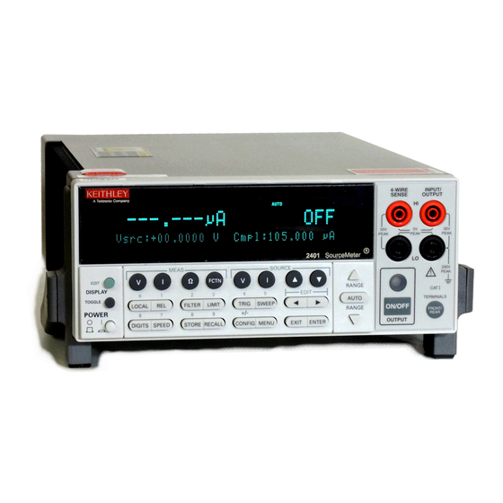
Sourcemeter 2400 series source measure unit
Hide thumbs Also See for SourceMeter 2400:

Advertisement

Series 2400 SourceMeter
Quick Start Guide
2400S-903-01 Rev. E / September 2011
Distribution in the UK & Ireland
Characterisation,
Measurement &
Analysis
Lambda Photometrics Limited
Lambda House Batford Mill
Harpenden Herts AL5 5BZ
United Kingdom
E:
info@lambdaphoto.co.uk
W: www.lambdaphoto.co.uk
T:
+44 (0)1582 764334
F:
+44 (0)1582 712084
A
G
R
E
A
T
E
R
M
E
A
®
S
U
R
E
O
F
C
O
N
F
I
w
w
w
k .
i e
h t
e l
. y
o c
D
E
N
C
E
m

Advertisement

Table of Contents
loading
Need help?

Need help?

Do you have a question about the SourceMeter 2400 and is the answer not in the manual?

Questions and answers

Subscribe to Our Youtube Channel

Summary of Contents for Keithley SourceMeter 2400

  • Page 1 Series 2400 SourceMeter ® Quick Start Guide 2400S-903-01 Rev. E / September 2011 Distribution in the UK & Ireland Lambda Photometrics Limited Lambda House Batford Mill Harpenden Herts AL5 5BZ United Kingdom Characterisation, info@lambdaphoto.co.uk Measurement & W: www.lambdaphoto.co.uk +44 (0)1582 764334 Analysis +44 (0)1582 712084...
  • Page 2 ® Series 2400 SourceMeter Quick Start Guide ©2011, Keithley Instruments, Inc. All rights reserved. Cleveland, Ohio, U.S.A. 2400S-903-01 Rev. E / September 2011 Document Number:...
  • Page 3: Safety Precautions

    Keithley Instruments products are designed for use with electrical signals that are rated Measurement Category I and Measurement Category II, as described in the International Electrotechnical Commission (IEC) Standard IEC 60664. Most measurement, control, and data I/O signals are Measurement Category I and must not be directly connected to mains voltage or to voltage sources with high transient over-voltages.
  • Page 4 To maintain protection from electric shock and fire, replacement components in mains circuits - including the power transformer, test leads, and input jacks - must be purchased from Keithley Instruments. Standard fuses with applicable national safety approvals may be used if the rating and type are the same.
  • Page 5: Table Of Contents

    Table of Contents Section Topic Page Introduction ....................1-2 Source-measure capabilities ..............1-2 Front and rear panels ................. 1-3 Navigating menus and entering numeric data ..........1-4 Menu navigation................... 1-4 Numeric data entry (EDIT keys) ............1-4 Editing source and compliance values ............
  • Page 6: Introduction

    Section 1 Introduction Quick start topics Topic Page Introduction ..................1-1 Source-measure capabilities............1-2 Front and rear panels..............1-3 Navigating menus and entering numeric data........ 1-4 Editing source and compliance values........... 1-4 Basic connections ................1-6 Basic SourceMeter operations ............. 1-10 Settings to optimize performance..........
  • Page 7: Source-Measure Capabilities

    Introduction This guide is designed to familiarize users with fundamental operation (front panel and remote) of the Keithley 2400 Series SourceMeters. For comprehensive information on all aspects of SourceMeter operation, refer to the 2400 Series SourceMeter User’s Manual. Operation information in this guide is divided into four parts; (1) Fundamental source-measure operations, (2) Settings to optimize performance, (3) Features to enhance DUT testing and (4) More testing techniques.
  • Page 8: Front And Rear Panels

    Series 2400 SourceMeter® Quick Start Guide Section 1: Introduction Model 2425: • Source voltage from 5µV to 105V; measure voltage from 1µV to 105.5V. • Source current from 500pA to 3.15A; measure current from 100pA to 3.165A. • Measure resistance from 10µΩ (<10µΩ in manual ohms) to 21.1MΩ. •...
  • Page 9: Navigating Menus And Entering Numeric Data

    Section 1: Introduction Series 2400 SourceMeter® Quick Start Guide Figure 1-2 Rear Panel WARNING: NO INTERNAL OPERATOR SERVICABLE PARTS, SERVICE BY QUALIFIED PERSONNEL ONLY. MADE IN V, Ω, U.S.A. GUARD LISTED SourceMeter 250V 250V LINE FUSE 4ZA4 PEAK PEAK PEAK SLOWBLOW PEAK 2.5A, 250V...
  • Page 10: Editing Procedure

    Series 2400 SourceMeter® Quick Start Guide Section 1: Introduction • DISPLAY EDIT — Selects the source or compliance display field for editing. A blinking cursor will appear in the field to be edited. If no key is pressed within a few seconds, the edit mode will be cancelled automatically.
  • Page 11: Basic Connections

    Section 1: Introduction Series 2400 SourceMeter® Quick Start Guide Basic connections The SourceMeter uses safety jacks for signal connections. To avoid WARNING electric shock: • Do not leave exposed connections. • Properly insulate all external circuits. • The front and rear terminals of the SourceMeters are rated for connection to circuits rated Installation Category I only.
  • Page 12: 4-Wire Connections

    Series 2400 SourceMeter® Quick Start Guide Section 1: Introduction Figure 1-3 2-wire connections 4-WIRE INPUT/ SENSE OUTPUT TERMINALS ON/OFF FRONT/ FRONT/ REAR REAR OUTPUT SourceMeter Front Panel Sense Selection: 2-wire Figure 1-4 4-wire connections 4-WIRE INPUT/ SENSE OUTPUT TERMINALS ON/OFF FRONT/ FRONT/ REAR...
  • Page 13: Cable Guard

    Section 1: Introduction Series 2400 SourceMeter® Quick Start Guide NOTE Specified accuracies for both source and measure are achieved only using 4-wire remote sensing. Cable guard When testing high-impedance DUT (>1GΩ), cable guard is used to drive the shields of cables and test fixtures to minimize leakage currents and input capacitance.
  • Page 14: Ohms Guard

    Series 2400 SourceMeter® Quick Start Guide Section 1: Introduction Figure 1-5 Cable guard connections Guard Shield Test Fixture Connect to earth safety ground using #18 AWG wire or larger. WARNING: NO INTERNAL OPERATOR SERVICAB V, Ω GUARD GUARD SENSE 4-WIRE INPUT/ SENSE OUTPUT...
  • Page 15: Remote Command Programming

    Section 1: Introduction Series 2400 SourceMeter® Quick Start Guide NOTE Guard current (I ) must never exceed 50mA. If it does, guard voltage will become less than the output voltage and corrupt the measurement. Figure 1-6 Guarded ohms measurements V, Ω Guard V, Ω...
  • Page 16: Measure Only (V Or I)

    Series 2400 SourceMeter® Quick Start Guide Section 1: Introduction Table 1-2 Source-measure procedure Procedure Details 1. Select source function. Press SOURCE V or SOURCE I. 2. Set source level. Use DISPLAY EDIT key to place cursor in source arrow keys field (Vsrc or Isrc), use RANGE select range, use edit keys to key in source value, then press ENTER.
  • Page 17: Measure Ohms

    Section 1: Introduction Series 2400 SourceMeter® Quick Start Guide Table 1-3 Measure only (V or I) procedure Procedure Details 1. Select source-measure To measure voltage, press SOURCE I and MEAS V. To functions. measure current, press SOURCE V and MEAS I. 2.
  • Page 18 Series 2400 SourceMeter® Quick Start Guide Section 1: Introduction Use the following menu sequence to select the auto ohms or manual ohms measurement method: Press CONFIG > press MEAS Ω > select SOURCE > select AUTO or MANUAL Ohms source readback With source readback enabled, the SourceMeter measures both V and I and uses these values for the ohms calculation.
  • Page 19: Remote Command Programming

    Section 1: Introduction Series 2400 SourceMeter® Quick Start Guide Offset-compensated ohms Thermal EMFs can corrupt low-resistance measurements. An offset-compensated Ω measurement cancels out unwanted offset by performing the following 2-point measurement process: Offset-Compensated Ω = ΔV / ΔI where:ΔV = V2 - V1 ΔI = I2 - I1 V1 and I1 are V and I measurements with the source set to a specific level.
  • Page 20: Scpi Commands

    Series 2400 SourceMeter® Quick Start Guide Section 1: Introduction NOTE The five element data string is the GPIB default condition. SCPI commands SCPI commands to source-measure and measure only are provided in Table 6, and the commands to measure ohms are provided in Table 7. Table 1-6 SCPI commands;...
  • Page 21 Section 1: Introduction Series 2400 SourceMeter® Quick Start Guide Measure-only example — Table 9 shows a typical command sequence to measure current only. Table 1-8 Command sequence for source-measure example Command* Comments *RST Restore GPIB defaults (one-shot source-measure mode). :SOUR:FUNC VOLT Select voltage source function.
  • Page 22: Settings To Optimize Performance

    Series 2400 SourceMeter® Quick Start Guide Section 1: Introduction Table 1-10 Command sequence for auto ohms example Command* Comments *RST Restore GPIB defaults (one-shot measurement mode). :SENS:FUNC “RES” Select ohms measurement function. :SENS:RES:RANG 200 Select 200Ω range. :SENS:RES:MODE AUTO Select the auto ohms measurement method. :SYST:RSEN ON Select 4-wire sense mode.
  • Page 23: Speed

    Section 1: Introduction Series 2400 SourceMeter® Quick Start Guide Speed Measurement speed is set by setting the integration time of the A/D converter (period of time the input signal is measured). Integration time affects the usable digits, reading noise, and the ultimate reading rate of the instrument.
  • Page 24: Rel (Nulling Offsets)

    Series 2400 SourceMeter® Quick Start Guide Section 1: Introduction Moving filter The first reading conversion is placed in the stack, and is copied to the other stack locations to fill it. Therefore, the first filtered reading is the same as the first reading conversion. The stack type is first-in, first-out.
  • Page 25: Remote Command Programming

    Section 1: Introduction Series 2400 SourceMeter® Quick Start Guide NOTE Rel can also be used to establish a baseline reading. The baseline reading will be subtracted from present and future readings. See “Relative” in Section 8 of the 2400 Series SourceMeter User’s Manual for details.
  • Page 26 Series 2400 SourceMeter® Quick Start Guide Section 1: Introduction Recalling readings To recall readings, press the RECALL key. The buffer location number is the memory location of the recalled reading. Location #0000 indicates that the displayed reading is stored at the first memory location.
  • Page 27: Sweep Operation

    Section 1: Introduction Series 2400 SourceMeter® Quick Start Guide Programming example Table 14 shows a typical command sequence to store and recall readings from the buffer. Table 1-14 Command sequence for data store example Command* Comments *RST Restore GPIB defaults. :SOUR:VOLT 10 Set voltage source to 10V.
  • Page 28 Series 2400 SourceMeter® Quick Start Guide Section 1: Introduction Figure 1-7 Linear staircase sweep Delay Stop Step Delay Step Delay Step Delay Start Bias Measure Measure Measure Measure X = Measurement point Logarithmic staircase sweep This sweep is similar to the linear staircase sweep. The steps, however, are done on a logarithmic scale.
  • Page 29 Section 1: Introduction Series 2400 SourceMeter® Quick Start Guide Figure 1-8 Logarithmic staircase sweep (example) Scale Delay Stop (10) Delay 5.6234 Volts Delay 3.1623 Delay 1.7783 Log Points = 5 Delay Start Bias Measure Measure Measure Measure Measure X = Measurement Point Custom sweep For a custom sweep, the user specifies the number of point in a sweep, and the source level at each point.
  • Page 30 Series 2400 SourceMeter® Quick Start Guide Section 1: Introduction Figure 1-9 Custom pulse sweep (example) Delay Delay Delay Delay Delay Delay Bias 0V Bias Measure Measure Measure Measure Measure Measure Source memory sweep For a source memory sweep, up to 100 setup configurations can be saved in memory. When the sweep is run, the setup at each memory point is recalled.
  • Page 31: Performing Sweeps

    Section 1: Introduction Series 2400 SourceMeter® Quick Start Guide Source ranging There are three options to control source ranging for a sweep; fixed, best fixed, and auto range. With the fixed option selected, the SourceMeter stays on the source range that is selected at the start of the sweep.
  • Page 32 Series 2400 SourceMeter® Quick Start Guide Section 1: Introduction The readings will be stored in the buffer if a finite count sweep was run. Performing a log staircase sweep Perform the following steps to run a log staircase sweep: Configure the source and measure functions. The source level you set becomes the bias level for the sweep.
  • Page 33 Section 1: Introduction Series 2400 SourceMeter® Quick Start Guide NOTE Table 15 does not provide a complete listing of sweep commands. Documentation for all sweep commands can be found in Section 10 of the 2400 Series Source-Meter User’s Manual Table 1-15 SCPI commands;...
  • Page 34 Series 2400 SourceMeter® Quick Start Guide Section 1: Introduction Programming examples Programming examples for a linear, logarithmic, custom, and source memory sweep are provided in Table 16. Table 1-16 Command sequences for sweep examples Command* Comments Linear staircase sweep: See Figure 6 *RST Restore GPIB defaults (source V, measure I).
  • Page 35: Limit Testing

    Section 1: Introduction Series 2400 SourceMeter® Quick Start Guide Table 1-16 (cont.) Command sequences for sweep examples Command* Comments Source memory sweep: Three point sweep; source V, calculate power, source I. ‘Memory location 001 setup: *RST Restore GPIB defaults :SOUR:VOLT:LEV 15 Set voltage source to 15V.
  • Page 36 Series 2400 SourceMeter® Quick Start Guide Section 1: Introduction NOTE Limit testing using a component handler to perform binning operations is summarized in the “More testing techniques” section of this guide. For complete details on all aspects of limit testing, see the 2400 Series SourceMeter User’s Manual, Section 12.
  • Page 37 Section 1: Introduction Series 2400 SourceMeter® Quick Start Guide Remote command programming SCPI commands SCPI commands for basic non-binning limit testing are listed in Table 17. NOTE Table 17 does not provide a complete listing of limit commands. See Sections 12 and 18 of the 2400 Series SourceMeter User’s Manual for complete documentation.
  • Page 38: Math Functions

    Series 2400 SourceMeter® Quick Start Guide Section 1: Introduction Table 1-18 Command sequence for Limit 2 test example Command* Comments *RST Restore GPIB defaults. :SENS:FUNC “RES” Select ohms meaurement function. :CALC2:LIM2:STAT ON Enable Limit 2 test. :CALC2:FEED RES Use ohms for limits comparison. :CALC2:LIM2:LOW 950 Set lower limit to 950Ω.
  • Page 39 Section 1: Introduction Series 2400 SourceMeter® Quick Start Guide Ω NOTE Offset-compensated is also available from the CONFIG OHMS Ω menu. Using Offset-compensated from this menu automatically selects zero as one of the source values. For details, see “Measure ohms” in the “Basic SourceMeter operations” section of this guide. Voltage coefficient High value resistors exhibit a change in resistance with a change in applied voltage.
  • Page 40 Series 2400 SourceMeter® Quick Start Guide Section 1: Introduction Percent deviation This calculation provides the percent deviation between the normal display reading and the user specified reference value: – ------------------ - × % Deviation = where:X is the normal display measurement reading. Y is the reference value.
  • Page 41: Pulse Mode (Model 2430 Only)

    Section 1: Introduction Series 2400 SourceMeter® Quick Start Guide Table 1-20 Command sequence for power measurement example Command* Comments *RST Restore GPIB defaults (source 0V, measure I). :SOUR:VOLT:RANG 0.2 Select the 200mV source range. :SENS:FUNC “VOLT”, “CURR” Select V and I meaurement functions. :SENS:CURR:PROT 100e-3 Set current compliance to 100mA.
  • Page 42 Series 2400 SourceMeter® Quick Start Guide Section 1: Introduction Figure 1-10 Pulse-measure timing Meas Delay 80μsec Pulse Width Output Off-Time (Output On-Time) 0V or 0A Meas 2.9ms Ref & Delay = Pulse width delay Zero 80μsec = Minimum pulse width overhead Meas Sig = Signal measurement 2.9ms = Minimum output off-time overhead Meas Ref &...
  • Page 43 Section 1: Introduction Series 2400 SourceMeter® Quick Start Guide 10A range limitations Pulse width The maximum pulse width for the 10A range (source or measure) is 2.5msec. If the setting is >2.5msec, the SourceMeter will limit the pulse width to 2.5msec. Charge energy consumption Energy for pulses are provided by an internal bank of capacitors.
  • Page 44 Series 2400 SourceMeter® Quick Start Guide Section 1: Introduction INFINITE - Use to set arm count to infinity. Trigger count - Use the following menu sequence to set the trigger count: Press CONFIG > press TRIG > select TRIG LAYER > select COUNT > set TRIG COUNT Enable/disable auto zero Use the following menu sequence to enable or disable auto zero: Press MENU >...
  • Page 45 Section 1: Introduction Series 2400 SourceMeter® Quick Start Guide Auto range — Auto range is invalid while in the Pulse Mode. Source delay — In the DC Mode, source delay is the delay between the source and measure actions. When the Pulse Mode is selected, source delay is replaced by pulse delay. Pulse delay is the user set delay that occurs during the off-time portion of the pulse period.
  • Page 46 Distribution in the UK & Ireland Lambda Photometrics Limited Keithley Instruments, Inc. Lambda House Batford Mill Corporate Headquarters • 28775 Aurora Road • Cleveland, Ohio 44139 • 440-248-0400 • Fax: 440-248-6168 • 1-888-KEIT LEY • www.keithley.com Harpenden Herts AL5 5BZ United Kingdom Characterisation, info@lambdaphoto.co.uk...

Table of Contents

Save PDF