
Related Manuals for Keithley SourceMeter 2400 Series


Summary of Contents for Keithley SourceMeter 2400 Series
- Page 1 Model 2400 Series ® SourceMeter Quick Results Guide A G R E A T E R M E A S U R E O F C O N F I D E N C E...
- Page 2 WARRANTY Keithley Instruments, Inc. warrants this product to be free from defects in material and workmanship for a period of 1 year from date of shipment. Keithley Instruments, Inc. warrants the following items for 90 days from the date of shipment: probes, cables, rechargeable batteries, diskettes, and documentation.
- Page 3 ® 2400 Series SourceMeter Quick Results Guide ©2000, Keithley Instruments, Inc. All rights reserved. Cleveland, Ohio, U.S.A. Third Printing, May 2002 Document Number: 2400S-903-01 Rev. C...
- Page 4 Revision B (Document Number 2400S-903-01) .............. April 2001 Revision C (Document Number 2400S-903-01) ............... May 2002 All Keithley product names are trademarks or registered trademarks of Keithley Instruments, Inc. Other brand names are trademarks or registered trademarks of their respective holders.
- Page 5 Keithley products are designed for use with electrical signals that are rated Installation Category I and Installation Category II, as described in the International Electrotechnical Commission (IEC) Standard IEC 60664. Most measurement, control, and data I/O signals are Installation Category I and must not be directly connected to mains voltage or to voltage sources with high tran- sient over-voltages.
- Page 6 To maintain protection from electric shock and fire, replacement components in mains circuits, including the power transformer, test leads, and input jacks, must be purchased from Keithley Instruments. Standard fuses, with applicable national safety ap- provals, may be used if the rating and type are the same. Other components that are not safety related may be purchased from other suppliers as long as they are equivalent to the original component.
-
Page 7: Table Of Contents
Table of Contents Introduction ................... Source-measure capabilities ............Front and rear panels ..............Navigating menus and entering numeric data ....... Menu navigation ..............Numeric data entry (EDIT keys) ..........Editing source and compliance values .......... Editing keys ................Editing procedure ..............Toggling the source and measure display fields ..... - Page 8 List of Illustrations Figure 1 Front panel ................Figure 2 Rear panel .................. Figure 3 2-wire connections ..............Figure 4 4-wire connections ..............Figure 5 Cable guard connections ............Figure 6 Guarded ohms measurements ........... Figure 7 Linear staircase sweep ............. Figure 8 Logarithmic staircase sweep (example) ........
-
Page 9: Introduction
Introduction This guide is designed to familiarize users with fundamental operation (front panel and remote) of the Keithley 2400 Series SourceMeters. For comprehensive information on all aspects of SourceMeter operation, refer to the 2400 Series SourceMeter User’s Manual. Operation information in this guide is divided into four parts; (1) Fundamental source- measure operations, (2) Settings to optimize performance, (3) Features to enhance DUT testing and (4) More testing techniques. - Page 10 Quick Results Guide Model 2410: • Source voltage from 5µV to 1100V; measure voltage from 1µV to 1100V. • Source current from 50pA to 1.05A; measure current from 10pA to 1.055A. • Measure resistance from 100µΩ (<100µΩ in manual ohms) to 211MΩ. •...
-
Page 11: Front And Rear Panels
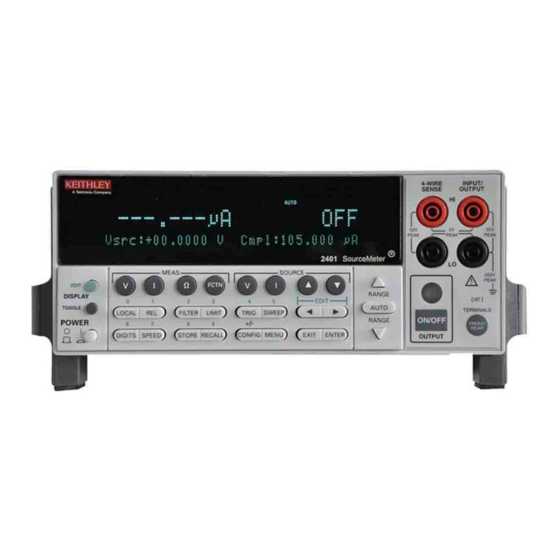
Quick Results Guide Front and rear panels The front and rear panels of the Model 2400 SourceMeter are shown in Figures 1 and 2. The front and rear panels of the other SourceMeter models are similar. The use of the various instru- ment controls and connectors will be explained throughout this guide. -
Page 12: Navigating Menus And Entering Numeric Data
Quick Results Guide Navigating menus and entering numeric data Menu navigation Many operating modes for the SourceMeter are configured using front panel menus. Throughout this guide, menu navigation will be presented as a sequence of key presses and menu item selections. For example, the following sequence selects the auto ohms source mode: Press CONFIG >... -
Page 13: Editing Procedure
Quick Results Guide Editing procedure Press the DISPLAY EDIT key to place the blinking cursor in either the source or com- pliance display field to be edited. If desired, use the RANGE keys to select the desired source or compliance range. -
Page 14: Front/Rear Terminals Selection
Quick Results Guide Front/rear terminals selection The input/output and sense terminals are accessible from both the front and rear panels, while the guard terminals and chassis ground are only accessible from the rear panel. On the front panel, press the FRONT/REAR key to toggle between front and rear. The REAR annunci- ator indicates that the rear terminals are selected. -
Page 15: 4-Wire Connections
Quick Results Guide 4-wire connections Connections for 4-wire local sensing are shown in Figure 4. Use 4-wire remote sensing for the following source-measure conditions: • Test circuit impedance is <1kΩ. • Optimum ohms, V-source, and/or V-measure accuracy is required. With 4-wire sensing selected, the 4W annunciator is on. The following menu sequence selects 4-wire remote sensing: Press CONFIG >... -
Page 16: Cable Guard
Quick Results Guide Cable guard When testing high-impedance DUT (>1GΩ), cable guard is used to drive the shields of cables and test fixtures to minimize leakage currents and input capacitance. A typical connec- tion scheme using cable guard is shown in Figure 5. The following menu sequence selects cable guard: Press CONFIG >... -
Page 17: Figure 6 Guarded Ohms Measurements
Quick Results Guide NOTE Ohms guard cannot be used for high current (>100mA) ranges. Ohms guard cannot be selected if already on a high current range. Conversely, if ohms guard is already selected, a high current range cannot be selected. The following menu sequence selects ohms guard: Press CONFIG >... -
Page 18: Remote Command Programming
Quick Results Guide Remote command programming Table 1 lists the SCPI commands to select terminals, sense, and cable guard. Table 1 SCPI commands; terminals, sense, and cable guard Command Description :ROUTe:TERMinals <name> Selects terminals; <name> = FRONt or REAR. :SYSTem:RSENse <b> Selects sense mode;... -
Page 19: Table 2 Source-Measure Procedure
Quick Results Guide Table 2 Source-measure procedure Procedure Details 1. Select source function. Press SOURCE V or SOURCE I. 2. Set source level. Use DISPLAY EDIT key to place cursor in source field (Vsrc or Isrc), use RANGE keys to select range, use edit keys to key in source value, then press ENTER. -
Page 20: Measure Only (V Or I)
Quick Results Guide Measure only (V or I) The SourceMeter can be used to measure voltage only (voltmeter) or current only (amme- ter). The procedure to measure only is provided in Table 3. Table 3 Measure only (V or I) procedure Procedure Details 1. -
Page 21: Measure Ohms
Quick Results Guide Measure ohms Measurement methods There are two methods to measure resistance; auto ohms and manual ohms. In auto ohms, the SourceMeter operates as a conventional constant-current source ohmmeter. You simply select an ohms measurement range (or auto range) and take the reading from the display. In manual ohms, the SourceMeter uses the V/I measurement method. -
Page 22: Table 5 Manual Ohms Measurement Procedure
Quick Results Guide Table 5 Manual ohms measurement procedure Procedure Details Press MEAS Ω. 1. Select ohms measurement function. Press CONFIG > press MEAS Ω > select SOURCE 2. Select manual ohms measurement method. > select MANUAL. 3. Select source, set source level, and See steps 1, 2, and 3 of Table 2. -
Page 23: Remote Command Programming
Quick Results Guide NOTE Manual offset-compensated ohms is also available as a math function (FCTN). This math function allows you to specify both source levels (see “Math functions” in “Features to enhance DUT testing.” In-circuit ohms measurements Ohms guard allows you make accurate in-circuit ohms measurements on resistor networks. These measurements are covered in Advanced operation. -
Page 24: Table 6 Scpi Commands; Source-Measure And Measure Only
Quick Results Guide SCPI commands SCPI commands to source-measure and measure only are provided in Table 6, and the com- mands to measure ohms are provided in Table 7. Table 6 SCPI commands; source-measure and measure only Command Description :SOURce:FUNCtion <name> Select source function;... -
Page 25: Table 8 Command Sequence For Source-Measure Example
Quick Results Guide Programming examples Source-measure example — Table 8 shows a typical command sequence to source 10V and measure current on the 10mA range. Measure-only example — Table 9 shows a typical command sequence to measure current only. Table 8 Command sequence for source-measure example Command* Comments... -
Page 26: Table 10 Command Sequence For Auto Ohms Example
Quick Results Guide Auto ohms example — Table 10 shows a typical command sequence to use auto ohms to measure resistance. Note that 4-wire sensing is used for this example. See Basic connections for details on sensing. Manual ohms example — Table 11 shows a typical command sequence to use manual ohms to measure resistance. -
Page 27: Settings To Optimize Performance
Quick Results Guide Settings to optimize performance Range To achieve best accuracy, the SourceMeter should be on the lowest possible measurement range. In most situations, auto range can be used to automatically select the best range. Auto range is controlled (enabled/disabled) by the AUTO range key (AUTO annunciator indicates auto range is enabled). -
Page 28: Digits
Quick Results Guide Digits The SourceMeter can display readings at 3 -digit, 4 -digit, 5 -digit or 6 -digit resolu- tion. In situations where the last digits of the reading are noisy, you can turn those digits off by decreasing display resolution. To set display resolution, press the DIGITS key until the desired number of digits are dis- played. -
Page 29: Rel (Nulling Offsets)
Quick Results Guide Response time Filter type and count have the following effects on the time needed to display, store, or out- put a filtered reading: • Filter type: The moving filter type yields faster filtered readings since it doesn’t have to re-fill the entire stack (as is the case for the repeating filter). -
Page 30: Remote Command Programming
Quick Results Guide Remote command programming The SCPI commands for speed, digits, filter, and rel are listed in Table 12. The commands for ranging are listed in Tables 6 and 7. Table 12 SCPI commands; speed, digits, filter, and rel Command Description Speed commands... -
Page 31: Features To Enhance Dut Testing
Quick Results Guide Features to enhance DUT testing Data store The data store (buffer) can store from 1 to 2500 readings, and provides statistical data on the stored readings. Storing readings To store readings, press STORE, key in the number of readings to store, and press ENTER. The star (*) annunciator indicates that the buffer is enabled. -
Page 32: Table 13 Scpi Commands; Data Store
Quick Results Guide Remote command programming SCPI commands SCPI commands to configure and control the buffer are listed in Table 13. NOTE Table 13 does not provide a complete listing of buffer commands. Documentation for all buffer commands (including the ones for buffer statistics) can be found in Section 9 of the 2400 Series SourceMeter User’s Manual. -
Page 33: Sweep Operation
Quick Results Guide Sweep operation Sweep types The four available sweep types are linear staircase, logarithmic staircase, custom, and source memory. Linear staircase sweep When the sweep shown in Figure 7 is triggered to start, the output will go from the bias level to the source level. -
Page 34: Figure 8 Logarithmic Staircase Sweep (Example)
Quick Results Guide Logarithmic staircase sweep This sweep is similar to the linear staircase sweep. The steps, however, are done on a loga- rithmic scale. The symmetrical log points for the steps are determined by the specified number of sweep points. Figure 8 shows a 5-point log sweep from 1 to 10V. With the desired source (V or I) selected, use the following menu sequence to set the start and stop levels, and the number of sweep points (2 to 2500): Press CONFIG >... -
Page 35: Figure 9 Custom Pulse Sweep (Example)
Quick Results Guide Custom sweep For a custom sweep, the user specifies the number of point in a sweep, and the source level at each point. Figure 9 shows a 6-point, 50% duty cycle pulse sweep. The specified voltage level at points P0, P2 and P4 is 1V, while the voltage level at P1, P3 and P5 is 0V. With the desired source (V or I) selected, use the following menu sequence to specify the number of sweep points and the source level at each point: Press CONFIG >... - Page 36 Quick Results Guide Source memory sweep For a source memory sweep, up to 100 setup configurations can be saved in memory. When the sweep is run, the setup at each memory point is recalled. This allows multiple functions and math expressions to be used in a sweep. A SourceMeter setup configuration is saved in memory by performing the following menu sequence: Press MENU >...
-
Page 37: Performing Sweeps
Quick Results Guide Source ranging There are three options to control source ranging for a sweep; fixed, best fixed, and auto range. With the fixed option selected, the SourceMeter stays on the source range that is selected at the start of the sweep. With best fixed selected, the largest source value in the sweep determines the range. - Page 38 Quick Results Guide Performing a log staircase sweep Perform the following steps to run a log staircase sweep: Configure the source and measure functions. The source level you set becomes the bias level for the sweep. Configure the log staircase sweep, including start and stop values and number of points, as previously explained.
-
Page 39: Table 15 Scpi Commands; Sweeping
Quick Results Guide Remote command programming SCPI commands SCPI commands for linear, logarithmic and custom sweeps are listed in Table 15. NOTE Table 15 does not provide a complete listing of sweep commands. Documentation for all sweep commands can be found in Section 10 of the 2400 Series Source-Meter User’s Manual. -
Page 40: Figure 7 Linear Staircase Sweep
Quick Results Guide Programming examples Programming examples for a linear, logarithmic, custom, and source memory sweep are provided in Table 16. Table 16 Command sequences for sweep examples Command* Comments Linear staircase sweep: See Figure 6 *RST Restore GPIB defaults (source V, measure I). :SOUR:VOLT 0 Set bias level to 0V. - Page 41 Quick Results Guide Table 16 (cont.) Command sequences for sweep examples Command* Comments Source memory sweep: Three point sweep; source V, calculate power, source I. ‘Memory location 001 setup: *RST Restore GPIB defaults :SOUR:VOLT:LEV 15 Set voltage source to 15V. :SOUR:MEM:SAVE 1 Save setup in memory location 001.
-
Page 42: Limit Testing
Quick Results Guide Limit testing There is one hardware test (Limit 1; compliance) and 10 software tests (Limits 2, 3, 5-12; high/low limits) available for limit testing. (Limit 4 is reserved for the contact check option.) For basic, pass/fail, non-binning limit testing, you should use only one software test at a time. NOTE Limit testing using a component handler to perform binning operations is summa- rized in the “More testing techniques”... -
Page 43: Table 17 Scpi Commands; Basic Non-Binning Limit Testing
Quick Results Guide HILIM - Use to enter the high limit value. You will then be prompted to enter the bit pattern for binning operations. Since binning operations are being done at this time, simply press ENTER or EXIT. Limit testing operation Connect the DUT to the SourceMeter. -
Page 44: Math Functions
Quick Results Guide Programming example The programming example in Table 18 tests 1kΩ resistors. If the tested resistor is within 5% of it’s nominal value, it will pass the test. Otherwise the test will fail. Table 18 Command sequence for Limit 2 test example Command* Comments *RST... - Page 45 Quick Results Guide Offset-compensated Ω Thermal EMFs can corrupt low-resistance measurements. An offset-compensated Ω measurement cancels out unwanted offset by performing the following 2-point measurement process: Offset-Compensated Ω = ∆V / ∆I where: ∆V = V2 - V1 ∆I = I2 - I1 V1 and I1 are V and I measurements with the source set to a specific level.
- Page 46 Quick Results Guide Varistor alpha Determines ALPHA (α), which is the logarithmic ratio of two voltage measurement points on a non-linear V-I curve. ⁄ log I2 I1 α ------------------------------ - ⁄ log V2 V1 where: V1 is the voltage measurement at the first I-Source point (I1). V2 is the voltage measurement at the second I-Source point (I2).
-
Page 47: Table 19 Scpi Commands; Built-In Math Functions
Quick Results Guide Remote command programming SCPI commands SCPI commands for the built-in math functions are listed in Table 19. NOTE The percent deviation math function is not provided as a built-in math function for remote operation. However, it can be configured as a user-defined expression (see CALCulate[1] commands in Section 18 of the 2400 Series SourceMeter User’s Manual). -
Page 48: Pulse Mode (Model 2430 Only)
Quick Results Guide Pulse mode (Model 2430 only) While in the Pulse Mode, the Model 2430 can output one or more pulses. It can output cur- rent pulses up to 10.5A at 105V, or voltage pulses up to 105V at 10.5A. For details on Pulse Mode operation, see the 2400 Series SourceMeter User’s Manual, Section 5. - Page 49 Quick Results Guide Output off-time — As shown in Figure 10, the output off-time consists of a minimum over- head (2.9msec), the time it takes to measure the reference and zero, and the user-set pulse delay (PD). For example, if the measure speed is set to 0.1 PLC, it will take 3.334msec to measure the reference and zero (2 x 1.667msec).
- Page 50 Quick Results Guide If a consistent pulse period is not required for your test, you can use the 10A range to output fast, high energy (>8% duty cycle) pulses. With pulse delay set to 0sec, each subsequent pulse will output as soon as the capacitors become sufficiently charged. Pulse Mode configuration Select Pulse Mode, set pulse width and pulse delay Use the following menu sequence to select the Pulse Mode:...
- Page 51 Quick Results Guide Pulse Mode operation WARNING Hazardous voltage (≥30V rms) can appear on input/output LO when per- forming fast pulse operations. To eliminate this shock hazard connect the LO terminal to chassis ground or to a known safety earth ground. If using the front panel terminals, ground front panel LO.
-
Page 52: Table 21
Quick Results Guide Source delay — In the DC Mode, source delay is the delay between the source and measure actions. When the Pulse Mode is selected, source delay is replaced by pulse delay. Pulse delay is the user set delay that occurs during the off-time portion of the pulse period. Trigger delay —... - Page 53 Specifications are subject to change without notice. All Keithley trademarks and trade names are the property of Keithley Instruments, Inc. All other trademarks and trade names are the property of their respective companies. Keithley Instruments, Inc. 28775 Aurora Road • Cleveland, Ohio 44139 • 440-248-0400 • Fax: 440-248-6168 1-888-KEITHLEY (534-8453) •...
Need help?
Do you have a question about the SourceMeter 2400 Series and is the answer not in the manual?
Questions and answers