Keithley Interactive SourceMeter 2450 User Manual
Instrument
Hide thumbs
Also See for Interactive SourceMeter 2450:
- Reference manual (878 pages) ,
- Application note (6 pages) ,
- Declassification and security instructions (7 pages)

Subscribe to Our Youtube Channel
Related Manuals for Keithley Interactive SourceMeter 2450


Summary of Contents for Keithley Interactive SourceMeter 2450
- Page 1 Model 2450 Interactive SourceMeter Instrument User’s Manual 2450-900-01 Rev. C / December 2013 *P245090001C* 2450-900-01C A Great er Me a s ure of C o nf i d en c e...
- Page 2 © 2013, Keithley Instruments, Inc. Cleveland, Ohio, U.S.A. All rights reserved. Any unauthorized reproduction, photocopy, or use of the information herein, in whole or in part, without the prior written approval of Keithley Instruments, Inc. is strictly prohibited. ® ® ®...
- Page 3 Keithley Instruments products are designed for use with electrical signals that are measurement, control, and data I/O connections, with low transient overvoltages, and must not be directly connected to mains voltage or to voltage sources with high transient overvoltages.
- Page 4 (note that selected parts should be purchased only through Keithley Instruments to maintain accuracy and functionality of the product). If you are unsure about the applicability of a replacement component, call a Keithley Instruments office for information.
-
Page 5: Table Of Contents
Table of Contents Introduction ......................... 1-1 Welcome ..........................1-1 Introduction to this manual ....................1-1 Extended warranty ....................... 1-1 Contact information ......................1-2 CD-ROM contents ........................ 1-2 Organization of manual sections ..................1-3 Applications .......................... 1-3 Using the front-panel interface .................. 2-1 Front panel overview ...................... - Page 6 Table of Contents Model 2450 Interactive SourceMeter® Instrument User's Manual Making basic front-panel measurements ..............4-1 Introduction .......................... 4-1 Equipment required for this application ................4-2 Device connections ......................4-2 Making front-panel measurements ..................4-2 How to make front-panel measurements .................. 4-3 Measuring low-resistance devices ................
- Page 7 Model 2450 Interactive SourceMeter® Instrument User's Manual Table of Contents Remote control of FET testing using SCPI commands ............7-5 Set up the application using SCPI commands with the trigger model ........7-6 Set up the application using SCPI commands in a linear sweep ..........7-8 Remote control of FET testing using TSP commands ............
-
Page 8: Introduction
Welcome ® Thank you for choosing a Keithley Instruments product. The Model 2450 Interactive SourceMeter instrument is a precise, low-noise instrument that combines a stable DC power supply, true current source, electronic load, and a high-impedance multimeter. The design of this instrument features intuitive setup and control, enhanced signal quality and range, and better resistivity and resistance capabilities than similar products on the market. -
Page 9: Contact Information
If you have any questions after you review the information in this documentation, please contact your local Keithley Instruments office, sales partner, or distributor, or call Keithley Instruments corporate headquarters (toll-free inside the U.S. and Canada only) at 1-888-KEITHLEY (1-888-534-8453), or from outside the U.S. -
Page 10: Organization Of Manual Sections
Applications In addition to using the Keithley Instruments Model 2450 as a stand-alone instrument, you can control the Model 2450 from a remote interface. This manual provides application examples that show you how to perform tests from the front panel and using a remote interface. These applications are presented after the summary information about the Model 2450. -
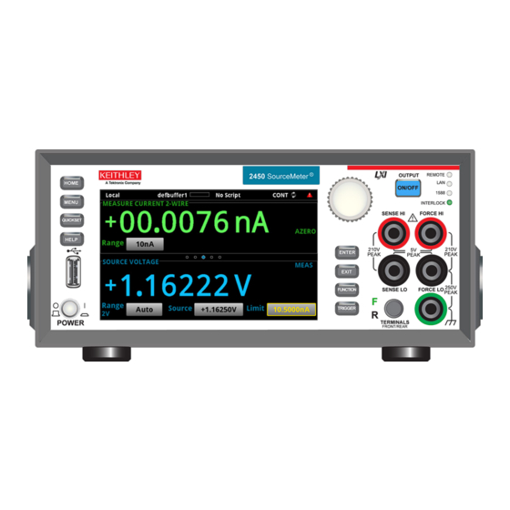
Page 11: Using The Front-Panel Interface
Section 2 Using the front-panel interface In this section: Front panel overview ..............2-1 Power the instrument on or off ..........2-3 Turning the Model 2450 output on or off ........2-4 Using the touchscreen interface ..........2-5 Store measurements on a USB flash drive ......2-7 Saving screen captures to USB flash drive ...... - Page 12 Note that 1588 functionality is not supported at this time. This functionality will be made available with a firmware update. See the Model 2450 Release Notes or Keithley Instruments website (http://www.keithley.com) for details. Illuminates when the interlock is enabled. INTERLOCK LED...
-
Page 13: Power The Instrument On Or Off
Model 2450 Interactive SourceMeter® Instrument User's Manual Section 2: Using the front-panel interface Chassis connection Banana jack connector that provides a chassis connection. Power the instrument on or off Follow the steps below to connect the Model 2450 to line power and turn on the instrument. The Model 2450 operates from a line voltage of 100 V to 240 V at a frequency of 50 Hz or 60 Hz. -
Page 14: Turning The Model 2450 Output On Or Off
Section 2: Using the front-panel interface Model 2450 Interactive SourceMeter® Instrument User's Manual To turn a Model 2450 on or off: 1. Before turning the instrument on, disconnect any devices under test (DUTs) from the Model 2450. 2. To turn your instrument on, press the front-panel POWER switch to place it in the on (|) position. The instrument displays a status bar as it powers on. -
Page 15: Using The Touchscreen Interface
Model 2450 Interactive SourceMeter® Instrument User's Manual Section 2: Using the front-panel interface Using the touchscreen interface The touchscreen display gives you quick front-panel access to source and measure settings, system configuration, instrument and test status, reading buffer information, and other instrument functionality. - Page 16 Section 2: Using the front-panel interface Model 2450 Interactive SourceMeter® Instrument User's Manual STATISTICS swipe screen The STATISTICS swipe screen contains information about the state of the active buffer and the readings in it. You can use the Clear Stats button on this screen to clear the data that is used in the statistics calculations.
-
Page 17: Menu Overview
Model 2450 Interactive SourceMeter® Instrument User's Manual Section 2: Using the front-panel interface Menu overview To access the main menu, press the MENU key on the Model 2450 front panel. The figure below shows the organization of the main menu. Figure 7: Model 2450 main menu The main menu includes six submenus. -
Page 18: Saving Screen Captures To Usb Flash Drive
Section 2: Using the front-panel interface Model 2450 Interactive SourceMeter® Instrument User's Manual Saving screen captures to USB flash drive You can save the content of the front-panel display to graphic file. The instrument saves these graphic files, also known as screen captures, in sequentially-numbered files to the USB flash drive. To save the screen capture: 1. -
Page 19: Using A Remote Interface
Section 3 Using a remote interface In this section: Remote communication interfaces ........... 3-1 Supported remote interfaces ............ 3-1 GPIB communications .............. 3-1 LAN communications ............... 3-4 USB communications ............... 3-6 Using the web interface ............3-12 Determining the command set you will use ......3-15 Remote communication interfaces You can choose from one of several communication interfaces to send commands to and receive responses from the Model 2450. -
Page 20: Install The Gpib Driver Software
Install the GPIB driver software Check the documentation for your GPIB controller for information about where to acquire drivers. Keithley Instruments also recommends that you check the website of the GPIB controller for the latest version of drivers or software. -
Page 21: Set The Gpib Address
Model 2450 Interactive SourceMeter® Instrument User's Manual Section 3: Using a remote interface Figure 9: IEEE-488 connection example Set the GPIB address The factory sets the GPIB address value to 18. You can set the address to any address from 0 to 30 if it is unique in the system. -
Page 22: Lan Communications
Section 3: Using a remote interface Model 2450 Interactive SourceMeter® Instrument User's Manual LAN communications You can communicate with the instrument using a local area network (LAN). When you connect using a LAN, you can use a web browser to access the internal web page of the instrument and change some of the instrument settings. -
Page 23: Set Up Lan Communications On The Computer
Model 2450 Interactive SourceMeter® Instrument User's Manual Section 3: Using a remote interface To set up automatic IP address selection using the front panel: 1. From the Home screen, press MENU. 2. Under System, select Communication. 3. Select the LAN tab. 4. -
Page 24: Usb Communications
USB communications To use the rear-panel USB port, you must have the Virtual Instrument Software Architecture (VISA) layer on the host computer. See "How to install the Keithley I/O Layer" in the Model 2450 Reference Manual for more information. VISA contains a USB class driver for the USB Test and Measurement Class (USBTMC) protocol that, ®... -
Page 25: Connecting A Computer To The Model 2450 Using Usb
INSTR: Use the USBTMC protocol To determine these parameters, you can run the Keithley Configuration Panel, which automatically detects all instruments connected to the computer. If you installed the Keithley I/O Layer, you can access the Keithley Configuration Panel through the ® ®... - Page 26 Model 2450 Interactive SourceMeter® Instrument User's Manual To use the Keithley Configuration Panel to determine the VISA resource string: 1. Click Start > All Programs > Keithley Instruments > Keithley Configuration Panel. The Select Operation dialog box is displayed. Figure 10: Select Operation dialog box 2.
- Page 27 Model 2450 Interactive SourceMeter® Instrument User's Manual Section 3: Using a remote interface 3. Click Next. The Select Communication Bus dialog box is displayed. Figure 11: Select Communication Bus dialog box 4. Select USB. 5. Click Next. The Select Instrument Driver dialog box is displayed. 2450-900-01 Rev.
- Page 28 Section 3: Using a remote interface Model 2450 Interactive SourceMeter® Instrument User's Manual Figure 12: Select Instrument Driver dialog box 6. Select Auto-detect Instrument Driver - Model. 7. Click Next. The Configure USB Instrument dialog box is displayed with the detected instrument VISA resource string visible.
- Page 29 9. In the Virtual Instrument Name box, enter a name that you want to use to refer to the instrument. 10. Click Finish. 11. Click Cancel to close the Wizard. 12. Save the configuration. From the Keithley Configuration Panel, select File > Save. 2450-900-01 Rev. C / December 2013 3-11...
-
Page 30: Using The Web Interface
Model 2450 Interactive SourceMeter® Instrument User's Manual Verify the instrument through the Keithley Communicator: 1. Click Start > All Programs > Keithley Instruments > Keithley Communicator. 2. Select File > Open Instrument to open the instrument you just named. Figure 14: Keithley Communicator Open Instrument 3. -
Page 31: Lan Troubleshooting Suggestions
Model 2450 Interactive SourceMeter® Instrument User's Manual Section 3: Using a remote interface LAN troubleshooting suggestions If you are unable to connect to the web interface of the instrument, check the following items: • Verify that the network cable is in the LAN port on the rear panel of the instrument, not one of the ®... -
Page 32: Web Interface Home Page
Section 3: Using a remote interface Model 2450 Interactive SourceMeter® Instrument User's Manual Web interface Home page Figure 15: Model 2450 web interface Home page The Home page of the web interface gives you basic information about the instrument, including: •... -
Page 33: Reviewing Lan Trigger Events In The Event Log
Series 2400 instruments. You cannot combine the command sets. As delivered from Keithley Instruments, the Model 2450 is set to work with the Model 2450 SCPI command set. If you choose the SCPI 2400 command set, you will not have access to some of the extended ranges and other features that are now available using the SCPI command set. - Page 34 Section 3: Using a remote interface Model 2450 Interactive SourceMeter® Instrument User's Manual To change to the SCPI command set from a remote interface: Send the command: *LANG SCPI Reboot the instrument. To change to the TSP command set from a remote interface: Send the command: *LANG TSP Reboot the instrument.
-
Page 35: Making Basic Front-Panel Measurements
Section 4 Making basic front-panel measurements In this section: Introduction ................4-1 Equipment required for this application ........4-2 Device connections ..............4-2 Making front-panel measurements ........... 4-2 Introduction You can use the Model 2450 to source and make measurements from the front panel. Make sure you select the source and measure functions before you make changes to other instrument settings. -
Page 36: Equipment Required For This Application
Model 2450 Interactive SourceMeter instrument • Two insulated banana cables; you can use the set that is provided with the Model 2450, the Keithley Instruments Model 8608 Model 8608 High-Performance Clip Lead Set • One 10 kΩ resistor to test Device connections Connect the Model 2450 to the resistor in a 2-wire (local sense) configuration. -
Page 37: How To Make Front-Panel Measurements
Model 2450 Interactive SourceMeter® Instrument User's Manual Section 4: Making basic front-panel measurements How to make front-panel measurements To make a measurement from the front panel: 1. Press the POWER switch on the front panel to turn on the instrument or cycle power if the instrument is already on. -
Page 38: Measuring Low-Resistance Devices
One Model 2450 Interactive SourceMeter instrument • For front-panel connections, use four insulated banana cables, such as the Keithley Instruments Model 8608 Model 8608 High-Performance Clip Lead Set (one set included with the Model 2450; you will need another set) •... - Page 39 Section 5: Measuring low-resistance devices Model 2450 Interactive SourceMeter® Instrument User's Manual To use the 4-wire connection method: • Connect one set of test leads to the FORCE LO and FORCE HI terminals; this setup forces a current through the device under test. •...
- Page 40 This 4-wire measurement eliminates the resistance of the test leads in the measurement. The figure below shows the front-panel connections. You can make these connections with four insulated banana cables, such as two sets of the Keithley Instruments Model 8608 High-Performance Clip Lead Set.
-
Page 41: Low-Resistance Measurements
Section 5: Measuring low-resistance devices Model 2450 Interactive SourceMeter® Instrument User's Manual Low-resistance measurements This application demonstrates how to use the Model 2450 to measure a low-resistance device. You can measure from the front panel or over the remote interface using SCPI code or TSP code. For this application, you will: •... -
Page 42: View The Measurements On The Front-Panel Trend Swipe Screen
Model 2450 Interactive SourceMeter® Instrument User's Manual Section 5: Measuring low-resistance devices View the measurements on the front-panel TREND swipe screen You can view the resistance measurements as a function of time on the front-panel TREND swipe screen. To access the TREND swipe screen, swipe the bottom part of the Home screen to the right. The graph in the figure below is displayed. -
Page 43: Set Up The Low-Resistance Application Using Scpi Commands
Section 5: Measuring low-resistance devices Model 2450 Interactive SourceMeter® Instrument User's Manual Figure 22: Model 2450 remote interface connections Set up the low-resistance application using SCPI commands This sequence of SCPI commands makes 100 low-resistance measurements by sourcing current and measuring resistance. -
Page 44: Set Up The Low-Resistance Application Using Tsp Commands
Set up the low-resistance application using TSP commands The following TSP code is designed to be run from Keithley Instruments Test Script Builder (TSB). TSB is a software tool included on one of the CD-ROMs that came with your Model 2450. You can install and use TSB to write code and develop scripts for TSP-enabled instruments. -
Page 45: Leakage Current And Insulation Resistance
Section 6 Leakage current and insulation resistance In this section: Introduction ................6-1 Equipment required ..............6-1 Set up remote communications ..........6-2 Device connections ..............6-2 Measuring leakage current ............6-4 Measuring insulation resistance ..........6-8 Introduction To measure the leakage current or insulation resistance of a device, you need to apply a fixed voltage to the device and measure the resulting current. -
Page 46: Set Up Remote Communications
Section 6: Leakage current and insulation resistance Model 2450 Interactive SourceMeter® Instrument User's Manual Set up remote communications You can run this application from the front panel or any of the supported communication interfaces for the instrument (GPIB, USB, or ethernet). The following figure shows the rear-panel connection locations for the remote communication interfaces. - Page 47 Model 2450 Interactive SourceMeter® Instrument User's Manual Section 6: Leakage current and insulation resistance Figure 24: Connection schematics for the capacitor leakage and insulation resistance tests The following figures show the rear-terminal connections to the device under test (DUT) for these applications.
-
Page 48: Measuring Leakage Current
If the capacitor rating is greater than 20 nF, enable the high capacitance mode for best results. For more information about making optimized capacitor leakage measurements and minimizing noisy measurements, see the Keithley Instruments Low Level Measurements Handbook, available on the Keithley Instruments website (http://www.keithley.com). -
Page 49: View The Measurements On The Front-Panel Graph
Model 2450 Interactive SourceMeter® Instrument User's Manual Section 6: Leakage current and insulation resistance 7. Select the button next to Source (at the bottom of the screen). 8. Enter 20 V and select OK. 9. Press the MENU key. 10. Under Trigger, select Templates. 11. -
Page 50: Set Up The Leakage Current Application Using Scpi Commands
Set up the leakage current application using TSP commands The following TSP code is designed to be run from Keithley Instruments Test Script Builder (TSB). TSB is a software tool included on one of the CD-ROMs that came with your Model 2450. You can install and use TSB to write code and develop scripts for TSP-enabled instruments. - Page 51 Model 2450 Interactive SourceMeter® Instrument User's Manual Section 6: Leakage current and insulation resistance The following TSP code performs a capacitor leakage measurement by sourcing 20 V and measuring the resulting leakage current. The Duration Loop trigger model template applies the voltage for 60 seconds and makes measurements at 200 ms intervals.
-
Page 52: Measuring Insulation Resistance
Section 6: Leakage current and insulation resistance Model 2450 Interactive SourceMeter® Instrument User's Manual Figure 28: Leakage current test results Measuring insulation resistance The following applications demonstrate how to use the Model 2450 to measure insulator resistance. The applications shows how to use the front-panel interface, the remote interface using the SCPI ®... -
Page 53: Set Up The Insulation Resistance Application Using The Front Panel
Model 2450 Interactive SourceMeter® Instrument User's Manual Section 6: Leakage current and insulation resistance Set up the insulation resistance application using the front panel To set up the application from the front panel: 1. Connect the device under test (DUT) to the rear panel of the Model 2450, as described in Device connections (on page 6-2). -
Page 54: Set Up The Application Using Scpi Commands
Set up the application using TSP commands The following TSP code is designed to be run from Keithley Instruments Test Script Builder (TSB). TSB is a software tool included on one of the CD-ROMs that came with your Model 2450. You can install and use TSB to write code and develop scripts for TSP-enabled instruments. - Page 55 Model 2450 Interactive SourceMeter® Instrument User's Manual Section 6: Leakage current and insulation resistance The following TSP commands make insulation resistance measurements by sourcing 20 V and measuring the resistance. The Simple Loop trigger model template is used to make 10 measurements at 100 ms intervals.
-
Page 56: Measuring I-V Characteristics Of Fets
Model 2450 instruments to each other. • For TSP commands, you need a TSP-Link crossover cable (one Keithley Model CA-180-3A is included with your Model 2450) to connect the TSP-Link ports on the rear panel of the Model 2450 instruments to... -
Page 57: Set Up Remote Communications
Section 7: Measuring I-V characteristics of FETs Model 2450 Interactive SourceMeter® Instrument User's Manual • Cabling from the computer to the Model 2450 instruments depends on the command set you are using: • For the SCPI command example, use two GPIB cables, two USB cables, or two ethernet cables •... -
Page 58: Connections For The Tsp Command Set
Model 2450 Interactive SourceMeter® Instrument User's Manual Section 7: Measuring I-V characteristics of FETs Figure 30: GPIB and DB-9 cable connections for the SCPI programming example The figure above also shows the communication cable connections if you are using the GPIB remote communication interface. -
Page 59: Device Connections
Section 7: Measuring I-V characteristics of FETs Model 2450 Interactive SourceMeter® Instrument User's Manual Figure 31: Connections for the TSP command set For GPIB communication from the computer to the Model 2450 instruments, you only need one cable from the GPIB interface to one of the Model 2450 IEEE-488 interfaces (Model 2450 #1 in the figure above). -
Page 60: Remote Control Of Fet Testing Using Scpi Commands
Model 2450 Interactive SourceMeter® Instrument User's Manual Section 7: Measuring I-V characteristics of FETs Figure 32: Three-terminal I-V test configuration for a MOSFET The following figure shows the connections from the rear-panel terminals of both Model 2450 instruments to the MOSFET. Figure 33: Two Model 2450s configured to test a three-terminal MOSFET For this application, connect four triaxial cables (Model 7078-TRX-10) from the Model 2450 rear-panel female triaxial connectors to the MOSFET device. -
Page 61: Set Up The Application Using Scpi Commands With The Trigger Model
Section 7: Measuring I-V characteristics of FETs Model 2450 Interactive SourceMeter® Instrument User's Manual Set up the application using SCPI commands with the trigger model In this application, the gate voltage steps from 2 V to 5 V in 1 V steps, the drain voltage sweeps from 0 V to 5 V in 51 steps, and the drain current is measured. - Page 62 Model 2450 Interactive SourceMeter® Instrument User's Manual Section 7: Measuring I-V characteristics of FETs *RST SMU 2 • Reset the instrument. SENS:FUNC "CURR" • Set to measure current. SENS:CURR:RANG:AUTO ON • Set to measure with autorange enabled. ROUT:TERM REAR • Set to rear terminals.
-
Page 63: Set Up The Application Using Scpi Commands In A Linear Sweep
Section 7: Measuring I-V characteristics of FETs Model 2450 Interactive SourceMeter® Instrument User's Manual Set up the application using SCPI commands in a linear sweep In this example, the gate voltage steps from 2 V to 6 V in 1 V steps, the drain voltage sweeps from 0 V to 5 V in 51 steps, and the drain current is measured. -
Page 64: Remote Control Of Fet Testing Using Tsp Commands
The following TSP code is designed to be run from Keithley Instruments Test Script Builder (TSB). TSB is a software tool included on one of the CD-ROMs that came with your Model 2450. You can install and use TSB to write code and develop scripts for TSP-enabled instruments. -
Page 65: Set Up The Application Using Tsp Commands With The Trigger Model
Section 7: Measuring I-V characteristics of FETs Model 2450 Interactive SourceMeter® Instrument User's Manual Set up the application using TSP commands with the trigger model Send the following commands for this example application: --Reset the instruments and the TSP-Link connection, and clear the buffers. tsplink.initialize() reset() --If the tsplink state is not online, print an error message and quit... -
Page 66: Set Up The Application Using Tsp Commands In A Linear Sweep
Model 2450 Interactive SourceMeter® Instrument User's Manual Section 7: Measuring I-V characteristics of FETs node[2].trigger.tsplinkout[1].stimulus = node[2].trigger.EVENT_NOTIFY1 --Populate the sweepVals source config list, with source levels --0 V to 5 V in 100 mV steps for i = 0, 5, 0.1 do node[2].smu.source.level = i node[2].smu.source.configlist.store("sweepVals") --Set up the trigger model. - Page 67 Section 7: Measuring I-V characteristics of FETs Model 2450 Interactive SourceMeter® Instrument User's Manual Send the following commands for this example application: --Reset the instruments and the TSP-Link connection, and clear the buffers. tsplink.initialize() reset() node[2].reset() --If the TSP-Link state is not online, print an error message and quit. state = tsplink.state if state ~= "online"...
- Page 68 Model 2450 Interactive SourceMeter® Instrument User's Manual Section 7: Measuring I-V characteristics of FETs --Turn the stepper output on. node[2].smu.source.output = node[2].smu.ON readings = {} sourcevalues = {} iteration = 0 steppoints = 4 --Set the stepper V level, delay, start sweep, and wait to complete. for i = 2, 5 do node[2].smu.source.level = i delay(0.01)
- Page 69 Section 7: Measuring I-V characteristics of FETs Model 2450 Interactive SourceMeter® Instrument User's Manual Figure 34: MOSFET drain family of curves generated with two Model 2450s 7-14 2450-900-01 Rev. C / December 2013...
-
Page 70: Rechargeable Battery Measurements
(Ni-Cd), nickel metal hydride (Ni-MH), lithium ion (Li-ion), rechargeable alkaline, and lead acid. If you are working with a battery type that is not listed here, please contact your local Keithley office, sales partner, or distributor, or call one of our Applications Engineers to get technical assistance. - Page 71 Section 8: Rechargeable battery measurements Model 2450 Interactive SourceMeter® Instrument User's Manual Figure 35: Battery charge-discharge cycle schematics Model 2450 is in source mode (V > V ). Instrument functions as a power supply; charge current (i) is positive. Model 2450 is in sink mode (Vs > V ).
-
Page 72: Equipment Required
Equipment required • One Model 2450 • If you are using the front-panel connectors, four insulated banana cables (one Keithley Instruments Model 8608 Model 8608 High-Performance Clip Lead Set comes with the Model 2450; you will need another set) •... - Page 73 Section 8: Rechargeable battery measurements Model 2450 Interactive SourceMeter® Instrument User's Manual Figure 36: Schematic for the battery charge and discharge cycle test Hazardous voltages may be present on all output and guard terminals. To prevent electrical shock that could cause injury or death, never make or break connections to the Model 2450 while output is on.
-
Page 74: Automated Battery Charge And Discharge Cycle Testing
4. Press the HOME key to return to the Home screen. The figure below shows the front-panel connections. You can make these connections with four insulated banana cables, such as two sets of the Keithley Instruments Model 8608 High-Performance Clip Lead Set. -
Page 75: Set Up Remote Communications
Section 8: Rechargeable battery measurements Model 2450 Interactive SourceMeter® Instrument User's Manual For this application, you will: • Reset the instrument. • Set the measurement to a 4-wire configuration. • Set the instrument to source voltage and measure current. • Select the high impedance output-off mode, which opens the output relay when the Model 2450 output is turned off. -
Page 76: Set Up The Battery Application Using Scpi Commands
Model 2450 Interactive SourceMeter® Instrument User's Manual Section 8: Rechargeable battery measurements Set up the battery application using SCPI commands The SCPI code in this example sets the Model 2450 to the source voltage function and measure current function. The voltage source is set to 1 V and the source limit is set to 460 mA. The voltage, current, and relative timestamp values are returned. -
Page 77: Set Up The Battery Application Using Tsp Commands
Set up the battery application using TSP commands The following TSP code is designed to be run from Keithley Instruments Test Script Builder (TSB). TSB is a software tool included on one of the CD-ROMs that came with your Model 2450. You can install and use TSB to write code and develop scripts for TSP-enabled instruments. - Page 78 Model 2450 Interactive SourceMeter® Instrument User's Manual Section 8: Rechargeable battery measurements Send the following TSP commands for this example application: --Reset the instrument, which clears the buffer. reset() --Source settings. smu.source.func = smu.FUNC_DC_VOLTAGE smu.source.offmode = smu.OFFMODE_HIGHZ smu.source.level = 1 smu.source.range = 2 smu.source.readback = smu.ON smu.source.ilimit.level = 460e-3...
- Page 79 Section 8: Rechargeable battery measurements Model 2450 Interactive SourceMeter® Instrument User's Manual The following figures show the results of this test application. Figure 40: Model 2450 USER swipe screen showing test results Measured load current Measured battery voltage Source value and elapsed test time Figure 41: Results of battery charge and discharge test 8-10 2450-900-01 Rev.
-
Page 80: Measuring I-V Characteristics Of Solar Cells
Equipment required • One Model 2450 • If you are using the front-panel connectors, four insulated banana cables (one Keithley Instruments Model 8608 Model 8608 High-Performance Clip Lead Set is provided with the Model 2450; you will need another set) •... -
Page 81: Set Up Remote Communications
Section 9: Measuring I-V characteristics of solar cells Model 2450 Interactive SourceMeter® Instrument User's Manual Set up remote communications You can run this application from the front panel or any of the supported communication interfaces for the instrument (GPIB, USB, or ethernet). The following figure shows the rear-panel connection locations for the remote communication interfaces. - Page 82 Turn the power to the instrument off before attaching connections to the Model 2450. The figure below shows the front-panel connections. You can make these connections with four insulated banana cables, such as two sets of the Keithley Instruments Model 8608 High-Performance Clip Lead Set.
-
Page 83: Solar Cell Characterization
Section 9: Measuring I-V characteristics of solar cells Model 2450 Interactive SourceMeter® Instrument User's Manual Figure 45: Model 2450 4-wire connections to the rear panel Solar cell characterization This application demonstrates how to use the Model 2450 to characterize a solar cell. The examples show how to use the front panel, SCPI code over a remote interface, and TSP code over a remote interface. - Page 84 Model 2450 Interactive SourceMeter® Instrument User's Manual Section 9: Measuring I-V characteristics of solar cells To set up the application from the front panel: 1. Make connections to the instrument and device under test (DUT) as described in Device connections (on page 9-2).
-
Page 85: Set Up The Solar Cell I-V Sweep Using Scpi Commands
Section 9: Measuring I-V characteristics of solar cells Model 2450 Interactive SourceMeter® Instrument User's Manual Figure 46: Example of solar cell measurements on the front-panel graph Set up the solar cell I-V sweep using SCPI commands The example sequence of SCPI commands generates an I-V sweep on a solar cell. You may need to make changes so that this code will run in your programming environment. -
Page 86: Set Up The Solar Cell I-V Sweep Using Tsp Commands
Set up the solar cell I-V sweep using TSP commands The following TSP code is designed to be run from Keithley Instruments Test Script Builder (TSB). TSB is a software tool included on one of the CD-ROMs that came with your Model 2450. You can install and use TSB to write code and develop scripts for TSP-enabled instruments. - Page 87 Section 9: Measuring I-V characteristics of solar cells Model 2450 Interactive SourceMeter® Instrument User's Manual Send the following commands for this example application: --Define the number of points in the sweep. num = 56 --Reset the instrument and clear the buffer. reset() --Set the source and measure functions.
- Page 88 Model 2450 Interactive SourceMeter® Instrument User's Manual Section 9: Measuring I-V characteristics of solar cells In the example above, the instrument is programmed to display custom text on the USER swipe screen using the display.changescreen and display.settext commands. After the test is finished, the display will indicate the maximum power (P ), the short circuit current (I ), and the...
-
Page 89: Troubleshooting Faqs
2450. For additional FAQs, please see the "Frequently Asked Questions (FAQs)" section of the Model 2450 Reference Manual. Where can I find updated drivers? For the latest drivers and additional support information, see the Keithley Instruments support website. To see what drivers are available for your instrument: 1. -
Page 90: How Do I Upgrade The Firmware
SCPI 2400: An instrument-specific language that allows you to run code developed for earlier Series 2400 instruments. You cannot combine the command sets. As delivered from Keithley Instruments, the Model 2450 is set to work with the Model 2450 SCPI command set. 10-2... -
Page 91: Why Am I Getting A 5074 Event Code
Model 2450 Interactive SourceMeter® Instrument User's Manual Section 10: Troubleshooting FAQs If you choose the SCPI 2400 command set, you will not have access to some of the extended ranges and other features that are now available using the SCPI command set. In addition, some Series 2400 code will work differently in the Model 2450 than it did in the earlier instrument. -
Page 92: How Do I Save The Present State Of The Instrument
Section 10: Troubleshooting FAQs Model 2450 Interactive SourceMeter® Instrument User's Manual If the safety interlock is not asserted and the source is turned on, the following actions occur: • The nominal output is limited to less than ±42 V. • The front-panel INTERLOCK indicator is not illuminated. -
Page 93: What Are The Quick Setup Options
Model 2450 Interactive SourceMeter® Instrument User's Manual Section 10: Troubleshooting FAQs What are the Quick Setup options? The QUICKSET key opens a screen that provides predefined function, performance, and quick setups. The Function button allows you to select the source and measurement functions. These same options are available through the FUNCTION key The Performance slider allows you to adjust speed and resolution. -
Page 94: Next Steps
Additional Model 2450 information ® This manual has prepared you to start using your new Model 2450 Interactive SourceMeter instrument for your application. For more detailed information, refer to the Keithley Instruments Model 2450 Reference Manual. ® For related documentation, software tools, and drivers, see the Model 2450 Interactive SourceMeter instrument Product Information CD-ROM. - Page 95 All other trademarks and trade names are the property of their respective companies. Keithley Instruments, Inc. Corporate Headquarters • 28775 Aurora Road • Cleveland, Ohio 44139 • 440-248-0400 • Fax: 440-248-6168 • 1-888-KEITHLEY • www.keithley.com A G r eater Mea sur e of Confi denc e...
Need help?
Do you have a question about the Interactive SourceMeter 2450 and is the answer not in the manual?
Questions and answers