Keithley 2461 Quick Start Manual
Hide thumbs
Also See for 2461:
- Reference manual (1109 pages) ,
- Declassification and security instructions (7 pages) ,
- Quick start manual (25 pages)
Table of Contents
Advertisement
Quick Links
Advertisement
Table of Contents

Related Manuals for Keithley 2461


Summary of Contents for Keithley 2461
-
Page 2: Safety Precautions
Keithley Instruments products are designed for use with electrical signals that are This product is intended for use by qualified personnel who recognize shock hazards measurement, control, and data I/O connections, with low transient overvoltages and and are familiar with the safety precautions required to avoid possible injury. - Page 3 Do not connect switching cards directly to unlimited power circuits. They are intended When fuses are used in a product, replace with the same type and rating for continued to be used with impedance-limited sources. NEVER connect switching cards directly protection against fire hazard.
-
Page 4: Power And Environmental Specifications
(note that selected parts should be purchased Operating Maximum 2000 m (6562 ft) above sea level only through Keithley Instruments to maintain accuracy and functionality of the altitude product). If you are unsure about the applicability of a replacement component, call a Operating 0 °C to 50 °C (32 °F to 122 °F), 70 % relative humidity... -
Page 5: Cd-Rom Contents
Reference Manual: Includes advanced operation topics, The Model 2461 can source up to 7 A (10 A pulse only) and features maintenance information, troubleshooting procedures, 1 µA to 7 A (10 A pulse only) ranges. With 0.012 percent basic optimization strategies, and in-depth descriptions of accuracy at 6½-digit resolution, the Model 2461 is a good solution for... - Page 6 For the latest drivers and additional support information, see http://www.keithley.com/support.
-
Page 7: Unpack And Inspect The Instrument
5. Remove the packaging insert. 6. Remove the Model 2461 from the box. Do not use the front bezel to lift the Model 2461. Using the front bezel can cause damage to the instrument. 7. Inspect the instrument for any obvious signs of physical damage. - Page 8 You should have received the Model 2461 with the following accessories, shown in the photograph: Model 8608 Safety Clip-Lead Set USB-B-1 USB Cable, Type A to Type B (1 m) Model 2460-KIT Screw Terminal Connector kit Model CS-1616-3 Mini-clamp II Plug for the interlock...
- Page 9 , or 60 V DC for Where possible, use automatic handlers so operators are not peak equipment rated for dry locations. Keithley Instruments products required to access the DUT or other potentially hazardous areas. are only rated for dry locations.
-
Page 10: Install The Instrument
Make sure the design can tolerate this situation You can use the Model 2461 on a bench or in a rack. Please see the without causing operator injury or hardware damage. -
Page 11: Wiring The Interlock
5074, “Output voltage limited by interlock.” Note that the SOURCE swipe screen displays the value that was selected for the The Model 2461 is provided with an interlock circuit that must be voltage source, but the source value is limited to less than ±42 V. - Page 12 The switch must be closed to enable the Model 2461 to produce voltages greater than ± 42 V.
- Page 13 When the interlock is asserted, the FORCE and GUARD terminals should be considered hazardous voltages, even if they are programmed to a non-hazardous voltage or current. Potentially hazardous voltages of up to ±250 V may be present at the Force HI, Sense HI, and Guard terminals when the interlock circuit is closed.
- Page 14 You can use the Keithley Instruments connector CS-1616-3, supplied with the Model 2461, to make the interlock connection to the rear panel. You must supply connection wire. For the examples shown in this quick start guide, you do not need to use an interlock.
-
Page 15: Power On The Instrument
1. Make sure the front panel power switch is in the off (O) position. The Model 2461 operates from a line voltage of 100 V to 240 V at a 2. Connect the socket of the supplied power cord to the power frequency of 50 Hz or 60 Hz. -
Page 16: Overview Of The Front-Panel Options
Overview of the front-panel options 3. Connect the plug of the power cord to a grounded AC outlet. The front panel of the Model 2461 allows you to set up most 4. Turn on the instrument by pressing the front panel POWER instrument functions and features and perform sourcing and switch to the on (|) position. -
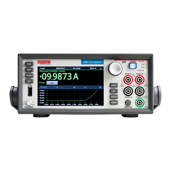
Page 17: Touchscreen Display Overview
The following text describes some of the most commonly used screens. For more detail and descriptions of all the screens, see the Model 2461 Reference Manual. For detail about an option, select it and press the HELP key to read a brief description of the option. - Page 18 The bottom half of the display is the swipe screen area, which Examples of the SETTINGS and GRAPH swipe screens are shown contains the following additional screens: below. SOURCE swipe screen: Displays the source settings. When the In the SETTINGS swipe screen shown here, the Auto Zero feature is turned on.
-
Page 19: Enter And Exit Keys
In the GRAPH swipe screen shown here, you can view the ENTER and EXIT keys measurements as they occur. To see a full-screen graph, touch the The ENTER key selects a highlighted option. In most cases, it graph icon on the right side of the swipe screen header bar to go to opens a menu or dialog box that allows you to make settings for that the Graph screen. -
Page 20: Menu Screen Overview
Menu screen overview From this screen, you can select source, measure, graphing, trigger, scripting, and system setup menus. These menus allow you to choose When you press the MENU key on the front panel, the Menu screen options to set up your instrument to meet the needs of your is displayed. -
Page 21: Quick Setup Options
Carefully consider and configure the appropriate output-off measurement resolution and measurement speed. state, source, and limits before connecting the Model 2461 to a device that can deliver energy, such as other voltage sources, Choose from a selection of Quick Setups that automatically make batteries, capacitors, or solar cells. - Page 22 HELP FUNCTION You can display help screens for the menu items and buttons. The The FUNCTION key opens the FUNCTION selection dialog help screens give a brief description of the option that the menu or box, which allows you to select the source, measure, and digitize button sets, and remote commands related to the setting.
-
Page 23: Connections For Testing
The example in this guide shows you how to make connections to the front panel and short the connections. For this example, you can make the connections with the insulated banana cables that are supplied with the Model 2461, the Keithley Instruments Model 8608 Safety Clip Lead Set. NEED 1. -
Page 24: Verify Measurement Operation
Verify measurement operation The following steps provide a quick way to verify that the instrument is operating correctly. To verify measurement operation: 1. Turn the instrument on. 2. On the front panel, press the HOME key. 3. Press the FUNCTION key. 4. - Page 25 The voltage measurements appear in the Measure Voltage area of the Home screen. To save the data to a USB flash drive: 1. Insert a USB flash drive into the front panel USB connector. 2. Press the MENU key. 3. Under Measure, select Reading Buffers. 4.
- Page 26 To view the measurements on the front-panel graph: 1. Press the MENU key. 2. Under Views, select Graph. You can swipe and use pinch and zoom to change the view of data on the graph. You can also adjust the graph settings using the options in the Data and Scale tabs.
- Page 28 You cannot combine the command sets. Verify the connections from the instrument to the test fixture. Also As delivered from Keithley Instruments, the Model 2461 is set to check the connections from the DUT to the test fixture socket. work with the SCPI command set.
-
Page 29: Next Steps
NPLCs. When you change the measure function to voltage, the Model 2461 User Manual: Contains basic information about the NPLC value changes to the value that was last set for the voltage instrument, plus application-based examples that will help measure function.
Need help?
Do you have a question about the 2461 and is the answer not in the manual?
Questions and answers