
Related Manuals for HYOSUNG TE 450


Summary of Contents for HYOSUNG TE 450
- Page 1 TE 450 ATV (Rapier 450) ServiceManual Max MC Import AB Mjölnarevägen 8 330 15 Bor Sverige Tel.: 0370-658570 Telefax 0370-658370 Org.nr. 556626-8198 www.maxmc.se info@maxmc.se www.hyosung.dk/se...
- Page 2 HYOSUNG vehicles. Without such knowledge and skills, you should not attempt servicing by relying on this manual only. Instead, please contact your nearby authorized HYOSUNG motorcycle dealer. � COPYRIGHT HYOSUNG MOTORS & MACHINERY INC. 2007.
- Page 3 HOW TO USE THIS MANUAL TO LOCATE WHAT YOU ARE LOOKING FOR : 1. The text of this manual is divided into sections. 2. As the title of these sections is listed on the previous page as GROUP INDEX, select the section where you are looking for. 3.
- Page 4 SYMBOL Listed in the table below are the symbols indicating instructions and other information necessary for servicing and meaning associated with them respectively. SYMBOL DEFINITION SYMBOL DEFINITION Torque control required. Apply THREAD LOCK “1324” . Data beside it indicates specified torque. Apply oil.
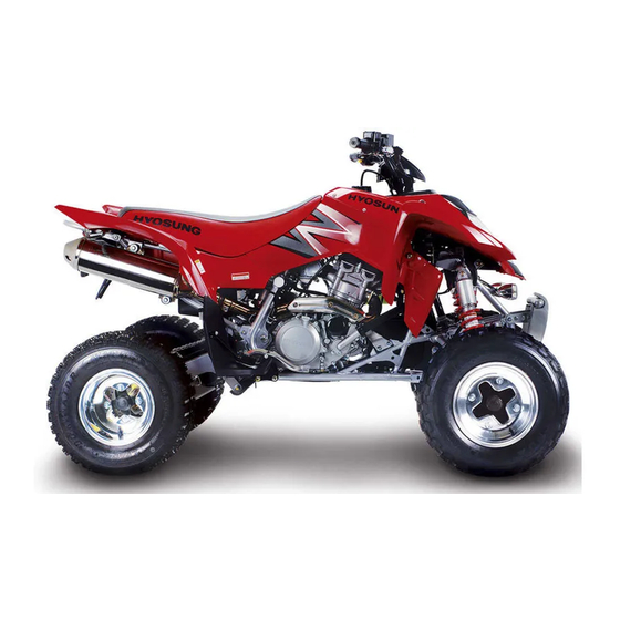
- Page 5 NOTE Difference between photographs and actual vehicles depends on the markets.
-
Page 6: Table Of Contents
GENERAL INFORMATION CONTENTS INFORMATION LABELS ………………………………………………… 1 - 1 GENERAL PRECAUTIONS …………………………………………… 1 - 2 SERIAL NUMBER LOCATION ………………………………………… 1 - 3 FUEL, OIL AND ENGINE COOLANT RECOMMENDATIONS …… 1 - 4 BREAK-IN PROCEDURES ……………………………………………… 1 - 6 EXTERIOR ILLUSTRATION ……………………………………………... - Page 7 1-1 GENERAL INFORMATION WARNING / CAUTION / NOTE Please read this manual and follow its instructions carefully. To emphasize special information, the symbol and the words WARNING, CAUTION and NOTE have special meanings. Pay special attention to the messages highlighted by these signal words. WARNING Indicates a potential hazard that could result in death or injury.
-
Page 8: General Precautions
WARNING � � If parts replacement is necessary, replace the parts with HYOSUNG Genuine Parts or their equivalent. � � When removing parts that are to be reused, keep them arranged in an orderly manner so that they may be reinstalled in the proper order and orientation. -
Page 9: Serial Number Location
1-3 GENERAL INFORMATION SERIAL NUMBER LOCATION The frame serial number or V.I.N. (Vehicle Identification Number) is stamped on the right side of the frame pipe. The engine serial number is stamped on the left downside of the crankcase assembly. These numbers are required especially for registering the machine and ordering spare parts. ◉... -
Page 10: Fuel, Oil And Engine Coolant Recommendations
GENERAL INFORMATION 1-4 FUEL, OIL AND ENGINE COOLANT RECOMMENDATIONS ◉ ◉ FUEL Gasoline used should be graded 91 octane (Research Method) or higher. An unleaded gasoline type is recom- mended. ◉ ◉ ENGINE OIL ▣ ▣ ENGINE OIL SPECIFICATION Classification system Grade 20W50 15W40 15W50... - Page 11 Hyosung recommends the use of HYOSUNG COOLANT anti-freeze/engine coolant. If this is not available, use an equivalent which is compatible with an aluminum radiator.
-
Page 12: Break-In Procedures
GENERAL INFORMATION 1-6 BREAK-IN PROCEDURES During manufacture only the best possible materials are used and all machined parts are finished to a very high standard but it is still necessary to allow the moving parts to “BREAK-IN” before subjecting the engine to maximum stresses. -
Page 13: Exterior Illustration
1-7 GENERAL INFORMATION EXTERIOR ILLUSTRATION 290mm 1,265mm (WHEEL BASE) 1,810mm (LENGTH) -
Page 14: Specifications
GENERAL INFORMATION 1-8 SPECIFICATIONS ◉ ◉ DIMENSIONS AND DRY MASS I T E M Overall length 1,810 mm (71.3 in) Overall width 1,160 mm (45.7 in) Overall height 1,165 mm (45.9 in) Wheelbase 1,265 mm (49.8 in) Ground clearance 290 mm (11.4 in) Dry mass 220 kg (485 lbs) ◉... - Page 15 1-9 GENERAL INFORMATION ◉ ◉ CHASSIS I T E M Front suspension Independent, double wishbone, coil spring and oil damped Rear suspension Swingarm type, coil spring and oil damped Steering angle 37°(right & left) Caster 7.3° Trail 34 mm (1.34 in) Toe-in [when apply to a load 75 kg (165 lbs)] 0 ~ 5 mm (0 ~ 0.2 in) Camber...
- Page 16 PERIODIC MAINTENANCE CONTENTS PERIODIC MAINTENANCE SCHEDULE ………………………… 2 - 1 PERIODIC MAINTENANCE CHART …………………………………… 2 - 1 LUBRICATION POINTS ………………………………………………… 2 - 2 MAINTENANCE PROCEDURES …………………………………… 2 - 3 AIR CLEANER …………………………………………………………… 2 - 3 EXHAUST PIPE NUTS AND MUFFLER BOLTS ……………………… 2 - 4 VALVE CLEARANCE ……………………………………………………...
-
Page 17: Periodic Maintenance Schedule
2-1 PERIODIC MAINTENANCE PERIODIC MAINTENANCE SCHEDULE The chart below lists the recommended intervals for all the required periodic service work necessary to keep the vehicle operating at peak performance and economy. CAUTION More frequent servicing should be performed on vehicles that are used under severe conditions. PERIODIC MAINTENANCE CHART ▣... -
Page 18: Lubrication Points
PERIODIC MAINTENANCE 2-2 LUBRICATION POINTS Proper lubrication is important for smooth operation and long life of each working part of the vehicle. Major lubrication points are indicated below. ① ② ④ ③ ⑤ ⑥ ① ④ Clutch lever holder Front brake lever holder ②... -
Page 19: Maintenance Procedures
: do not twist or wring the element or it will tear. ● Immerse the element in HYOSUNG genuine oil �, and then squeeze out the excess oil leaving the element slightly wet. -
Page 20: Exhaust Pipe Nuts And Muffler Bolts
PERIODIC MAINTENANCE 2-4 CAUTION � � Inspect the air cleaner element for tears. A torn element must be replaced. � � If driving under dusty conditions, clean the air cleaner element more frequently. The surest way to accelerate engine wear is to operate the engine without the element or with torn ele- ment. -
Page 21: Valve Clearance
2-5 PERIODIC MAINTENANCE VALVE CLEARANCE Inspect Interval Inspect Initially at 1 month and Every 6 months thereafter. Excessive valve clearance results in valve noise and insufficient valve clearance results in valve damage and reduced power. Check the intake and exhaust valve clearances at the distances indicated above and adjust the valve clearances to specification, if necessary. - Page 22 PERIODIC MAINTENANCE 2-6 ● Remove the cylinder head cover. The valve clearance specification is different for both intake and exhaust valves. Valve clearance adjustment must be checked and adjusted : 1) at the time of periodic inspection, 2) when the valve mechanism is serviced, and 3) when the camshafts are removed for servicing.
- Page 23 2-7 PERIODIC MAINTENANCE ● If the clearance is out of specification, first remove the cam chain tension adjuster, camshaft housing, camshaft. To install the tappet shim at original position, record the shim NO. and clearance to present by “A” , “B” , “C” , “D” mark on the cylinder head. Select the tappet that agree with tappet clearance (vertical line) and shim NO.(horizontal line) as refer to the tappet shim selection chart.
-
Page 24: Spark Plug
PERIODIC MAINTENANCE 2-8 SPARK PLUG Inspect Interval Inspect Every 6 months. Replace Every 18 months. ● Disconnect the spark plug cap ① and remove the spark plug. TYPE SPARK PLUG SPECIFICATION ① Hot type CR7E Standard type CR8E Cold type CR9E ▣... -
Page 25: Fuel Hose
2-9 PERIODIC MAINTENANCE CAUTION To avoid damaging the cylinder head threads ; first, finger tighten the spark plug, and then tight- en it to the specified torque using the spark plug wrench. ● Insert the spark plug and finger tighten it to the cylinder head and then tighten it to the specified torque. -
Page 26: Engine Oil And Oil Filter
PERIODIC MAINTENANCE 2-10 ● Connect the engine tachometer to the high-ten- sion cord. ● Start the engine and set the engine idle speed between 1,300 and 1,500 rpm by turning the throt- tle stop screw ① . Engine idle speed 1,300 ~ 1,500 rpm Engine tachometer : 09900-26006 ①... -
Page 27: Engine Oil Hoses
2-11 PERIODIC MAINTENANCE CAUTION � Necessarily, confirm and clean the oil strainer � � when replace the engine oil (specially, when first replacement). CAUTION More frequent servicing may be performed on vehicle that are used under severe conditions. ▣ ▣ OIL FILTER REPLACEMENT ●... -
Page 28: Engine Coolant
PERIODIC MAINTENANCE 2-12 ENGINE COOLANT Inspect Interval Replace Every 2 years. � ▣ ▣ ENGINE COOLANT CHECK ● Check the engine coolant level by observing the upper � and lower � lines on the engine coolant reservoir tank. � ● If the level is below the lower line, add engine coolant until the level reaches the upper line. -
Page 29: Radiator Hoses
2-13 PERIODIC MAINTENANCE 5. Install the radiator cap securely. 6. After warming up and cooling down the engine several times, add the engine coolant until the level is between the upper and lower lines on the engine coolant reservoir tank. CAUTION Repeat the above procedure several times and make sure the radiator is filled with the engine... -
Page 30: Brakes
PERIODIC MAINTENANCE 2-14 ● If not adjust by the adjuster �, loosen the clutch cable adjuster lock nut �. ● Turn the clutch cable adjuster � in or out to pro- vide the specified play. ● After adjustment, tighten the lock nut �. ●... - Page 31 2-15 PERIODIC MAINTENANCE ● Remove the rear master cylinder pin. ● Turn the adjuster � in or out until the pedal play � to the specification, after loosening the lock nut �. � ● Make sure to tighten the lock nut � securely. Brake pedal play �...
-
Page 32: Brake Fluid
PERIODIC MAINTENANCE 2-16 ● Tighten the parking brake cable adjuster lock nut �, �. ● Then turn the parking brake adjuster � 1/8 ~ 1/4 back. ● Tighten the parking brake adjuster lock nut � while holding the parking brake adjuster � in position. - Page 33 2-17 PERIODIC MAINTENANCE ▣ ▣ AIR BLEEDING OF THE BRAKE FLUID CIRCUIT Air trapped in the brake fluid circuit acts like a cush- ion to absorb a large proportion of the pressure developed by the master cylinder and thus interferes with the full braking performance of the brake caliper.
-
Page 34: Brake Hoses
PERIODIC MAINTENANCE 2-18 BRAKE HOSES Inspect Interval Inspect Every 6 months. Replace Every 4 years. Check the brake hoses for leakage, crack, wear and damage. If any damages are found, replace the brake hoses with new ones. TIRES Inspect Interval Inspect Every 3 months. -
Page 35: Steering
2-19 PERIODIC MAINTENANCE STEERING Inspect Interval Inspect Initially at 1 month and Every 3 months thereafter. Steering system should be adjusted properly for smooth manipulation of the handlebar and safe run- ning. ▣ ▣ TOE-IN ● Place the vehicle on level ground. ●... -
Page 36: Drive Chain
PERIODIC MAINTENANCE 2-20 DRIVE CHAIN Inspect Interval Inspect drive chain each time the vehicle is ridden. Visually check the drive chain for the possible defects listed below. (Support the vehicle by a jack and a wooden block, turn the rear wheel slowly by hand with the transmis- sion shifted to Neutral.) �Loose pins �Excessive wear... - Page 37 2-21 PERIODIC MAINTENANCE ● Count out 21 pins (20 pitches) on the chain and measure the distance between the two points. If the distance exceeds the service limit, the chain must be replaced. Service limit Drive chain 20-pitch length 319.4 mm (12.58 in) ▣...
- Page 38 Some drive chain lubricants contain solvents and additives which could damage the O-rings in your chain. Use Hyosung chain lube or an equivalent that is specifically intended for use with O-ring chains. ● After washing and drying the chain, oil it with a engine oil or chain lubricating oil.
-
Page 39: Suspensions
2-23 PERIODIC MAINTENANCE SUSPENSIONS Inspect Interval Inspect Every 6 months. ● Support the vehicle with a jack or wooden blocks. ● Remove the front and rear wheels. (Refer to page 7-8) ● Inspect the suspension arm, bearing and bushing for scratches, wear, or damage. If any damages are found, replace the suspension arm, bearing or bushing with a new one. -
Page 40: Compression Pressure
PERIODIC MAINTENANCE 2-24 COMPRESSION PRESSURE Low compression pressure can indicate some of the The compression pressure reading of a cylinder is a following conditions : good indicator of its internal condition. ● Excessively worn cylinder wall The decision to overhaul the cylinder is often based ●... -
Page 41: Oil Pressure
2-25 PERIODIC MAINTENANCE OIL PRESSURE Check the engine oil pressure periodically. This will give a good indication of the condition of the moving parts. Standard Oil pressure 1.0 ~ 3.0 ㎏ / ㎠ (at 60 ℃∙3,000 rpm) If the oil pressure is lower or higher than the specification, the following causes may be considered. ▣... - Page 42 ENGINE CONTENTS ENGINE REMOVAL AND REMOUNTING ………………………… 3 - 1 ENGINE REMOVAL ……………………………………………………… 3 - 1 ENGINE REMOUNTING ………………………………………………… 3 - 6 ENGINE DISASSEMBLY ………………………………………………… 3 - 9 ENGINE COMPONENT INSPECTION AND SERVICE ……… 3 - 21 CYLINDER HEAD ………………………………………………………… 3 - 21 CYLINDER …………………………………………………………………...
-
Page 43: Engine Removal And Remounting
3-1 ENGINE ENGINE REMOVAL AND REMOUNTING ENGINE REMOVAL Before taking the engine out of the frame, wash the engine using a suitable cleaner. Engine removal is sequentially explained in the fol- lowing steps. ● Drain engine coolant. (Refer to page 2-12) ①... - Page 44 ENGINE 3-2 ● Remove the fuel tank. (Refer to page 4-1) ● Disconnect the spark plug cap ① , oil tank over- flow hose ② and breather hose ③ . ② ③ ① ● Remove the engine coolant inlet hose ④ and dis- connect the outlet hose ⑤...
- Page 45 3-3 ENGINE ● Remove the carburetor with throttle cable. ● Disconnect the starter motor lead wire ① ground lead wire ② . ① ② ● Remove the engine sprocket cover.
- Page 46 ENGINE 3-4 ● Remove the clutch cable bracket ① . ③ ● Disconnect the clutch cable ② end out of the clutch lever. ● Disconnect the clutch cable ② end out of the clutch release arm. ② ● Remove the clutch release arm ③ . ①...
- Page 47 3-5 ENGINE ● Loosen the muffler connecting bolt ① . ● Remove the muffler mounting bolts ② . ② ① ● Remove the exhaust pipe nuts ③ . ● Remove the muffler. ● Remove the radiator ④ . ② ③ ④...
-
Page 48: Engine Remounting
ENGINE 3-6 ENGINE REMOUNTING Remount the engine in the reverse order of engine removal. Pay attention to the following points : 66 N ∙ m (6.6 kgf∙ m) 66 N ∙ m (6.6 kgf∙ m) 66 N ∙ m (6.6 kgf∙ m) 66 N ∙... - Page 49 3-7 ENGINE ● Tighten the exhaust pipe nuts �, muffler mount- ing bolts � and connecting bolt � to the specified torque. Exhaust pipe nut : 23 N∙ ∙ m (2.3 kgf∙ ∙ m) Muffler mounting bolt : 23 N∙ ∙ m (2.3 kgf∙ ∙ m) Muffler connecting bolt �...
- Page 50 ENGINE 3-8 ● After installing the engine, route the wiring har- ness, cables and hoses properly. (Refer to page 8-26 to 8-31) ● Adjust the following items. �Engine oil Refer to page 2-1 ∙∙∙∙∙∙∙∙∙∙∙∙∙ Necessary amount of engine oil Oil change 2,500 ㎖...
-
Page 51: Engine Disassembly
3-9 ENGINE ENGINE DISASSEMBLY ● Remove the starter motor ① . ● Remove the spark plug. ① ● Remove the thermostat cover ② and 2nd pipe ③ . ③ ② ● Remove the thermostat ④ . ④... - Page 52 ENGINE 3-10 ● Remove the cam chain tension adjuster bolt ① . ① ● Remove the cam chain tension adjuster ② . ② ● Remove the cylinder head cover bolts in diagonal stages, and then remove the cylinder head cover. ●...
- Page 53 3-11 ENGINE ● Turn the magneto rotor until the “T” line on the magneto rotor is aligned with the triangle mark on the crankcase. NOTE Before removing the camshaft housing, the piston must be at TDC of the compression stroke. ●...
- Page 54 ENGINE 3-12 ● Remove the cylinder head base bolts, and then remove the cylinder head. NOTE If the cylinder head does not come off easily, lightly tap it using a plastic hammer. ● Remove the cylinder head gasket ① and dowel ①...
- Page 55 3-13 ENGINE ● Place a clean rag over the cylinder base to pre- vent the piston pin circlip from dropping into the crankcase. ● Remove the piston pin circlip. ● Draw out the piston pin and remove the piston. ● Remove the magneto cover ① . ①...
- Page 56 ENGINE 3-14 NOTE When remove or inspect the clutch drive and driv- en plate, remove only the clutch pressure cover � � . ● Remove the dowel pins ① and gasket ② . ② ① ① ● Loosen the clutch spring mounting bolts working in diagonal stages.
- Page 57 3-15 ENGINE ● Remove the clutch push piece ① , push rod ② . ① , ② ● Flatten the clutch sleeve hub washer ③ . ③ ① ③ ② ● Hold the clutch sleeve hub using the special tool, ④...
- Page 58 ENGINE 3-16 ● Remove the coller ① . ① ● Remove the oil pipe ② . ② ● Remove the oil pump driven gear ③ by removing ③ the circlip ④ . ④ ● Remove the oil pin ⑤ and oil pump assembly. ⑤...
- Page 59 3-17 ENGINE ● Remove the gearshift shaft ① by removing the circlip ② . ① ② ② ● Remove the gearshift cam stopper ③ . ③ ● Loosen the gearshift cam plate bolt ④ . ● Remove the gearshift cam plate. ④...
- Page 60 ENGINE 3-18 ● Remove the primary drive gear ① . ① ● With the magneto rotor held immovable using the special tool, loosen the rotor nut. Conrod holder : 09910-20115 ● Remove the magneto rotor using the special tool. Rotor remover : 09930-30164 CAUTION Do not hit the magneto rotor with a hammer, oth- erwise the rotor may be damaged.
- Page 61 3-19 ENGINE ● Remove the cam chain ① and cam chain ten- ④ ③ sioner ② . ● Remove the starter idle shaft ③ and starter idle ② gear ④ . ① ● Remove the gear position switch ⑤ . ●...
- Page 62 ENGINE 3-20 ● Separate the crankcase using the special tool. Crankcase separator : 09920-13120 NOTE Fit the crankcase separator, so that the tool arms parallel the side of the crankcase. ● Remove the dowel pins ① . ① ● Remove the gearshift fork shafts ② , gearshift ②...
-
Page 63: Engine Component Inspection And Service
3-21 ENGINE ● Remove the crankshaft from the crankcase using the special tool. Crankcase separator : 09920-13120 ENGINE COMPONENT INS- PECTION AND SERVICE CAUTION ① ① Identify the position of each removed part. Organize the parts in their respective group (for example, exhaust or intake) so that they can be installed in their original positions. - Page 64 ENGINE 3-22 ● Remove the valve spring retainer ① , inner valve spring ② and outer valve spring ③ . ● Remove the valve ④ from the other side. ① ● Remove the oil seal ⑤ with long-nose pliers. ② ●...
- Page 65 3-23 ENGINE ● Install the valve spring retainer by pressing down ③ ② the spring using the valve spring compressor. Fit the cotter halves to the stem end and release the lifter to allow the cotter ① to wedge between the retainer and the valve stem.
- Page 66 ENGINE 3-24 ▣ ▣ VALVE STEM RUNOUT Check the valve stem for abnormal wear or bend. Support the valve using a V-blocks and measure the valve stem runout using the dial gauge, as shown. If the service limit is exceeded or abnormal condition exists, replace the valve with a new one.
- Page 67 3-25 ENGINE ▣ ▣ VALVE HEAD RADIAL RUNOUT Support the valve using a v-block and measure the valve head radial runout using the dial gauge, as shown. If the runout exceeds the service limit, replace the valve with a new one. Service limit Valve head radial Cylinder head...
- Page 68 ENGINE 3-26 ▣ ▣ VALVE SPRING The force of the coil spring keeps the valve seat tight. A weakened spring results in reduced engine power output and often accounts for the chattering noise coming from the valve mechanism. Check the valve springs for proper strength by mea- suring their free length and also by the force required to compress them.
- Page 69 3-27 ENGINE ▣ ▣ CAMSHAFT JOURNAL WEAR Determine whether or not each journal is worn down to the limit by measuring the oil clearance with the camshaft installed in place. ● Use the plastigauge to read the clearance at the widest portion, which is specified as follows : Service limit Camshaft journal...
-
Page 70: Cylinder
ENGINE 3-28 CYLINDER ▣ ▣ CYLINDER DISTORTION Check the gasketed surface of the cylinder for distor- tion using a straightedge and thickness gauge, taking a clearance reading at several places as indicated. If the largest reading at any position of the straight- edge exceeds the limit, replace the cylinder. -
Page 71: Piston And Piston Ring
3-29 ENGINE ▣ ▣ CAM CHAIN AND CAM CHAIN GUIDE Check the cam chain for wear, damage and kinked or binding links. If any defects are found, replace it with a new one. Check the cam chain guide for wear and damage. If it is found to be damaged, replace it with a new one. - Page 72 ENGINE 3-30 ▣ ▣ PISTON PIN DIAMETER INSPECTION Using a micrometer, measure the piston pin outside diameter at three position, both the ends and the center. If any of the measurements is founds less than the service limit, replace the pin with a new one. Service limit Piston pin diameter 18.980 mm (0.7472 in)
-
Page 73: Conrod
3-31 ENGINE ▣ ▣ PISTON RING-TO-GROOVE CLEAR- ANCE INSPECTION Remove carbon deposit both from the piston ring and its groove. Fit the piston ring into the groove. With the ring com- pressed and lifted up, measure the clearance on the bottom side of the ring using a thickness gauge. -
Page 74: Crankshaft
ENGINE 3-32 ▣ ▣ CONROD DEFLECTION INSPECTION Wear on the big end of the conrod can be estimated by checking the movement of the small end of the rod. Turn the conrod and see if it moves smoothly without play and noise. This method can also be used to check the extent of wear on the parts of the conrod’... -
Page 75: Crank Balancer And Balancer Drive Gear
3-33 ENGINE CRANK BALANCER AND BALANCER DRIVE GEAR ▣ ▣ DISASSEMBLY ● Disassemble the crank balancer and balancer drive gear as shown in the illustration. ▣ ▣ REASSEMBLY Reassemble the crank balancer and balancer drive gear in the reverse order of disassembly. - Page 76 ENGINE 3-34 ◉ ◉ STARTER CLUTCH Install the starter driven gear onto the starter clutch and turn the starter driven gear by hand(the gear turns in only one direction). The starter driven gear should turn smoothly. If excessive resistance is felt while turning the starter driven gear, inspect the starter clutch.
-
Page 77: Clutch
3-35 ENGINE CLUTCH ▣ ▣ CLUTCH DRIVE PLATES Measure the thickness and claw width of the clutch drive plates using a vernier calipers. If a clutch drive plate is not within the service limit, replace the clutch plates as a set. Standard Clutch drive plate... -
Page 78: Oil Pump
ENGINE 3-36 OIL PUMP ① ● Remove the outer rotor ① , inner rotor ② and pin ③ . Inspect the outer rotor ① and inner rotor ② for any scratches or other damage. If any damages are found, replace them with new ones. -
Page 79: Transmission
3-37 ENGINE TRANSMISSION ▣ ▣ DISASSEMBLY Disassemble the transmission gears as shown. - Page 80 ENGINE 3-38 ▣ ▣ INSPECTION ◈ GEAR-SHIFTING FORK Using a thickness gauge, check the clearance between the groove of its gear and shifting fork. The clearance for each of the three shifting forks plays an important role in the smoothness and posi- tiveness of shifting action.
- Page 81 3-39 ENGINE ▣ ▣ REASSEMBLY Reassemble the transmission in the reverse order of disassembly. Pay attention to following points : NOTE Before installing the gears, coat lightly engine oil to the inner surface of each gear and bushing. CAUTION � � Never reuse a circlip. After a circlip has been Thrust removed from a shaft, it should be discarded and a new circlip must be installed.
-
Page 82: Crankcase
ENGINE 3-40 ▣ ▣ TRANSMISSION GEARS AND RELATED PARTS CRANKCASE ▣ ▣ OIL STRAINER CAP ● Remove the oil strainer cap. - Page 83 3-41 ENGINE ● Remove the oil strainer screw. ● Clean the oil strainer using compressed air. ▣ ▣ OIL PUMP DRIVE GEAR ● Remove the oil pump drive gear ① . ① ▣ ▣ BEARING INSPECTION play play Wash the bearing with a cleaning solvent and lubri- cate it with motor oil before inspection.
- Page 84 ENGINE 3-42 ▣ ▣ OIL SEAL INSPECTION Damage to the lip of the oil seal may result in leak- age of the engine oil. Inspect the oil seal for wear or damage. If any damages are found, replace the oil seal with a new one.
-
Page 85: Clutch Cover
3-43 ENGINE ▣ ▣ CLUTCH RELEASE CAMSHAFT ① ● Remove the clutch release camshaft ① . ① ● Install the clutch release camshaft correctly. CLUTCH COVER ▣ ▣ OIL FILTER ☞ Refer to page 2-11 ▣ ▣ WATER PUMP ☞ Refer to page 5-11... -
Page 86: Engine Reassembly
ENGINE 3-44 ENGINE REASSEMBLY Reassemble the engine in the reverse order of disassembly. Pay special attention to the following points : NOTE Apply engine oil to each running and sliding part before reassembling the engine. ◉ ◉ CRANKSHAFT ● Determine the width between the webs referring to the figure when rebuilding the crankshaft. - Page 87 3-45 ENGINE ◉ ◉ GEARSHIFT CAM, FORK AND REVERSE LOCK SHAFT ① ⑤ ② ④ ③ ⑤ ● Install the gearshift forks into the gearshifting grooves in the correct position and direction. ① Gearshift fork No. 1 ② Gearshift fork No. 2 ③...
- Page 88 ENGINE 3-46 ◉ ◉ CRANKCASE ① ● Thoroughly remove the sealant material and oil stains on the mating surface of the right and left crankcases. ● Install the dowel pins ① to the crankcase. ● Apply engine oil to the conrod big end and to the transmission gears.
- Page 89 3-47 ENGINE ◉ ◉ GEAR POSITION SWITCH ③ ● Install the springs ① , contacts ② and new O-ring ③ . ● Install the gear position switch and tighten the bolts to the specified torque. Gear position switch bolt : 6.5 N∙ ∙ m (0.65 kgf∙ ∙ m) ①...
- Page 90 ENGINE 3-48 ◉ ◉ PRIMARY DRIVE GEAR AND WATER PUMP DRIVE GEAR ① ● Install the primary drive gear to the crankshaft ① . ● Install the water pump drive gear ② . ● Apply engine oil to the thread and inside surface of the nut.
- Page 91 3-49 ENGINE ● Install the gearshift shaft ① . ● Install the circlip ② . ① ② ② ◉ ◉ OIL PUMP ● Before mounting the oil pump, apply engine oil to the sliding surfaces of the oil pump case, outer rotor, inner rotor, and crankcase.
- Page 92 ENGINE 3-50 ◉ ◉ CLUTCH ● Install the clutch sleeve hub ① , lock washer ② . ① ② ● Hold the clutch sleeve hub using the special tool, and then tighten the clutch sleeve hub nut to the specified torque. Clutch sleeve hub nut : 90 N∙...
- Page 93 3-51 ENGINE ● Bend the tongue of the washer ① securely. ② , ③ ● Install the push rod ② , clutch push piece ③ . ① ③ ① ② ● Install the clutch drive plate NO. 2 �. � �...
- Page 94 ENGINE 3-52 ● Install the dowel pins ① and new gasket ② . ② ① CAUTION Use a new gasket to prevent oil leakage. ① ● Tighten the clutch cover bolts securely. ◉ ◉ MAGNETO ROTOR COVER ③ ● Install the dowel pins and new gasket ③ . CAUTION Use a new gasket to prevent oil leakage.
- Page 95 3-53 ENGINE ◉ ◉ PISTON RING ● Install the oil ring first, the 2nd ring second, and ① the 1st ring last. NOTE � � The 1st ① ① and 2nd ② ② piston rings differ in shape. � � The 1st and 2nd piston rings should be ②...
- Page 96 ENGINE 3-54 ◉ ◉ PISTON AND CYLINDER ● Apply MOLY PASTE onto the piston pin and small end of the conrod. MOLY PASTE NOTE Install the piston with the punch mark ① ① on the piston head facing toward the exhaust side. ①...
- Page 97 3-55 ENGINE ● Install the cam chain guide ① . ② NOTE Make sure that the guide ① ① is inserted properly or binding of the cam chain and guide may result. ③ ● Install the dowel pins ② and new gasket ③ . ①...
- Page 98 ENGINE 3-56 NOTE Just before installing the camshaft into the cylin- der head, apply MOLY PASTE to the camshaft journals and cam faces. Also, apply engine oil to the camshaft housing. MOLY PASTE ● Place each camshaft into the correct position. ●...
- Page 99 3-57 ENGINE ③ 1st pin 15th pin ② ①...
- Page 100 ENGINE 3-58 ● Install the dowel pins ① . ● Place each camshaft housing and cam chain ① guide into the correct position. NOTE ① Camshaft housing marked “EX” are for the exhaust side and those marked “IN” are for the intake side.
- Page 101 3-59 ENGINE ◉ ◉ CAM CHAIN TENSION ADJUSTER ● Apply engine oil to the push rod. ● Unlock the ratchet mechanism and push the push rod ① all the way. ① ● Install the new gasket and cam chain tension adjuster to the cylinder.
- Page 102 ENGINE 3-60 ● Install the thermostat cover ① and 2nd pipe ② . ② ① ● Install the spark plug. ③ ● Install the starter motor ③ .
- Page 103 FUEL SYSTEM CONTENTS FUEL TANK ………………………………………………………………… 4 - 1 FUEL COCK ……………………………………………………………… 4 - 1 FUEL PUMP ………………………………………………………………… 4 - 2 CARBURETOR ……………………………………………………………… 4 - 3 CAUTION Gasoline must be handled carefully in an area well ventilated and away from fire or sparks.
-
Page 104: Fuel Tank
4-1 FUEL SYSTEM FUEL TANK ◉ ◉ REMOVAL WARNING ① Gasoline is highly flammable and explosive. Keep heat, sparks and flames away from gasoline. ● Remove the seat, side covers. (Refer to page 7-3~4) ● Remove the fuel tank mounting bolts ① . ●... -
Page 105: Fuel Pump
FUEL SYSTEM 4-2 ◉ ◉ REMOUNTING Remount the fuel cock in the reverse order of removal. CAUTION Tighten the fuel cock bolts evenly. FUEL PUMP ④ ◉ ◉ REMOVAL ● Remove the seat and fuel tank. ● Disconnect the fuel hoses ③ , ④ and vacuum hose ⑤... -
Page 106: Carburetor
4-3 FUEL SYSTEM CARBURETOR ◉ ◉ CONSTRUCTION... - Page 107 FUEL SYSTEM 4-4 ◉ ◉ LOCATION OF CARBURETOR I.D.NO. The carburetor I.D. is stamped on the location on the carburetor as shown in the right photo. ◉ ◉ REMOVAL ● Remove the left side cover. (Refer to page 7-4) ● Disconnect the fuel hose ① . ①...
- Page 108 4-5 FUEL SYSTEM ● Disconnect the throttle cable ① . ● Remove the O-ring ② . ① ② ◉ ◉ DISASSEMBLY ④ ● Remove the fuel hose ③ and air vent hoses ④ . ③ ● Remove the throttle stop screw ⑤ . ⑤...
- Page 109 FUEL SYSTEM 4-6 ● Remove the spring ① , along with the diaphragm assembly ② . ② ① ● Remove the jet needle holder ③ , spring ④ , E-ring ⑤ , ring ⑥ and jet needle ⑦ . ③ ④...
- Page 110 4-7 FUEL SYSTEM ● Remove the float chamber body ① . ① ● Remove the O-ring ② . CAUTION ② Replace the removed O-ring with a new one to prevent leakage of fuel. ● Remove the float pin ③ , float ④ and needle valve ⑤...
- Page 111 FUEL SYSTEM 4-8 ● Remove the main jet ① , jet holder ② and pilot jet ① , ② ③ . ③ ● Remove the pilot air jet ④ counting and tightening ④ the number of turn. NOTE Before removing the pilot air jet ④ ④ , its setting must be determined.
- Page 112 4-9 FUEL SYSTEM ◉ ◉ FLOAT HEIGHT ADJUSTMENT To check the float height, turn the carburetor upside � down. Measure the float height � while the float arm is just contacting the needle valve using a vernier calipers. Float height � � 13 mm (0.51 in) Vernier calipers : 09900-20101 ●...
- Page 113 FUEL SYSTEM 4-10 ● Align the hole ① of the diaphragm with passage- way on the carburetor body. NOTE When installing the diaphram, make sure the diaphram is seated at the concave section of the carburetor. ① ● Apply SUPER GREASE “A” to thread part of the throttle stop screw, then install the throttle stop screw to the carburetor.
- Page 114 COOLING SYSTEM CONTENTS ENGINE COOLANT ……………………………………………………… 5 - 1 COOLING CIRCUIT ……………………………………………………… 5 - 2 RADIATOR …………………………………………………………………… 5 - 2 COOLING FAN ……………………………………………………………… 5- 5 COOLING FAN THERMO-SWITCH ………………………………… 5- 6 WATER TEMPERATURE SWITCH …………………………………… 5 - 8 THERMOSTAT ……………………………………………………………… 5 - 9 WATER PUMP ………………………………………………………………...
-
Page 115: Engine Coolant
5-1 COOLING SYSTEM ENGINE COOLANT Anti-freeze density Freezing point -31 ℃ (-24 ℉ ) At the time of manufacture, the cooling system is filled with a 50 : 50 mixture of distilled water and -40 ℃ (-40 ℉ ) ethylene glycol anti-freeze. -55 ℃... -
Page 116: Cooling Circuit
COOLING SYSTEM 5-2 COOLING CIRCUIT ① Impeller ② Radiator cap ③ Radiator ④ Thermostat ⑤ Cooling fan thermo-switch ⑥ Water temperature switch RADIATOR ◉ ◉ REMOVAL ● Remove the front fender. (Refer to page 7-3) ● Drain engine coolant by removing the drain bolt ①... - Page 117 5-3 COOLING SYSTEM ● Disconnect reserve tank hose ① . ● Disconnect the cooling fan motor lead wire cou- pler. ① ● Remove the radiator by the mounting bolts. ◉ ◉ INSPECTION AND CLEANING Road dirt or trash stuck to the fins must be removed. Use of compressed air is recommended for this cleaning.
- Page 118 COOLING SYSTEM 5-4 Fins bent down or dented can be repaired by straightening them with the blade of a small screw- driver. ◉ ◉ INSPECTION OF WATER HOSE ● Remove the front fender. (Refer to page 7-3) Any water hose found in a cracked condition or flat- tened or water leaked must be replaced.
-
Page 119: Cooling Fan
5-5 COOLING SYSTEM COOLING FAN ◉ ◉ INSPECTION ● Remove the front fender. (Refer to page 7-3) ● Disconnect the cooling fan motor lead wire cou- pler and its thermo-switch lead wire coupler. Test the cooling fan motor for load current with an ammeter connected as shown in the illustration. -
Page 120: Cooling Fan Thermo-Switch
COOLING SYSTEM 5-6 COOLING FAN THERMO-SWITCH The cooling fan is secured behind the radiator by three bolts and is automatically controlled by the thermo-switch. The thermo-switch remains open when the temperature of the engine coolant is low, but closes when the tempera- ture reaches approximately 88 ℃... - Page 121 5-7 COOLING SYSTEM ◉ ◉ INSTALLATION Install the cooling fan thermo-switch in the reverse ① order of removal. Pay attention to the following points : ● Install a new O-ring ① and apply engine coolant to the O-ring. ● Tighten the cooling fan thermo-switch to the speci- fied torque.
-
Page 122: Water Temperature Switch
COOLING SYSTEM 5-8 WATER TEMPERATURE SWITCH ◉ ◉ REMOVAL ● Remove the front fender. (Refer to page 7-3) ① ● Drain engine coolant. (Refer to page 2-12) ● Disconnect the water temperature switch lead wire coupler. ● Remove the water temperature switch ① . ◉... -
Page 123: Thermostat
5-9 COOLING SYSTEM THERMOSTAT ◉ ◉ REMOVAL ● Remove the front fender. (Refer to page 7-3) ● Drain engine coolant. (Refer to page 2-12) ● Place a rag under the thermostat case. ● Remove the thermostat case cap. ● Remove the thermostat ① . ①... - Page 124 COOLING SYSTEM 5-10 ● Keep on heating the water to raise its tempera- ture. ● Just when the water temperature reaches speci- fied value, the thermostat valve should have lifted by at least 8.0 mm (0.32 in). � Standard Thermostat valve lift Over 8.0 mm at 90 ℃...
-
Page 125: Water Pump
5-11 COOLING SYSTEM WATER PUMP ◉ ◉ REMOVAL AND DISASSEMBLY ● Drain engine coolant. (Refer to page 2-12) ● Drain engine oil. (Refer to page 2-10) WARNING � � Do not open the radiator cap when the engine is hot, as you may be injured by escaping hot liquid or vapor. - Page 126 COOLING SYSTEM 5-12 ● Remove the circlip and water pump driven gear ① . ① ● Remove the pin ② and washer ③ . ③ ② ● Remove the water pump case ④ from the clutch cover. ④ ● Remove the O-rings ⑤ . ⑤...
- Page 127 5-13 COOLING SYSTEM ● Remove the E-ring ① from the impeller shaft. ① ● Remove the impeller ② from the other side. ② ● Remove the bearing. NOTE If there is no abnormal noise, bearing removal is not necessary. ◉ ◉ INSPECTION ▣...
- Page 128 COOLING SYSTEM 5-14 ▣ ▣ BEARING CASE Visually inspect the bearing case for damage. Replace the water pump body if necessary. ▣ ▣ IMPELLER Visually inspect the impeller and its shaft for damage. ◉ ◉ REASSEMBLY AND INSTAL- LATION Install the water pump in the reverse order of removal.
- Page 129 5-15 COOLING SYSTEM ● Fix the impeller shaft with the E-ring ① . ● Fill the bearing with engine oil until engine oil comes out from the hole of the bearing housing. ① ● Apply engine coolant to the O-ring ② . ●...
-
Page 130: Oil Tank And Hoses
COOLING SYSTEM 5-16 OIL TANK AND HOSES ◉ ◉ CONSTRUCTION... - Page 131 5-17 COOLING SYSTEM REMOVAL ● Remove the front fender. (Refer to page 7-3) ● Drain engine coolant. (Refer to page 2-12) ● Remove the radiator. (Refer to page 5-2) ● Drain engine oil. (Refer to page 2-10) ● Remove the engine under cover ① . ①...
- Page 132 COOLING SYSTEM 5-18 ● Remove the oil tank. ◉ ◉ REMOUNTING Remount the oil tank and hoses in the reverse order of removal. Pay attention to the following points : ● Tighten the engine oil inlet hose union bolts ① the specified torque.
- Page 133 5-19 COOLING SYSTEM ● Install the new O-ring ① to the hoses. ② CAUTION ① Use the new O-rings to prevent engine coolant leakage. ● Install the gaskets ② . ● Apply engine oil to the O-ring and gaskets. ● Pour engine oil. (Refer to page 2-11) ②...
- Page 134 ELECTRICAL SYSTEM CONTENTS LOCATION OF ELECTRICAL COMPONENTS …………………… 6 - 1 IGNITION SYSTEM ………………………………………………………… 6 - 3 CHARGING SYSTEM ……………………………………………………… 6 - 7 STARTER SYSTEM ………………………………………………………… 6 - 9 SWITCHES …………………………………………………………………… 6 - 12 LAMPS ………………………………………………………………………… 6 - 14 BATTERY ………………………………………………………………………...
-
Page 135: Location Of Electrical Components
6-1 ELECTRICAL SYSTEM LOCATION OF ELECTRICAL COMPONENTS ① ② ③ ④ ① ② ③ Left handlebar switch Ignition coil Cooling fan motor relay ④ Head lamp relay ⑥ ⑦ ⑨ ⑩ ⑧ ⑪ ⑤ ⑤ ⑥ ⑧ Horn Magneto Igniter ⑦... - Page 136 ELECTRICAL SYSTEM 6-2 ⑭ ⑬ � ⑮ ⑫ ⑫ ⑬ ⑭ Battery Front brake lamp switch Cooling fan motor ⑮ Cooling fan thermo-switch � Water temperature switch � � � � � � Main fuse Rear brake lamp switch Starter motor...
-
Page 137: Ignition System
6-3 ELECTRICAL SYSTEM IGNITION SYSTEM IG. S/W FUSE BATTERY 12V 8Ah ◉ ◉ INSPECTION ▣ ▣ SPARK PLUG Clean the plug with a wire brush and pin. Use the pin to remove carbon, taking care not to damage the porcelain. ●... - Page 138 ELECTRICAL SYSTEM 6-4 ▣ ▣ MAGNETO Using the pocket tester, measure the resistance between the lead wires in the following table. If the resistance is not within the specified value, replace the stator coil, with a new one. Stator coil resistance Standard G-L 90 ~ 110 Ϊ...
- Page 139 6-5 ELECTRICAL SYSTEM ▣ ▣ IGNITION COIL ● Remove the front fender, side cover, fuel tank. (Refer to page 7-3 and 4-1) ● Pull out the spark plug. ● Place it on the cylinder head after installing it at the plug cap to obtain ground. ●...
- Page 140 ELECTRICAL SYSTEM 6-6 ▣ ▣ IGNITER ㏀ Using the pocket tester (R × 1 range), measure the resistance between the terminal in the following table. Pocket tester : 09900-25002 CAUTION � � Numberical value may differ a little according to the tester. �...
-
Page 141: Charging System
6-7 ELECTRICAL SYSTEM CHARGING SYSTEM Regulator / Rectifier IG. switch A. C generator ◉ ◉ INSPECTION ▣ ▣ CHARGING OUTPUT CHECK Start the engine and keep it running at 5,000 rpm. Using the pocket tester, measure the DC voltage between the battery terminal � and �... - Page 142 ELECTRICAL SYSTEM 6-8 ▣ ▣ MAGNETO NO-LOAD PERFORMANCE Disconnect the three lead wires from the magneto terminal. Start the engine and keep it running at 5,000 rpm. Using the pocket tester, measure the AC voltage between the three lead wires. If the voltage is under the specified value, replace the magneto with a new one.
-
Page 143: Starter System
6-9 ELECTRICAL SYSTEM STARTER SYSTEM ◉ ◉ STARTER SYSTEM DESCRIPTION Clutch lever Starter Starter position Ignition motor switch switch switch Fuse Starter relay Igniter This ATV can only start the engine with pulling the clutch lever. - Page 144 ELECTRICAL SYSTEM 6-10 ◉ ◉ STARTER MOTOR REMOVAL AND DISASSEMBLY ● Disconnect the starter motor lead wire. ● With loosening the bolts ① , remove the starter motor. ● Remove the starter motor. ① ◉ ◉ STARTER MOTOR INSPEC- TION ▣...
- Page 145 6-11 ELECTRICAL SYSTEM ◉ ◉ STARTER MOTOR REASSEMBLY Reassemble the starter motor. Pay attention to the following points : ● Reassembly the starter motor as shown in the illustration. ● Align the match mark ① on the housing with the ①...
-
Page 146: Switches
ELECTRICAL SYSTEM 6-12 SWITCHES Measure each switch for continuity using a tester. If any abnormality is found, replace the respective switch assemblies with new ones. Pocket tester : 09900-25002 IGNITION SWITCH HAZARD WARNING SWITCH ○ ○ ○ ○ ● LIGHT & DIMMER SWITCH STARTER SWITCH ○... -
Page 147: Lamps
6-13 ELECTRICAL SYSTEM LAMPS ◉ ◉ HEAD LAMP CAUTION If you touch the bulb with your bare hands, clean the bulb with a cloth moistened with alcohol or soapy water to prevent premature bulb failure. HEAD LAMP BULB REPLACE- ▣ ▣ MENT ●... - Page 148 ELECTRICAL SYSTEM 6-14 ◉ ◉ BRAKE / TAIL LAMP ▣ ▣ BRAKE / TAIL LAMP REPLACEMENT This ATV’s brake / tail lamp is LED(Light Emitting Diode) type. If any abnormal condition are found, replace the brake / tail lamp assembly. BRAKE / TAIL LAMP : LED type ◉...
- Page 149 6-15 ELECTRICAL SYSTEM ◉ ◉ COMBINATION METER Remove the combination meter. Disassemble the combination meter as shown in the illustration. ▣ ▣ INSPECTION Using the pocket tester, check the continuity between lead wires (Blue color coupler) in the following illus- tration.
-
Page 150: Battery
ELECTRICAL SYSTEM 6-16 BATTERY ◉ ◉ CAUTION OF BATTERY TREATMENT The battery needs attention generally as it occur flammability gas. If you don’t follow the instruction in the below, there may be a explosion and severe accident. Therefore, pay attention to the following points. ●... - Page 151 6-17 ELECTRICAL SYSTEM Seal ③ Pouring of battery electrolyte When insert the nozzles of the electrolyte container into the battery’s electrolyte filler holes, holding the container firmly so that it does not fall. Take precaution not to allow any fluid to spill. CAUTION The pouring of electrolyte may not be done if the electrolyte container is pushed slopely.
- Page 152 ELECTRICAL SYSTEM 6-18 ⑤ Separation of electrolyte container After confirming that you entered the electrolyte into battery completely, remove the electrolyte containers from the battery. CAUTION Draw the empty receptacle out slowly because there may be a chance remaining electrolyte vaporize. ⑥...
- Page 153 CHASSIS CONTENTS EXTERIOR PARTS ………………………………………………………… 7- 1 FRONT AND REAR WHEELS ………………………………………… 7 - 7 FRONT BRAKE ……………………………………………………………… 7-13 FRONT SUSPENSION …………………………………………………… 7 - 21 STEERING ……………………………………………………………………… 7 -30 REAR BRAKE ………………………………………………………………… 7 -41 REAR SHOCK ABSORBER ……………………………………………… 7-54 REAR SUSPENSION ………………………………………………………...
-
Page 154: Exterior Parts
7-1 CHASSIS EXTERIOR PARTS ◉ ◉ CONSTRUCTION... - Page 155 CHASSIS 7-2...
- Page 156 7-3 CHASSIS ◉ ◉ REMOVAL ▣ ▣ SEAT ● Remove the seat by pulling the lock release lever ① which is located behind the rear fender. ① ▣ ▣ FRONT FENDER ● Disconnect the head lamp coupler ② . ② ●...
- Page 157 CHASSIS 7-4 ● Remove the four steering head cover bracket bolts. ● Remove the front fender mounting bolts. ● Remove the front fender ① . ① ● Remove the side covers ② , left and right. ② ▣ ▣ FOOTREST MUDGUARD ●...
- Page 158 7-5 CHASSIS ▣ ▣ FOOTREST ● Remove the footrest mudguards. (Refer to page 7-4) ● Remove the footrests. ▣ ▣ REAR FENDER ① ● Remove the seat. (Refer to page 7-3) ● Remove the battery plate. ● Disconnect the battery lead wires ① . ●...
- Page 159 CHASSIS 7-6 ◉ ◉ REMOUNTING ③ ③ ① Remount the exterior parts in the reverse order of removal. Pay attention to the following points : ▣ ▣ FOOTREST ● Apply THREAD LOCK “1324” to the bolts ① tighten bolts to the specified torque. THREAD LOCK “...
-
Page 160: Front And Rear Wheels
7-7 CHASSIS FRONT AND REAR WHEELS ◉ ◉ CONSTRUCTION... - Page 161 CHASSIS 7-8 ◉ ◉ REMOVAL ▣ ▣ FRONT AND REAR WHEELS ● Place the vehicle on level ground. ● Support the vehicle with a jack or wooden block. ● Remove the wheel. ▣ ▣ FRONT WHEEL HUB ③ ① ● Remove the front wheel. (Refer to above) ●...
- Page 162 7-9 CHASSIS ▣ ▣ REAR WHEEL HUB ● Remove the rear wheel. ● Remove the cotter pin and loosen the wheel hub nut by applying the rear brake. ● Remove the wheel hub nut and washer. ● Remove the rear wheel hub ① . ①...
- Page 163 CHASSIS 7-10 ● Remove the hub bearing ① . CAUTION Do not reuse the removed bearings. ① ◉ ◉ REASSEMBLY AND REMOUNTING ▣ ▣ FRONT WHEEL HUB ● Apply SUPER GREASE “A” to the hub bearing. SUPER GREASE “A” GREASE ●...
- Page 164 7-11 CHASSIS ● Install the front disk to the front wheel hub. (Refer to page 7-18) ● Apply SUPER GREASE “A” to the front axle. SUPER GREASE “A” ● Install the wheel hub. ● Install the front brake caliper. (Refer to page 7-17) ●...
- Page 165 CHASSIS 7-12 ▣ ▣ FRONT WHEEL ● Install the front wheel. ● Tighten the wheel set nuts to the specified torque. Wheel set nut : 39.2~58.8 N∙ ∙ m (3.92~5.88 kgf∙ ∙ m) ◈ ON-ROAD type � NOTE When installing the front wheel, make sure that the arrow �...
-
Page 166: Front Brake
7-13 CHASSIS FRONT BRAKE ◉ ◉ CONSTRUCTION WARNING � � This brake system is filled with an ethylene glycol-based DOT4 brake fluid. Do not use or mix different types of fluid, such as silicone-based or petroleum-based brake fluids. � � Do not use any brake fluid taken from old, used or unsealed containers. Never reuse brake fluid left over from the last servicing or stored for a long periods. - Page 167 CHASSIS 7-14 ◉ ◉ BRAKE PAD REPLACEMENT ● Remove the front wheel. (Refer to page 7-8) ● Remove the brake caliper mounting bolts ① brake pad mounting pins ② . ② ① ● Remove the brake pads. CAUTION � � Do not operate the brake lever during or after brake pad removal.
- Page 168 7-15 CHASSIS ◉ ◉ BRAKE FLUID REPLACEMENT ● Place the vehicle on a level surface and keep the handlebar straight. ● Remove the master cylinder reservoir cap and diaphragm. ● Suck up the old brake fluid as much as possible. ●...
- Page 169 CHASSIS 7-16 ● Remove the brake pad spring ① and brake caliper ② holder ② . ① ● Using an air gun, push out the brake caliper pis- ton. WARNING � � Place a rag over the piston to prevent it from popping out and flying and keeping hand off the piston.
- Page 170 7-17 CHASSIS ◉ ◉ BRAKE CALIPER REASSEM- BLY AND REMOUNTING Reassemble and remount the brake caliper in the reverse order of removal and disassembly proce- dures and observe the following points. CAUTION � � Wash the brake caliper components with fresh brake fluid before reassembly.
- Page 171 CHASSIS 7-18 ◉ ◉ BRAKE DISK REMOVAL AND DISASSEMBLY ● Remove the front wheel. (Refer to page 7-8) ● Remove the front wheel hub. (Refer to page 7-8) ● Remove the brake disk. ◉ ◉ BRAKE DISK INSPECTION ● Remove the front wheel. (Refer to page 7-8) ●...
- Page 172 7-19 CHASSIS ◉ ◉ MASTER CYLINDER DISAS- ① SEMBLY ● Drain brake fluid out of the master cylinder. ● Disconnect the brake lamp switch lead wire cou- pler. ● Remove the union bolt ① . CAUTION Place a rag under the union bolt so that brake fluid can not contact the parts.
- Page 173 CHASSIS 7-20 ◉ ◉ MASTER CYLINDER INSPECTION Inspect the master cylinder bore for any scratches or other damage. Inspect the piston surface for any scratches or other damage. ◉ ◉ MASTER CYLINDER REASSE- MBLY AND REMOUNTING Reassemble and remount the master cylinder in the reverse order of removal and disassembly.
-
Page 174: Front Suspension
7-21 CHASSIS FRONT SUSPENSION ◉ ◉ CONSTRUCTION... - Page 175 CHASSIS 7-22 ◉ ◉ REMOVAL ● Remove the front wheel (Refer to page 7-8) ● Remove the front wheel hub. (Refer to page 7-8) ● Remove the brake caliper. (Refer to page 7-15) ● Remove the front disk cover ① . ①...
- Page 176 7-23 CHASSIS ● Remove the shock absorber lower mounting bolt ① . ● Remove the suspension arm assembly ② . ① ② ● Remove the shock absorber upper mounting bolt ③ . ● Remove the shock absorber ④ . ③ ③...
- Page 177 CHASSIS 7-24 ◉ ◉ INSPECTION AND DISASSEMBLY ▣ ▣ FRONT SHOCK ABSORBER Inspect the shock absorber for oil leakage or dam- age. If any damages are found, replace the front shock absorber with a new one. Inspect the bearings, spacers and dust seal for wear or damage.
- Page 178 7-25 CHASSIS ▣ ▣ SUSPENSION ARM PIVOT BEARING Inspect the dust seal lips and spacers for wear and damage. If any damages are found, replace them with new ones. Inspect the bearings for play. If excessive play is found, replace them with a new one. ▣...
- Page 179 CHASSIS 7-26 ◉ ◉ REASSEMBLY AND REMOUNTING ① ② UPPER ③ ③ ② Reassemble and remount the front suspension in the reverse order of removal and disassembly. Pay attention to the following points : ● Apply SUPER GREASE “A” to the dust seals, dust ①...
- Page 180 7-27 CHASSIS ● Tighten the suspension arm pivot nuts to the specified torque. Suspension arm pivot nut : 40~60 N∙ ∙ m (4.0~6.0 kgf∙ ∙ m) ● Install the front grip and the front shock absorber. ● Apply THREAD LOCK “1324” to the front shock absorber mounting bolts.
- Page 181 CHASSIS 7-28 NOTE When installing the tie rod end, install the washer ② ① ③ ① ① between the nut ② ② and steering knuckle ③ ③ . ◉ ◉ FRONT SUSPENSION SETTING ▣ ▣ SPRING PRE-LOAD ADJUSTMENT The front suspension spring pre-load is adjustable. This adjustment is performed by changing spring set length.
- Page 182 7-29 CHASSIS ▣ ▣ DAMPING FORCE ADJUSTMENT The compression and tension damping force are adjustable for rider’ s preference, rider’s weight and field condition. NOTE Do not turn the adjuster screws more than given position, or the adjuster may be damaged. 1.
-
Page 183: Steering
CHASSIS 7-30 STEERING ◉ ◉ CONSTRUCTION... - Page 184 7-31 CHASSIS ◉ ◉ REMOVAL ② ① ▣ ▣ HANDLEBAR ● Remove the front fender. (Refer to page 7-3) ● Remove the master cylinder assembly ① from the handlebar. (Refer to page 7-19) ● Remove the throttle lever case ② . ●...
- Page 185 CHASSIS 7-32 ▣ ▣ STEERING SHAFT AND TIE ROD ● Drain engine oil and coolant. (Refer to page 2-10 and 2-12) ● Remove the radiator assembly ① . (Refer to page 5-2) ① ● Disconnect the oil hoses ② and overflow hose ③ . ③...
- Page 186 7-33 CHASSIS ● Remove the cotter pin ① and steering shaft nut ② and washer ③ . ① CAUTION ③ Replace the removed cotter pins with new ones. ② ● Remove the O-ring ④ . ④ ● Remove the steering shaft holder cotter pin.
- Page 187 CHASSIS 7-34 ● Remove the steering shaft holder bolts. ● Remove the cable/hose guide and the steering ① shaft holder. ● Remove the steering shaft ① . ● Remove the bushing ② and the dust seal ③ from the steering shaft. ●...
- Page 188 7-35 CHASSIS ① Tie rod end ① ② Lock nut ④ ③ Lock nut ① ① ④ Tie rod ③ CAUTION ④ ② ③ The lock nuts ③ ③ with a narrow width have left- ① hand threads. ② ▣ ▣ TIE ROD END Inspect the tie rod ends for smooth movement.
- Page 189 CHASSIS 7-36 ◉ ◉ REASSEMBLY AND REMOUNTING Reassemble and remount the steering shaft in the reverse order of removal and disassembly. Pay attention to the following points : ▣ ▣ STEERING SHAFT ① ● Apply SUPER GREASE “A” to the O-ring, dust ②...
- Page 190 7-37 CHASSIS ● Tighten the steering shaft holder bolts to the spec- ified torque. Steering shaft holder bolt : 18~28 N∙ ∙ m (1.8~2.8 kgf∙ ∙ m) NOTE Make sure that the wiring harness, cables and brake hose routing are properly. (Refer to page 8-26 to 8-31) ●...
- Page 191 CHASSIS 7-38 CAUTION The lock nuts ① ① with a narrow width have left- hand threads. Forward ① ① ▣ ▣ OIL TANK AND RADIATOR ● Install the oil tank. (Refer to page 5-18) ● Reinstall the radiator assembly. (Refer to page 5-4) ●...
- Page 192 7-39 CHASSIS ● Install the speedometer ① . ① ● Install the handle switch box with the lug ② on the ③ switch half inserted into the hole ③ on the handle- bar. NOTE When installing the handlebar, make sure that the cable, wiring harness and brake hose routing are proper.
- Page 193 CHASSIS 7-40 ◉ ◉ TOE-IN ADJUSTMENT Adjust the toe-in as follows : ① ② ② ● Place the vehicle on level ground and set the han- ① dlebar straight. Make sure all the tires are inflated to the standard pressure. (Refer to page 2-18) ●...
-
Page 194: Rear Brake
7-41 CHASSIS REAR BRAKE ◉ ◉ CONSTRUCTION WARNING � � This brake system is filled with an ethylene glycol-based DOT 4 brake fluid. � � Do not use or mix different types of fluid such as silicone-based or petroleum-based brake fluids. �... - Page 195 CHASSIS 7-42 ◉ ◉ BRAKE PAD REPLACEMENT ● Flatten the lock washer ① , and then slightly ① loosen the pad mounting pins ② . ② ● Loosen the lock nut ③ and turn out the parking brake adjuster ④ several turns.
- Page 196 7-43 CHASSIS ● Tighten the caliper mounting bolts to the specified torque. Brake caliper mounting bolt : 18~28 N∙ ∙ m (1.8~2.8 kgf∙ ∙ m) ● Adjust the parking brake. (Refer to page 2-15) ◉ ◉ BRAKE FLUID REPLACEMENT ① ●...
- Page 197 CHASSIS 7-44 ◉ ◉ BRAKE CALIPER REMOVAL AND DISASSEMBLY ● Disconnect the parking brake cable by removing the lock nut ① and lever ② . ② ① ● Disconnect the brake hose ③ and allow the brake fluid to drain into a suitable receptacle. ●...
- Page 198 7-45 CHASSIS ● Loosen the caliper pin bolt ① , and then remove the caliper holder ② . ● Remove the caliper pin bolt ① . ② ① ● Place a rag over the brake caliper piston ③ to pre- vent the piston from popping out.
- Page 199 CHASSIS 7-46 ◉ ◉ BRAKE CALIPER REASSEM- BLY AND REMOUNTING ☞ Refer to page 7-17 Reassemble and remount the brake caliper in the reverse order of removal and disassembly. Pay attention to the following points : ▣ ▣ PISTON SEALS ●...
- Page 200 7-47 CHASSIS ● Tighten the caliper mounting bolts ① and brake hose union bolt ② . Brake caliper mounting bolt : 18~28 N∙ ∙ m (1.8~2.8 kgf∙ ∙ m) ② Brake hose union bolt : 40~60 N∙ ∙ m (4.0~6.0 kgf∙ ∙ m) NOTE ①...
- Page 201 CHASSIS 7-48 ● Connect the parking cable ① . ① ● Install the adjuster ② and the lock nut ③ . ● Adjust the parking brake. (Refer to page 2-15) ② ③ ◉ ◉ BRAKE DISK REMOVAL AND REMOUNTING ● Remove the rear wheel. (Refer to page 7-8) ●...
- Page 202 7-49 CHASSIS ◉ ◉ MASTER CYLINDER REMOVAL ⑥ AND DISASSEMBLY ⑧ ● Drain the brake fluid. (Refer to page 7-43) ① ● Place a rag underneath the brake hose union bolt on the master cylinder to catch any split brake fluid.
- Page 203 CHASSIS 7-50 ◉ ◉ MASTER CYLINDER REASSEM- BLY AND REMOUNTING ☞ Refer to page 7-20 Reassemble and remount the master cylinder in the reverse order of removal and disassembly. Pay attention to the following point : ● Apply MOLY PASTE to the master cylinder push rod.
- Page 204 7-51 CHASSIS ◉ ◉ REVERSE CABLE ▣ ▣ REMOVAL ● Remove the reverse lever assembly ① from the ① bracket. ● Remove the reverse cable mounting screw. ● Remove the cap ② . ② ● Remove the screw ③ . ③...
- Page 205 CHASSIS 7-52 ● Remove the reverse lever ① . ● Disconnect the cable by removing the spool ② . ② ① ● Remove the engine sprocket cover. (Refer to page 3-3) ● Disconnect the reverse cable by removing the cable mounting screw. ▣...
- Page 206 7-53 CHASSIS NOTE � � When installing the spool, hook the spring end ① ① on the concave portion ② ② of the spool. ① � � Make sure that the reverse cable is routed cor- rectly. ② ▣ ▣ CABLE PLAY ADJUSTMENT After installing the reverse cable, adjust the cable play.
-
Page 207: Rear Shock Absorber
CHASSIS 7-54 REAR SHOCK ABSORBER ◉ ◉ CONSTRUCTION ◉ ◉ REMOVAL ● Raise the rear wheel off the ground and support the vehicle with jack or wooden block. ● Remove the cushion lever cover ① . ①... - Page 208 7-55 CHASSIS ● Remove the cushion rod lower bolt/nut. ● Remove the rear shock absorber mounting bolts/ nuts. ● Remove the rear shock absorber by lifting up the swingarm. ◉ ◉ INSPECTION Inspect the shock absorber body, bearing, seals and spacers for damage and leakage of oil.
- Page 209 CHASSIS 7-56 ◉ ◉ REAR SHOCK ABSORBER DISPOSAL WARNING � � The rear shock absorber unit contains high- pressure nitrogen gas. � � Mishandling can cause explosion. � � Keep away from fire and heat. High gas pres- sure caused by heat can cause an explosion. �...
- Page 210 7-57 CHASSIS ◉ ◉ REAR SUSPENSION SETTING ▣ ▣ SPRING PRE-LOAD ADJUSTMENT The rear suspension spring pre-load is adjustable. This adjustment is performed by changing spring set length. REAR SUSPENSION SPRING SET LENGTH MAXIMUM MINIMUM STANDARD (SOFTEST) (STIFFEST) 228 mm 235 mm 213 mm (8.98 in )
- Page 211 CHASSIS 7-58 ▣ ▣ DAMPING FORCE ADJUSTMENT The compression and tension damping force are adjustable for rider’s preference, rider’s weight and field condition. NOTE Do not turn the adjuster screws more than given position, or the adjuster may be damaged. 1.
-
Page 212: Rear Suspension
7-59 CHASSIS REAR SUSPENSION ◉ ◉ CONSTRUCTION... - Page 213 CHASSIS 7-60 ◉ ◉ REMOVAL ▣ ▣ CUSHION LEVER AND CUSHION ROD ● Place the vehicle on the level ground and support the vehicle with a jack or wooden block. ● Remove the cushion lever cover ① . ① ● Remove the cushion rod ② . ②...
- Page 214 7-61 CHASSIS ● Remove the brake hose guide ① . ① ● Loosen the swingarm pivot nut and remove the swingarm pivot shaft. ● Remove the swingarm assembly. ● Remove the chain buffer ② . ②...
- Page 215 CHASSIS 7-62 ① ◉ ◉ INSPECTION AND DISASSEMBLY ▣ ▣ SPACER ● Remove the seals ① and spacers ② from the ② swingarm. ● Remove the spacers from the cushion lever and ② cushion rod. ● Inspect the spacers for any flaws or other dam- ①...
- Page 216 7-63 CHASSIS ② ▣ ▣ SWINGARM BEARING AND BUSHING ③ Insert the spacer ① into the bearing ② , bushing ③ and then check the play when moving the spacer up and down. If excessive play is noted, replace the bearing and ①...
- Page 217 CHASSIS 7-64 ▣ ▣ CUSHION LEVER AND ROD BOLT Inspect the cushion lever and rod bolts for damage or bend. If any defect are noted, replace them with new ones. ▣ ▣ CHAIN BUFFER Inspect the chain buffer for wear and damage. If any defects are found, replace the chain buffer with a new one.
- Page 218 7-65 CHASSIS ◉ ◉ REMOUNTING Remount the cushion lever, cushion rod and swingarm in reverse order of removal. Pay attention to the following points : ● Install the swingarm and pivot shaft. ● Tighten the swingarm pivot nut to the specified torque.
-
Page 219: Rear Axle
CHASSIS 7-66 REAR AXLE ◉ ◉ CONSTRUCTION... - Page 220 7-67 CHASSIS ◉ ◉ REMOVAL ● Place the vehicle on the level ground and support ② the vehicle with a jack or wooden block. ▣ ▣ SPROCKET ● Remove the left rear wheel. (Refer to page 7-8) ● Remove the left rear wheel hub. ③...
- Page 221 CHASSIS 7-68 ● Remove the brake disk. CAUTION Do not attempt to remove the brake disk flange from the rear axle shaft. The rear axle shaft is available only as an assem- bly. ▣ ▣ REAR AXLE HOUSING ● Remove the axle housing bolts, nuts and wrench bolts.
- Page 222 7-69 CHASSIS ▣ ▣ REAR AXLE SHAFT Measure the rear axle shaft runout. If the runout exceeds the service limit, replace the rear axle shaft with a new one. Service limit Rear axle shaft runout 6 mm (0.24 in) Dial gauge : 09900-20606 Magnetic stand : 09900-20701 V-block : 09900-21304 NOTE...
- Page 223 CHASSIS 7-70 REASSEMBLY AND REMOUNT- ▣ ▣ Reassemble the rear axle shaft and rear axle hous- ing in the reverse order of removal and disassembly. Pay attention to the following points : ▣ ▣ REAR SPROKET ② ① ● Install the rear sprocket ① to the sprocket flange ②...
- Page 224 7-71 CHASSIS ● Install the axle housing from the swingarm’s right side. ● Install the rear axle shaft ① . ① ③ ● Install the chain adjuster bolt ② . ② ● Install the chain adjuster ③ . ● Tighten the axle housing bolts, nuts and wrench bolts temporarily.
- Page 225 CHASSIS 7-72 ● Apply SUPER GREASE “A” to the spline of the axle shaft. SUPER GREASE “A” ① ● Install the sprocket flange ① to the axle shaft. ● Apply BOND “1215” to the axle shaft. BOND “1215” ● Apply THREAD LOCK “1324” to the thread portion of the rear axle shaft.
- Page 226 7-73 CHASSIS ● Install the rear wheel hubs. (Refer to page 7-11) ● Install the rear wheels. (Refer to page 7-12) ● Adjust the chain slack. (Refer to page 2-21) ① ● Tighten the rear axle housing nuts and wrench bolts to the specified torque in the described order.
- Page 227 SERVICING INFORMATION CONTENTS TROUBLESHOOTING …………………………………………………… 8 - 1 SPECIAL TOOLS ………………………………………………………… 8 - 9 TIGHTENING TORQUE ………………………………………………… 8 - 12 SERVICE DATA …………………………………………………………… 8 - 14 WIRE AND CABLE ROUTING ………………………………………… 8 - 24 WIRING DIAGRAM ………………………………………………………… 8 - 30...
-
Page 228: Troubleshooting
8-1 SERVICING INFORMATION TROUBLESHOOTING ◉ ◉ ENGINE Complaint Symptom and possible causes Remedy Compression too low Adjust. 1. Valve clearance out of adjustment. Repair or replace. 2. Worn valve guides or poor seating of valves. Adjust. 3. Valves mistiming Replace. 4. - Page 229 SERVICING INFORMATION 8-2 Complaint Symptom and possible causes Remedy Noise seems to come from transmission 1. Gears worn or rubbing. Replace. 2. Badly worn splines. Replace. 3. Primary gears worn or rubbing. Replace. Noisy engine. 3. Badly worn bearings. Replace. Noise seems to come from water pump 1.
- Page 230 8-3 SERVICING INFORMATION Complaint Symptom and possible causes Remedy 1. Too much engine oil in the engine. Check with inspection win- dow, drain out excess oil. 2. Worn piston rings or cylinder. Replace. Dirty or heavy 3. Worn valve guides. Replace.
- Page 231 SERVICING INFORMATION 8-4 ◉ ◉ CARBURETOR Complaint Symptom and possible causes Remedy 1. Starter jet is clogged. Clean. 2. Starter pipe is clogged. Clean. Trouble with 3. Air leaking from a joint between starter body and carburetor. Check starter body and carburetor for tightness, starting.
- Page 232 8-5 SERVICING INFORMATION ◉ ◉ ELECTRICAL Complaint Symptom and possible causes Remedy 1. Defective ignition coil. Replace. No sparking or poor 2. Defective spark plug. Replace. sparking. 3. Defective igniter Replace. 1. Mixture too rich. Adjust carburetor. Spark plug soon 2.
- Page 233 SERVICING INFORMATION 8-6 ◉ ◉ BATTERY Complaint Symptom and possible causes Remedy 1. Not enough electrolyte. Add distilled water, if the battery has not been damaged and “sulfation”has not advanced too far, and recharge. “Sulfation” acidic 2. Battery case is cracked. Replace the battery.
- Page 234 8-7 SERVICING INFORMATION ◉ CHASSIS Complaint Symptom and possible causes Remedy 1. Improper front wheel alignment. Adjust. 2. Insufficiently lubricated. Lubricate. Handling is too Adjust. 3. Low air pressure in front tires. heavy or stiff Replace. 4. Tie rod ends tending to seize. Repair or replace.
- Page 235 SERVICING INFORMATION 8-8 ◉ BRAKES Complaint Symptom and possible causes Remedy 1. Not enough brake fluid in the reservoir. Refill to level mark. 2. Air trapped in brake fluid circuit. Bleed air out. Poor braking 3. Pads worn down. Replace. 4.
-
Page 236: Special Tools
8-9 SERVICING INFORMATION SPECIAL TOOLS Special tools Part Number∙ ∙ Part Name∙ ∙ Description Special tools Part Number∙ ∙ Part Name∙ ∙ Description 09900-20101 09900-20806 Vernier Calipers Thickness gauge Used to conveniently measure various dimensions. Measure clearance of piston ring. 09900-20201 09900-21109 Micrometer (0~25mm) - Page 237 SERVICING INFORMATION 8-10 Special tools Part Number∙ ∙ Part Name∙ ∙ Description Special tools Part Number∙ ∙ Part Name∙ ∙ Description 09910-36000 09916-14510 Cap plug wrench Valve spring compressor Used to install or remove the magneto cover cap. Used to remove and remounting valve stem. 09913-50121 09916-14520 Oil seal remover...
- Page 238 8-11 SERVICING INFORMATION Special tools Part Number∙ ∙ Part Name∙ ∙ Description 09930-30164 Rotor remover Used to remove rotor.
-
Page 239: Tightening Torque
SERVICING INFORMATION 8-12 TIGHTENING TORQUE ◉ ◉ ENGINE N∙ ∙ m kgf∙ ∙ m ITEM Water temperature switch Coolant drain bolt 11 ~ 14 1.1 ~ 1.4 Cooling fan mounting bolt 8 ~ 12 0.8 ~ 1.2 Cooling fan motor mounting bolt Cooling fan thermo-switch Radiator mounting bolt 8 ~ 12... - Page 240 8-13 SERVICING INFORMATION ◉ ◉ CHASSIS N∙ ∙ m kgf∙ ∙ m ITEM Front & Rear shock absorber mounting nut (Upper) 40 ~ 60 4.0 ~ 6.0 Front & Rear shock absorber mounting bolt (Lower) 40 ~ 60 4.0 ~ 6.0 Rear axle housing nut 70 ~ 100 7.0 ~ 10.0...
-
Page 241: Service Data
SERVICING INFORMATION 8-14 SERVICE DATA ◉ ◉ VALVE + GUIDE Unit : mm (in) ITEM STANDARD LIMIT 36.0 (1.42) — — — Valve diam. 29.0 (1.14) — — — 0.1 ~ 0.2 (0.004 ~ 0.008) — — — Valve clearance (When cold) 0.2 ~ 0.3 (0.008 ~ 0.012) —... - Page 242 8-15 SERVICING INFORMATION ◉ ◉ CYLINDER + PISTON + PISTON RING Unit : mm (in) ITEM STANDARD LIMIT Compression pressure 16 kg/cm (at 500 rpm) 14 kg/cm Piston to cylinder clearance 0.050 ~ 0.060 (0.0020 ~ 0.0024) 0.120 (0.0048) Cylinder bore 96.000 ~ 96.015 (3.7795 ~ 3.7801) 96.075 (3.7825) 95.945 ~ 95.960 (3.7774 ~ 3.7780)
- Page 243 SERVICING INFORMATION 8-16 ◉ ◉ OIL PUMP ITEM STANDARD NOTE 1.0 ~ 3.0 kgf/cm — — — Oil pressure (at 60 ℃, 3,000 rpm) Oil pump reduction ratio 1.3 (45/34) — — — ◉ ◉ CLUTCH Unit : mm (in) ITEM STANDARD LIMIT...
- Page 244 8-17 SERVICING INFORMATION ◉ ◉ CAMSHAFT + CYLINDER HEAD Unit : mm (in) ITEM STANDARD LIMIT 39.88 (1.570) 39.98 ~ 40.02 (1.574 ~ 1.576) Cam height 39.98 ~ 40.02 (1.574 ~ 1.576) 39.88 (1.570) Camshaft O.D IN. & EX. 21.959 ~ 21.980 (0.8645 ~ 0.8654) Camshaft housing I.D.
- Page 245 SERVICING INFORMATION 8-18 ◉ ◉ TRANSMISSION + DRIVE BELT Unit : mm (in) ITEM STANDARD LIMIT — — — Primary reduction ratio 2.500 (75/30) — — — Secondary reduction ratio 3.143 (44/14) — — — 2.538 (33/13) — — — 1.684 (32/19) —...
- Page 246 8-19 SERVICING INFORMATION ◉ ◉ CARBURETOR Unit : mm (in) ITEM SPECIFICATION Carburetor type BDS42 TYPE Bore size 1,300~1,500 rpm Idle r.p.m. Float height 13 (0.51) Main jet (M.J.) 162.5 Main air jet (M.A.J.) Jet needle (J.N.) 6DFY08-54-3 Needle jet (N.J.) O-6M Pilot jet...
- Page 247 SERVICING INFORMATION 8-20 ◉ ◉ THERMOSTAT + COOLING FAN + COOLANT ITEM STANDARD LIMIT 76℃ (169℉) Valve opening Thermostat valve operating temperature Valve closing 71℃ (160℉) Over 8 mm / 90℃ (Over 0.32 in/194℉) Thermostat valve lift OFF→ON Approx. 120℃ (248℉) Water temperature switch operating temperature ON→OFF Approx.
- Page 248 8-21 SERVICING INFORMATION ◉ ◉ ELECTRICAL Unit : mm (in) ITEM STANDARD NOTE Ignition timing BTDC 6� / 1,500rpm Type CR8E 0.7 ~ 0.8 (0.028 ~ 0.032) Hot type Spark plug CR7E Standard type CR8E Cold type CR9E Spark performance Over 8mm (0.32) 90 ~ 110 Ϊ...
- Page 249 SERVICING INFORMATION 8-22 ◉ ◉ WATTAGE Unit : W ITEM SPECIFICATION Head lamp POSITION License plate lamp Brake / Tail lamp LED type Turn signal lamp 10W × 4 Speedometer lamp LCD type Neutral indicator lamp 3.4W Turn signal indicator lamp (Right & left) 3.4W High beam indicator lamp 3.4W...
- Page 250 8-23 SERVICING INFORMATION ◉ ◉ SUSPENSION Unit : mm (in) ITEM STANDARD LIMIT — — — Swingarm pivot shaft runout 0.6 (0.024) — — — Maximum (Softest) 280 (11.0) Front suspension spring set — — — Standard 270 (10.6) length —...
- Page 251 SERVICING INFORMATION 8-24 ◉ ◉ BRAKE + WHEEL Unit : mm (in) ITEM STANDARD LIMIT Rear brake pedal height — — — 355 (14.0) [when one person riding from the ground] Front 4.0 (0.16) 3.0 (0.12) Brake disk thickness Rear 4.3 (0.17) 3.0 (0.12) Brake disk runout...
- Page 252 8-25 SERVICING INFORMATION ◉ ◉ TIRE PRESSURE COLD INFLATION TIRE PRESSURE ONE PERSON TWO PERSONS 0.3 kgf/cm 0.35 kgf/cm FRONT 30 kPa 35 kPa 4.4 psi 4.9 psi 0.3 kgf/cm 0.35 kgf/cm REAR 30 kPa 35 kPa 4.4 psi 4.9 psi ◉...
-
Page 253: Wire And Cable Routing
SERVICING INFORMATION 8-26 WIRE AND CABLE ROUTING... - Page 254 8-27 SERVICING INFORMATION...
- Page 255 SERVICING INFORMATION 8-28...
- Page 256 8-29 SERVICING INFORMATION...
- Page 257 SERVICING INFORMATION 8-30...
- Page 258 8-31 SERVICING INFORMATION...
-
Page 259: Wiring Diagram
SERVICING INFORMATION 8-32 WIRING DIAGRAM... - Page 262 Prepared by 1st Ed. MAR. 2007. Manual No. 99000HP8910 Printed in Korea...