Sign In
Upload
Manuals
Brands
High End Systems Manuals
Lighting Equipment
Studio Spot 250
High End Systems Studio Spot 250 Manuals
Manuals and User Guides for High End Systems Studio Spot 250. We have
1
High End Systems Studio Spot 250 manual available for free PDF download: User Manual
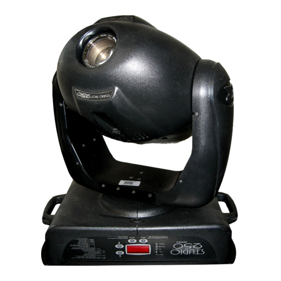
High End Systems Studio Spot 250 User Manual (180 pages)
Brand:
High End Systems
| Category:
Lighting Equipment
| Size: 4.13 MB
Table of Contents
Table of Contents
7
Symbols
17
Document Conventions
18
Physical Specifications
18
Specifications
18
Figure Intro-1. Studio Spot
19
Electrical Specifications
20
Environmental Specifications
20
LAD™ Safety Standards
20
Laser Aiming Device (LAD™) Specifications
20
Cable and Connector Specifications
21
Dichroic, Litho, and Effect Specifications
21
Lamp Specifications
21
Optional Accessories
22
Table Intro-1. Studio Spot
22
Figure 1-1. Removing the Bezel
23
Saving the Shipping Materials
23
Setup and Installation
23
Unpacking the Fixture
23
Setting the Fixture Voltage
24
Figure 1-2. Remove the Two Panel Covers
25
Figure 1-3. Loosen the Two Display Panel Retaining Screws
25
Figure 1-4. Lower the Display Panel
26
Figure 1-5. Circuit Board Containing the Three Switch Blocks
26
Figure 1-6. Voltage Select Label
26
Changing the Power Cord Cap
27
Installing a Line Cord Cap - U.K. Only
27
Vigtig Fikker Heds Information - Danmark
27
Homing the Fixture
28
Powering on the Fixture
28
Figure 1-7. Front Panel Display
29
Identifying Display Panel Components
29
Linking the Fixtures
29
Cable Connectors
30
Constructing Cabling
30
Figure 1-8. XLR 3-Pin Connector
30
Figure 1-9. XLR 5-Pin Connector
31
Setting up the Link
31
Figure 1-10. Data in and Data out Connectors on the Fixture's Side Panel
32
Figure 1-11. Linking the Fixtures
32
Constructing a Terminator
33
Figure 1-12. Data Cable Terminator
33
Mounting the Fixture
33
Figure 1-13. Rubber Feet on the Fixture
34
Mounting the Fixture on a Truss
34
Mounting the Fixture Upright
34
Truss or Other Support System
34
Clamp
35
Safety Cable
35
Figure 1-14. Attaching a Clamp and Safety Cable to the Fixture
36
Configuring the Fixture
37
Fixture Types
37
DMX Start Channel Control Method
38
Fixture Number Control Method
38
Selecting a Control Method
38
Assigning a Fixture Address
39
Channel Range
39
Determining the Unique DMX Start Channel
40
Table 2-1. Example: Determining the DMX Start Channel
40
Determining the Unique Fixture Number
41
Table 2-2. Example: Determining the Unique Fixture Number
41
Table 2-3. Example of Wasted DMX Channels
42
Wasted DMX Channels
42
Operating the Fixture
43
Programming Overview
43
Fixture Constructs
44
Programming with a DMX Controller
44
Table 3-1. Fixture Constructs and Channel Assignments
44
Pan and Tilt
45
Position
45
Color Function
46
Table 3-2. Color Function Settings
46
Cyan
47
Magenta
47
Table 3-3. Cyan Settings
47
Table 3-4. Magenta Settings
47
Beam Shaping
48
Table 3-5. Yellow Settings
48
Table 3-6. Beam Shaping Settings
48
Yellow
48
Color Position
49
Litho Function
50
Table 3-7. Color Position Settings
50
Table 3-8. Litho Function Settings
50
Litho Position
51
Litho Rotate
51
Table 3-9. Litho Rotate Settings
51
Effects
52
Effects Rotate
53
Focus
53
Iris
53
Table 3-10. Effects Rotate Settings
53
Table 3-11. Iris Settings
53
Shutter
54
Table 3-12. Shutter Settings
54
DIM
55
Macro/Lad
55
Mspeed (Motor Speed)
55
Control
56
Table 3-13. Macro/Lad™ Settings
56
Table 3-14. Control Settings
56
Updating Software
57
Uploading Software to the Fixture
57
Figure 4-1. Use the <Menu>, <Enter>, <Up>, and <Down> Keys to Navigate through the Menu System
59
Navigational Buttons
59
Understanding the Menu System
59
Accessing the Menu System
60
Menu Maps
60
Address Menu (ADDR)
78
Fixture Options
78
Set Menu (SET)
78
Setting Factory Defaults (FACT)
79
Figure 4-2. Perpendicularly-Hung Fixture
80
Inverting Tilt (T/IN)
80
Swapping Pan and Tilt (SWAP)
80
Changing the Display Output (DSPL)
81
Figure 4-4. Opposing Fixtures
81
Inverting Pan (P/IN)
81
Changing the Control Method (CHNL)
82
Inverting LED Characters (D/IN)
82
Mode Menu (MODE)
83
Setting the Fixture Type (TYPE)
83
Setting the Lamp Warning Message (LMPL)
83
Setting the User Type (USER)
84
Copying User Presets (PRST)
85
Copying User Settings (SETT)
85
Copying User Presets and Settings (ALL)
86
Crossloading Fixture Software (XLD)
86
Test Menu (TEST)
87
Homing the Fixture (HOME)
88
Turning the Lamp on or off (LAMP)
88
Copying the Boot Code (BOOT)
89
Performing Self Tests (SELF)
89
Placing the Fixture in Setup Mode (S/UP)
90
Information Menu (INFO)
91
Testing the LED Display (DISP)
91
Viewing the Current Logic Board Temperature (PCB)
91
Viewing the Current Fixture Head Temperature (HEAD)
92
Viewing the Current Fixture Hours (F/HR)
92
Viewing the Current Lamp Hours (L/HR)
92
Viewing DMX Status and Construct Values (FIXT)
93
Viewing the Current Software Version (VER)
93
Viewing the Number of Current Lamp Strikes (L/ST)
93
Viewing DMX Data for Another Device (DATA)
95
Resetting Fixture Hours (F/RS)
96
Viewing Sensor Information (SENS)
96
Preset Menu (PRST)
97
Resetting Lamp Hours (L/RS)
97
Setting Preset Playback (PLAY)
97
Editing an On-Board Memory Scene (EDIT)
98
Capturing a Preset Scene (CAPT)
99
Copying an On-Board Memory Scene (COPY)
99
Enabling the Preset Default (DFLT)
100
DMX Controller Vs. Stand Alone Operation
101
Preset Programming
101
Programming Overview
101
Scene
101
Macros
102
Mspeed Vs. Full Speed
102
Ramp Open, Snap Shut
102
Choosing a Scene to Create/Edit
103
Creating a Scene - Step by Step Example
103
Forward and Reverse Spins
103
Preset Programming
103
Choosing a Color Wheel Control Value (COLC)
104
Opening the Shutter (SHUT)
104
Selecting a DIM Value (DIM)
104
Selecting a Pan Value (PAN)
104
Selecting a Tilt Value (TILT)
104
Selecting a Color Wheel Position (COL)
105
Selecting a Cyan Wheel Position (CYAN)
105
Selecting a Magenta Wheel Position (MAGN)
105
Selecting a Yellow Wheel Position (YELW)
105
Choosing a Litho Wheel Control Value (LTOC)
106
Selecting a Litho Rotation (Within the Wheel) Value (LTR)
106
Selecting a Litho Wheel Position (LTO)
106
Selecting an Effects Wheel Position (FX)
106
Selecting a Beam Shaping (Lenticular) Wheel Position (BEAM)
107
Selecting an Effects Wheel Rotation Value (FXR)
107
Selecting the Focus Value (FCUS)
107
Selecting the Iris Value (IRIS)
107
Choosing a Macro (MACR)
108
Setting a Crossfade Value (XFAD)
108
Setting a Delay Value (DLAY)
108
Setting an Mspeed Value (MSPD)
108
Erasing the Scene (ZERO)
109
Setting the Time Unit (TIME)
109
Figure 5-1. Preset Playback Indicator
110
Playing Back a Loop
110
Synchronizing Preset Playback
110
Figure 5-2. Example of Synchronized Playback
111
Intended Audience
113
Laser Aiming Device (LAD™) Operation
113
Safety Precautions
113
Figure 6-1. LAD™ Labels on the Fixture
114
Overview of Operation
114
Aligning the Laser
115
Figure 6-2. Laser Aperture
115
Recommended Laser Use
115
Alignment Procedure
116
Figure 6-3. Ideal Position of the Laser
116
Figure 6-4. Orient the Fixture for Laser Alignment
116
Figure 6-5. Remove the Bezel
117
Figure 6-6. Locate the Center of the Beam on the Wall and Mark the Ideal Laser
118
Figure 6-7. LAD™ Mounting/Alignment Screws
119
General Maintenance
121
Replacing Fuses
121
Replacing Parts
121
Figure 7-1. Remove the Two Panel Covers
122
Table 7-1. Description and Function of Fuses
122
Figure 7-2. Loosen the Two Display Panel Retaining Screws
123
Figure 7-3. Lower the Display Panel
123
Figure 7-4. Fuses on the Circuit Board
123
Replacing the Lamp
124
Figure 7-5. Lamp Cap and Lamp Assembly Screws
125
Figure 7-6. Remove the Lamp Assembly
125
Figure 7-7. Remove the Lamp from the Lamp Socket
126
Figure 7-8. Remove the Fixture's Bezel
127
Replacing Dichroics
127
Figure 7-9. Cutout on the MID Plate under the Color Wheel
128
Figure 7-11. Determining the Coated Side of Dichroic Glass
129
Figure 7-12. Location of the Spring and Built-In Plastic Tab on the Wheel Housing
129
Replacing Lithos
129
Figure 7-13. Rotating Litho and Aperture Ring
130
Figure 7-14. Removing a Static Litho
130
Figure 7-15. Replacing a Static Litho
131
Figure 7-16. Replacing the Spring on a Rotating Litho or Effect
132
Replacing Effects
132
Figure 7-17. Remove the Fixture's Bezel
133
Figure 7-18. Location of the C-Clips, Lens Shafts, Focus Screw, and Lens Assembly
134
Figure 7-19. Location of the Eight Screws on the Optical Assembly Front Plate
134
Figure 7-20. Optical Assembly Cover Plate Folded Toward the Sensor Bracket
135
Replacing the Lens
136
Replacing the Studio Spot ® 250 Lens
136
Figure 7-21. the Three Lens Screws
137
Replacing the Studio Color ® 250 Lens
137
Figure 7-22. Remove the Screws that Secure the Lens to the Lens Assembly
138
Figure 7-23. Orient the Fixture for Lamp Optimization
139
Optimizing the Lamp
139
Cleaning the Glass Components
140
Figure 7-24. Lamp Optimization Screws
140
Chapter 8 Troubleshooting
141
LED Display Error Messages
141
Table 8-1. LED Error Messages
141
Status Leds
146
Table 8-2. Status Leds
146
General Troubleshooting
147
Table 8-3. General Troubleshooting
148
Upload and Crossload Troubleshooting
149
Table 8-4. Upload and Crossload Troubleshooting
150
Laser Aiming Device (LAD™) Troubleshooting
151
Table 8-5. LAD Troubleshooting
151
Appendix Admx Control
153
DMX Start Channels
153
Table A-1. DMX Start Channels
153
Construct Parameters
154
Table A-4. Mspeed Times
166
Appendix B Macros
169
Macro Descriptions
169
Table B-1. Macro Descriptions
169
Appendix C Important Safety Information
171
Appendice C
172
Importantes Informations Sur la Sécurité
172
Anhang C
173
Wichtige Hinweise für Ihre Sicherheit
173
Apéndice C
174
Información Importante de Seguridad
174
Appendice C
175
Importanti Informazioni DI Sicurezza
175
Vigtig Sikkerhedsinformation
176
Figure 2-1. Menu Navigation Buttons
178
Advertisement
Advertisement
Related Products
High End Systems SHOWGUN
High End Systems ShapeshifterW1
High End Systems Studio Color 250
High End Systems studio spot
High End Systems StudioPix Pixelation Luminaire
High End Systems studio color
High End Systems StudioPix
High End Systems SolaFrame 2000
High End Systems SolaHyBeam 2000
High End Systems SolaFrame Theatre
High End Systems Categories
Lighting Equipment
Light Fixture
DJ Equipment
Controller
Server
More High End Systems Manuals
Login
Sign In
OR
Sign in with Facebook
Sign in with Google
Upload manual
Upload from disk
Upload from URL