Sign In
Upload
Manuals
Brands
ABB Manuals
Controller
ACS800-04
ABB ACS800-04 Drive Module Manuals
Manuals and User Guides for ABB ACS800-04 Drive Module. We have
8
ABB ACS800-04 Drive Module manuals available for free PDF download: Cabinet Installation And Operating Instruction, Hardware Manual, Installation Manual, Application Manual
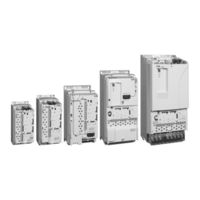
ABB ACS800-04 Hardware Manual (144 pages)
Drive Modules
Brand:
ABB
| Category:
Controller
| Size: 4.96 MB
Table of Contents
ACS800 Single Drive Manuals
10
Safety Instructions
13
What this Chapter Contains
13
Use of Warnings and Notes
13
Installation and Maintenance Work
14
Grounding
15
Mechanical Installation and Maintenance
16
Printed Circuit Boards
16
Fibre Optic Cables
16
Operation
17
Permanent Magnet Motor
18
Installation and Maintenance Work
18
Start-Up and Operation
18
Table of Contents
19
Table of Contents
25
About this Manual
25
What this Chapter Contains
25
Compatibility
25
Intended Audience
25
Categorization According to the Frame Size
25
Categorization According to the + Code
25
Contents
26
Installation and Commissioning Flowchart
27
Product and Service Inquiries
28
Product Training
28
Providing Feedback on ABB Drives Manuals
28
Terms and Abbreviations
29
Acs800-04/U4
31
What this Chapter Contains
31
Layout
31
Type Code
32
Main Circuit and Control
33
Diagram
33
Operation
34
Printed Circuit Boards
34
Motor Control
34
Planning the Cabinet Assembly
35
What this Chapter Contains
35
Cabinet Construction
35
Disposition of the Devices
35
Grounding of Mounting Structures
35
Free Space Around the Unit
36
Cooling and Degrees of Protection
37
Preventing the Recirculation of Hot Air
38
Outside the Cabinet
38
Inside the Cabinet
39
Cabinet Layout Example
39
Cabinet Heaters
40
Mounting the Optional Control Panel
40
Installing the Control Panel Directly on the Cabinet Door
40
Control Panel Mounting Platform Kit (RPMP)
41
EMC Requirements
41
Mechanical Installation
43
Unpacking the Unit
43
Delivery Check
44
Before Installation
44
Requirements for the Installation Site
44
Floor
44
Installation Procedure
45
Flange Mounting
46
Planning the Electrical Installation
49
What this Chapter Contains
49
Motor Selection and Compatibility
49
Protecting the Motor Insulation and Bearings
50
Requirements Table
51
Permanent Magnet Synchronous Motor
54
Supply Connection
54
Disconnecting Device (Means)
54
EEA / Europe
55
Main Contactor
55
Fuses
55
Thermal Overload and Short-Circuit Protection
55
Thermal Overload Protection of the Drive and the Input and Motor Cables
55
Thermal Overload Protection of the Motor
56
Protection against Short-Circuit in the Motor Cable
56
Protection against Short-Circuit Inside the Drive or in the Supply Cable
56
Ground Fault Protection
57
Emergency Stop Devices
57
Prevention of Unexpected Start
58
Selecting the Power Cables
59
General Rules
59
Alternative Power Cable Types
60
Motor Cable Shield
60
Additional US Requirements
61
Conduit
61
Armored Cable / Shielded Power Cable
61
Power Factor Compensation Capacitors
62
Equipment Connected to the Motor Cable
62
Installation of Safety Switches, Contactors, Connection Boxes, Etc
62
Bypass Connection
62
Before Opening a Contactor (DTC Control Mode Selected)
63
Protecting the Relay Output Contacts and Attenuating Disturbances in Case of Inductive Loads
63
Selecting the Control Cables
64
Relay Cable
64
Control Panel Cable
64
Connection of a Motor Temperature Sensor to the Drive I/O
65
Installation Sites above 2000 Metres (6562 Feet)
65
Routing the Cables
65
Control Cable Ducts
66
Electrical Installation
67
What this Chapter Contains
67
Checking the Insulation of the Assembly
67
Drive
67
Input Cable
67
Motor and Motor Cable
67
IT (Ungrounded) Systems
68
Power Cable Connection
69
Connecting the Power Cables
69
Grounding the Motor Cable Shield at the Motor End
70
Frame Sizes R2 to R4
71
Frame Size R5
71
Frame Size R6: Cable Lug Installation [16 to 70 Mm2 (6 to 2/0 AWG) Cables]
72
Power Cable Protection
73
Frame Size R5
73
Frame Size R6
74
Warning Sticker
74
Connecting the Control Cables
75
Terminals
75
Degrees Grounding
77
When the Outer Surface of the Shield Is Covered with Non-Conductive Material
77
Connecting the Shield Wires
77
Cabling of I/O and Fieldbus Modules
78
Pulse Encoder Module Cabling
78
Installation of Optional Modules and PC
79
Fibre Optic Link
79
External +24 V Power Supply for the RMIO Board Via Terminal X34
79
Parameter Settings
79
Connecting +24 V External Power Supply
79
Prevention of Unexpected Start, AGPS Board
82
Motor Control and I/O Board (RMIO)
85
What this Chapter Contains
85
Note on Terminal Labelling
85
Note on External Power Supply
85
Parameter Settings
85
External Control Connections (Non-US)
86
External Control Connections (US)
87
RMIO Board Specifications
88
Analogue Inputs
88
Constant Voltage Output
88
Auxiliary Power Output
88
Analogue Outputs
88
Digital Inputs
88
Relay Outputs
89
DDCS Fibre Optic Link
89
24 V DC Power Input
89
Installation Checklist
91
Checklist
91
Maintenance
93
What this Chapter Contains
93
Safety
93
Maintenance Intervals
93
Heatsink
93
Fan
94
Fan Replacement (R2, R3)
94
Fan Replacement (R4)
95
Fan Replacement (R5)
96
Fan Replacement (R6)
97
Additional Fan
97
Replacement (R2, R3)
97
Replacement (R4, R5)
98
Replacement (R6)
98
Capacitors
98
Reforming
98
Leds
98
Advertisement
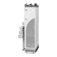
ABB ACS800-04 Hardware Manual (146 pages)
drive modules
Brand:
ABB
| Category:
Control Unit
| Size: 16.32 MB
Table of Contents
Table of Contents
5
Safety Instructions
11
What this Chapter Contains
11
Use of Warnings and Notes
11
Installation and Maintenance Work
12
Grounding
13
Mechanical Installation and Maintenance
14
Printed Circuit Boards
14
Fiber-Optic Cables
15
Operation
15
Permanent Magnet Motor
16
Installation and Maintenance Work
16
Start-Up and Operation
16
Introduction to this Manual
17
What this Chapter Contains
17
Target Audience
17
Categorization According to the Frame Size
17
Categorization According to the Plus Code
18
Contents
18
Installation, Commissioning and Operating Flowchart
19
Terms and Abbreviations
21
Operation Principle and Hardware Description
23
What this Chapter Contains
23
ACS800-04/U4 Product Overview
24
ACS800-04M Product Overview
25
Example Configurations
25
Type Designation Label
26
Type Code
27
Main Circuit and Control Interfaces
29
Diagram
29
Operation
29
Printed Circuit Boards
30
Motor Control
30
Connections of the RDCU Control Unit
31
Mechanical Installation
33
What this Chapter Contains
33
Unpacking the Unit
33
Before Installation
34
Delivery Check
34
Requirements for the Installation Site
34
Cooling Air Flow
35
Cable Channel in the Floor below the Cabinet
35
Attaching the Cabinet to the Floor and Wall
35
Electric Welding
35
Planning the Electrical Installation
37
What this Chapter Contains
37
Motor Selection and Compatibility
38
Protecting the Motor Insulation and Bearings
39
Requirements Table
40
Permanent Magnet Motor
44
Supply Connection
45
Disconnecting Device
45
Fuses
45
Main Contactor
45
Thermal Overload and Short-Circuit Protection
46
Thermal Overload Protection of the Drive and the Input and Motor Cables
46
Thermal Overload Protection of the Motor
46
Sensors
46
Protecting the Motor and Motor Cable in Short Circuits
47
Protection against Short Circuits in the Drive or Supply Cable
47
Ground Fault Protection
48
Emergency Stop Devices
48
Restarting after an Emergency Stop
48
Power-Loss Ride-Through Function
48
Prevention of Unexpected Start-Up (Option +Q950)
49
Terminal for the User Connection
50
Safe Torque off (Option +Q967)
51
Terminal for the User Connection
53
Selecting the Power Cables
54
Alternative Power Cable Types
55
Motor Cable Shield
55
Additional US Requirements
56
Conduit
56
Armored Cable / Shielded Power Cable
56
Power Factor Compensation Capacitors
57
Equipment Connected to the Motor Cable
57
Installation of Safety Switches, Contactors, Connection Boxes, Etc
57
Bypass Connection
57
Using a Contactor between the Drive and the Motor
58
Tive Loads
59
Selecting the Control Cables
60
Relay Cable
60
Control Panel Cable
60
Connection of a Motor Temperature Sensor to the Drive I/O
61
Installation Sites above 2000 Metres (6562 Feet)
61
Routing the Cables
62
Control Cable Ducts
62
Electrical Installation
63
What this Chapter Contains
63
Checking the Insulation of the Assembly
63
Drive
63
Supply Cable
63
Motor and Motor Cable
64
IT (Ungrounded) Systems
64
Installation of Optional EMC Filter (+E202)
64
Example Wiring Diagram
65
Power Cable Connection Diagram
66
Grounding of the Cable Shields
67
Fastening US Cable Lugs
68
Example Mounting
68
Connections of the RDCU
69
Connecting the Control Cables to the RMIO Board
70
Connecting the Shield Wires at the RMIO Board
70
Securing the Control Cables Mechanically
70
Settings of the Cooling Fan Transformer
71
Installation of Optional Modules
71
Cabling of I/O and Fieldbus Modules
71
Pulse Encoder Module Cabling
72
Fiber-Optic Link
72
Warning Sticker
72
Removing the Protective Covering from the Drive Module Air Outlet
73
Motor Control and I/O Board (RMIO)
75
What this Chapter Contains
75
Note on Terminal Labelling
75
Note on External Power Supply
76
Parameter Settings
76
External Control Connections (Non-US)
77
External Control Connections (US)
78
RMIO Board Specifications
79
Analogue Inputs
79
Constant Voltage Output
79
Auxiliary Power Output
79
Analogue Outputs
79
Digital Inputs
79
Relay Outputs
80
DDCS Fiber-Optic Link
80
DC Power Input
80
Installation Checklist
83
What this Chapter Contains
83
Checklist
83
Start-Up and Use
85
What this Chapter Contains
85
Start-Up Procedure
86
Control Panel
87
Removing the Control Panel
87
Maintenance
89
What this Chapter Contains
89
Safety
89
Maintenance Intervals
90
Layout
91
Heatsink
92
Fan
92
Replacing the Fan (R7)
93
Replacing the Fan (R8)
94
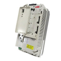
ABB ACS800-04 Cabinet Installation And Operating Instruction (162 pages)
Drive Modules
Brand:
ABB
| Category:
Industrial Electrical
| Size: 17.02 MB
Table of Contents
ACS800 Single Drive Manuals
2
Table of Contents
5
Table of Contents
11
About this Manual
11
What this Chapter Contains
11
Target Audience
11
Safety
11
Other Related Manuals
11
Categorization According to the Frame Size
12
Categorization According to the Plus Code
12
Contents
12
Installation, Commissioning and Operating Flowchart
13
Product and Service Inquiries
14
Product Training
14
Providing Feedback on ABB Drives Manuals
14
The ACS800-04/U4 and ACS800-04M
15
What this Chapter Contains
15
The ACS800-04/U4
15
The ACS800-04M
16
Example Configurations
16
Type Designation Label
17
Type Code
18
Main Circuit and Control Interfaces
20
Connections of the Drive Control Unit (RDCU) in Frame Sizes R7 and R8
21
Operation
21
Printed Circuit Boards
22
Motor Control
22
Planning the Cabinet Installation
23
What this Chapter Contains
23
Cabinet Construction
23
Disposition of the Devices
23
Layout Examples, Door Closed
24
Layout Examples, Door Open
25
Grounding of Mounting Structures
26
Busbar Material and Joints
26
Tightening Torques
26
Cabinet Cooling
26
Cabinet Cooling Data
28
IP 22 Cabinet with no Extra Fan
28
IP 54 Cabinet with an Extra Fan
28
Preventing the Recirculation of Hot Air
29
Outside the Cabinet
29
Inside the Cabinet
29
Cubicle Heaters
29
Required Free Space Around the Drive Module for Cooling
30
Free Space at the Top of the Drive Module
30
Free Space Around Units with Busbars on the Long Side (Bookshelf Mounting +H354)
31
Free Space Around Units with Busbars on the Short Side (Flat Mounting +H360)
32
When the Drive Module Is Installed in Another Position than Vertically
33
Drive Module of Frame Size R7 on Its Side
33
Drive Module of Frame Size R7 on Its Back
34
EMC Requirements
35
Grounding of Cable Shields
36
Installing the Drive Control Unit (RDCU)
36
Fastening of the Control Panel (CDP312R)
37
Installing the Control Panel Directly on the Cabinet Door
37
Control Panel Mounting Platform RPMP-11/13 (+J410)
37
Control Panel Holder RPMP-21 (+J413)
38
Mechanical Installation of Pre-Assembled Units (ACS800-04/U4)
39
What this Chapter Contains
39
Moving and Unpacking the Unit
39
Delivery Check
40
Required Tools
41
Installation Procedure
42
Fasten the Module to the Cabinet
42
Clamping the Pedestal with the Outside Brackets
42
Fasten the Terminals to the Busbars
42
View of Output Busbar Connections of Frame Size R7 (DC and Brake Busbars Included)
43
View of Output Busbar Connections of Frame Size R8 (DC and Brake Busbars Included)
44
User Connections of Prevention of Unexpected Start (+Q950)
44
Mechanical Installation of Non-Pre-Assembled Units (ACS800-04M)
45
What this Chapter Contains
45
How to Read this Chapter
45
Units with Bottom Exit
45
Units with Pedestal and Busbars on the Long Side (+H354, Bookshelf Mounting)
45
Units with Pedestal and Busbars on the Short Side (+H360, Flat Mounting)
45
Required Tools and Tightening Torques
46
Moving and Unpacking the Unit
46
Frame Size R7 Units with Bottom Exit (+H352)
49
Delivery Check
49
Assembling Procedure
53
Fastening the Spacer
55
Fastening the Top Entry Busbar and Bottom Exit Shrouds (+B060)
55
Top Entry Busbar Shroud
55
Bottom Exit Shroud
56
Units with Pedestal and Busbars on the Long Side (+H354, Bookshelf Mounting)
57
Delivery Check
57
Item Packages
57
Item Packages of Frame Size R7 with Busbars on the Long Side
58
Item Packages of Frame Size R8 with Busbars on the Long Side
64
Assembling Procedure for Units with Busbars on the Long Side (+H354)
73
Working Order
73
Connecting the DC Busbars to the Pedestal (+H356 and +H363 Only)
76
Procedure
76
Photos of Frame Size R7
76
Photos of Frame Size R8
77
Busbars to the Left- or Right-Hand Side of the Module
78
Swapping the Busbars of the Pedestal to the Other Side
78
Optional Selection +H363
79
Fastening the Pedestal to the Cabinet Base (Not for Wall-Mounted Units)
80
Clamping the Pedestal with the Outside Brackets
80
Fastening the Pedestal through the Holes Inside the Pedestal
80
Fastening the Drive Module by Top to the Cabinet Frame
81
Fastening the Drive Module to Wall (Wall-Mounted Units Only, Not for Base-Mounted Units)
81
Requirements for Protection
81
Requirements for the Wall
81
Floor
81
Procedure
82
Fastening the Output Busbars and PE Terminal and Sliding the Module in
86
View of Output Busbar Connections of Frame Size R7 (DC and Brake Busbars Included)
87
View of Output Busbar Connections of Frame Size R8 (DC and Brake Busbars Included)
88
Fastening the Drive Module to the Pedestal
89
Fastening the Shrouds in Frame Size R8
90
Top Entry Busbar Shroud
90
Vertical Busbar Shroud
90
Units with Pedestal and Busbars on the Short Side (+H360, Flat Mounting)
91
Delivery Check
91
Item Packages
91
Item Packages of Frame Size R7 with Busbars on the Short Side
92
Item Packages of Frame Size R8 with Busbars on the Short Side
98
Assembling Procedure for Units with Busbars on the Short Side (+H360)
104
Working Order
104
Swapping the Pedestal Output Busbars to the Left-Hand Side
106
Connecting the DC Busbars to the Pedestal (+H360 +H356 Only)
107
Required Parts
107
Procedure
107
Preparing the Adapter (+H360 +H356 Only)
108
Required Parts
108
Procedure
108
Fastening the Adapter to the Drive Module
109
Fastening the Drive Module to the Pedestal Via the Adapter
110
Connecting the Output Busbars on the Short Side of the Module
111
Procedure for Frame Size R7
111
Procedure Frame Size R8
113
Advertisement
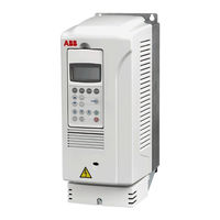
ABB ACS800-04 Hardware Manual (118 pages)
ACS800 series
Brand:
ABB
| Category:
Controller
| Size: 2.84 MB
Table of Contents
ACS800 Single Drive Manuals
2
Safety Instructions
5
What this Chapter Contains
5
To Which Products this Chapter Applies
5
Use of Warnings and Notes
5
Installation and Maintenance Work
6
Grounding
7
Mechanical Installation and Maintenance
8
Printed Circuit Boards
9
Fibre Optic Cables
9
Operation
10
Permanent Magnet Motor
11
Installation and Maintenance Work
11
Start-Up and Operation
11
Table of Contents
13
Table of Contents
19
About this Manual
19
What this Chapter Contains
19
Target Audience
19
Common Chapters for Several Products
19
Categorization According to the Frame Size
19
Categorization According to the Plus Code
19
Contents
20
Other Related Manuals
20
Installation, Commissioning and Operating Flowchart
20
Product and Service Inquiries
21
Product Training
21
Providing Feedback on ABB Drives Manuals
22
The ACS800-04/U4 and ACS800-04M
23
What this Chapter Contains
23
The ACS800-04/U4
23
The ACS800-04M
24
Example Configurations
24
Type Designation Label
25
Type Code
26
Control Interfaces
28
Connections of the Drive Control Unit (RDCU) in Frame Sizes R7 and R8
29
Operation
29
Printed Circuit Boards
30
Motor Control
30
Mechanical Installation
31
What this Chapter Contains
31
Before Installation
31
Delivery Check
31
Requirements for the Installation Site
31
Cooling Air Flow
31
Cable Channel in the Floor below the Cabinet
32
Fastening the Cabinet to the Floor and Wall
32
Electric Welding
32
Planning the Electrical Installation
33
What this Chapter Contains
33
To Which Products this Chapter Applies
33
Motor Selection and Compatibility
33
Protecting the Motor Insulation and Bearings
35
Requirements Table
36
Permanent Magnet Synchronous Motor
39
Supply Connection
40
Disconnecting Device (Disconnecting Means)
40
ACS800-01, ACS800-U1, ACS800-11, ACS800-U11, ACS800-31, ACS800-U31, ACS800-02 and ACS800-U2 Without Enclosure Extension, ACS800-04, ACS800-U4
40
ACS800-02 and ACS800-U2 with Enclosure Extension, ACS800-07 and ACS800-U7
40
Fuses
40
Main Contactor
40
Thermal Overload and Short-Circuit Protection
41
Thermal Overload Protection of the Drive and the Input and Motor Cables
41
Thermal Overload Protection of the Motor
41
Protection against Short-Circuit in the Motor Cable
41
Protection against Short-Circuit Inside the Drive or in the Supply Cable
42
Ground Fault Protection
43
Emergency Stop Devices
43
ACS800-02/U2 with Enclosure Extension and ACS800-07/U7
43
Restarting after an Emergency Stop
43
Power-Loss Ride-Through Function
44
ACS800-07/U7 Units Without Line Contactor
44
ACS800-07/U7 Units with Line Contactor (+F250)
44
Prevention of Unexpected Start
45
Selecting the Power Cables
46
General Rules
46
Alternative Power Cable Types
47
Motor Cable Shield
47
Additional US Requirements
48
Conduit
48
Armored Cable / Shielded Power Cable
48
Power Factor Compensation Capacitors
48
Equipment Connected to the Motor Cable
49
Installation of Safety Switches, Contactors, Connection Boxes, Etc
49
Bypass Connection
49
Before Opening a Contactor (DTC Control Mode Selected)
49
Protecting the Relay Output Contacts and Attenuating Disturbances in Case of Inductive Loads
50
Selecting the Control Cables
51
Relay Cable
51
Control Panel Cable
51
Connection of a Motor Temperature Sensor to the Drive I/O
52
Installation Sites above 2000 Metres (6562 Feet)
52
Routing the Cables
52
Control Cable Ducts
53
Electrical Installation
55
What this Chapter Contains
55
Warnings
55
Checking the Insulation of the Assembly
55
Drive
55
Input Cable
55
Motor and Motor Cable
55
IT (Ungrounded) Systems
56
Installation of Optional EMC Filter (+E202)
56
Example Wiring Diagram
57
Power Cable Connection Diagram
58
Grounding of the Cable Shields
59
Fastening US Cable Lugs
60
Example Mounting
60
Connections of the RDCU
61
Connecting the Control Cables to the RMIO Board
62
Connecting the Shield Wires at RMIO Board
62
Securing the Control Cables Mechanically
62
Settings of the Cooling Fan Transformer
63
Installation of Optional Modules
63
Cabling of I/O and Fieldbus Modules
63
Pulse Encoder Module Cabling
64
Fibre Optic Link
64
Warning Sticker
64
Motor Control and I/O Board (RMIO)
65
What this Chapter Contains
65
To Which Products this Chapter Applies
65
Note for the ACS800-02 with Enclosure Extension and the ACS800-07
65
Note on Terminal Labelling
65
Note on External Power Supply
66
Parameter Settings
66
External Control Connections (Non-US)
67
External Control Connections (US)
68
RMIO Board Specifications
69
Analogue Inputs
69
Constant Voltage Output
69
Auxiliary Power Output
69
Analogue Outputs
69
Digital Inputs
69
Relay Outputs
70
DDCS Fibre Optic Link
70
24 VDC Power Input
70
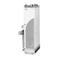
ABB ACS800-04 Hardware Manual (114 pages)
Drive Modules (90 to 500 kW) Drive Modules (125 to 600 HP)
Brand:
ABB
| Category:
Control Unit
| Size: 3.32 MB
Table of Contents
ACS 800 Single Drive Manuals
2
Table of Contents
5
Table of Contents
10
Safety Instructions
11
What this Chapter Contains
11
To Which Products this Chapter Applies
11
Use of Warnings and Notes
11
Installation and Maintenance Work
12
Grounding
13
Fibre Optic Cables
13
Mechanical Installation
14
Operation
14
Permanent Magnet Motor
15
Installation and Maintenance Work
15
Operation
15
About this Manual
17
What this Chapter Contains
17
Target Audience
17
Common Chapters for Three Products
17
Categorization According to the Frame Size
17
Contents
17
Installation and Commissioning Flowchart
18
Inquiries
19
The ACS800-04/U4
21
What this Chapter Contains
21
Control Interfaces
22
Type Code
23
Main Circuit and Control
24
Diagram
24
Operation
24
Printed Circuit Boards
25
Motor Control
25
Cabinet Construction
27
Disposition of the Devices
27
Grounding of Mounting Structures
27
Busbar Material and Joints
27
Tightening Torques
28
Cabinet Assembly Planning
27
What this Chapter Contains
27
Cooling and Degrees of Protection
28
Preventing the Recirculation of Hot Air
30
Outside the Cabinet
30
Inside the Cabinet
30
Cubicle Heaters
30
Fastening of the Control Panel (CDP312R)
31
Installing the Control Panel Directly on the Cabinet Door
31
Control Panel Mounting Platform Kit (RPMP)
31
Cabinet Layout Examples
33
What this Chapter Contains
33
Layout, Door Closed
34
Layout, Door Open
35
Electrical Installation Planning
37
What this Chapter Contains
37
To Which Products this Chapter Applies
37
Checking the Compatibility of the Motor
37
Protecting the Motor Winding and Bearings
37
Requirements Table
38
Permanent Magnet Synchronous Motor
40
Supply Connection
40
Disconnecting Device (Means)
40
Fuses
41
Thermal Overload and Short-Circuit Protection
41
Mains Cable (AC Line Cable) Short-Circuit Protection
41
Ground Fault Protection
41
Emergency Stop Devices
42
Selecting the Power Cables
42
General Rules
42
Alternative Power Cable Types
43
Motor Cable Shield
43
Additional US Requirements
44
Conduit
44
Armored Cable / Shielded Power Cable
44
Power Factor Compensation Capacitors
44
Equipment Connected to the Motor Cable
45
Installation of Safety Switches, Contactors, Connection Boxes, Etc
45
Bypass Connection
45
Before Opening a Contactor (DTC Control Mode Selected)
45
Protecting the Relay Output Contacts and Attenuating Disturbances in Case of Inductive Loads
46
Selecting the Control Cables
47
Relay Cable
47
Control Panel Cable
47
Connection of a Motor Temperature Sensor to the Drive I/O
48
Routing the Cables
48
Installation
49
Installation
51
What this Chapter Contains
51
Moving and Unpacking the Unit
51
Before Installation
53
Delivery Check
53
Requirements for the Installation Site
54
Cooling Air Flow
54
IT (Ungrounded) Systems
54
Required Tools
54
Checking the Insulation of the Assembly
55
Example Wiring Diagram
56
Power Cable Connection Diagram
57
Installation Procedure
58
Fastening the Module to the Cabinet
58
Fastening the Module with the Outside Brackets
58
Fastening the Module through the Holes Inside the Pedestal
58
Fastening the Terminals to the Busbars
61
Fastening and Connecting the RDCU
62
Connecting the Control Cables to the RMIO Board
63
Connecting the Shield Wires at RMIO Board
63
Securing the Control Cables Mechanically
63
Settings of the Cooling Fan Transformer
64
Installation of Optional Modules
64
Cabling of I/O and Fieldbus Modules
64
Pulse Encoder Module Cabling
65
Fibre Optic Link
65
Warning Sticker
65
Installation of Brake Resistors (Units with Brake Chopper Option)
65
Parameter Settings
65
Motor Control and I/O Board (RMIO)
67
What this Chapter Contains
67
To Which Products this Chapter Applies
67
Note for the ACS800-02
67
Note for External Power Supply
67
External Control Connections (Non-US)
68
External Control Connections (US)
69
RMIO Board Specifications
70
Analogue Inputs
70
Constant Voltage Output
70
Auxiliary Power Output
70
Analogue Outputs
70
Digital Inputs
70
Relay Outputs
71
DDCS Fibre Optic Link
71
24 VDC Power Input
71
Checking the Installation
73
ABB ACS800-04 Hardware Manual (104 pages)
Brand:
ABB
| Category:
DC Drives
| Size: 2.73 MB
Table of Contents
ACS800 Single Drive Manuals
2
Safety Instructions
5
What this Chapter Contains
5
To Which Products this Chapter Applies
5
Use of Warnings and Notes
5
Installation and Maintenance Work
6
Grounding
7
Mechanical Installation and Maintenance
8
Printed Circuit Boards
9
Fibre Optic Cables
9
Operation
10
Permanent Magnet Motor
11
Installation and Maintenance Work
11
Start-Up and Operation
11
Table of Contents
13
About this Manual
19
What this Chapter Contains
19
Target Audience
19
Common Chapters for Several Products
19
Categorization According to the Frame Size
19
Categorization According to the Plus Code
19
Contents
20
Other Related Manuals
20
Installation, Commissioning and Operating Flowchart
20
Inquiries
21
The ACS800-04/U4 and ACS800-04M
23
What this Chapter Contains
23
The ACS800-04/U4
23
The ACS800-04M
24
Example Configurations
24
Type Designation Label
25
Type Code
26
Control Interfaces
28
Connections of the Drive Control Unit (RDCU) in Frame Sizes R7 and R8
29
Operation
29
Printed Circuit Boards
30
Motor Control
30
Mechanical Installation
31
What this Chapter Contains
31
Before Installation
31
Delivery Check
31
Requirements for the Installation Site
31
Cooling Air Flow
31
Cable Channel in the Floor below the Cabinet
32
Fastening the Cabinet to the Floor and Wall
32
Electric Welding
32
Planning the Electrical Installation
33
What this Chapter Contains
33
To Which Products this Chapter Applies
33
Motor Selection and Compatibility
33
Protecting the Motor Insulation and Bearings
34
Requirements Table
35
Permanent Magnet Synchronous Motor
37
Supply Connection
37
Disconnecting Device (Disconnecting Means)
37
ACS800-01, ACS800-U1, ACS800-11, ACS800-U11, ACS800-02, ACS800-U2 Without Enclosure Extension, ACS800-04, ACS800-U4
37
ACS800-U2 with Enclosure Extension, ACS800-07 and ACS800-U7
37
Fuses
37
Thermal Overload and Short-Circuit Protection
38
Mains Cable (AC Line Cable) Short-Circuit Protection
38
Acs800-04/U4
38
Drive AC Fuses (ACS800-07/U7, and ACS800-02/U2 with Enclosure Extension)
38
Operating Time of the Fuses
38
Circuit Breakers
39
Ground Fault Protection
39
Emergency Stop Devices
39
ACS800-02/U2 with Enclosure Extension and ACS800-07/U7
39
Restarting after an Emergency Stop
39
Prevention of Unexpected Start
40
Selecting the Power Cables
41
General Rules
41
Alternative Power Cable Types
42
Motor Cable Shield
42
Additional US Requirements
43
Conduit
43
Armored Cable / Shielded Power Cable
43
Power Factor Compensation Capacitors
43
Equipment Connected to the Motor Cable
44
Installation of Safety Switches, Contactors, Connection Boxes, Etc
44
Bypass Connection
44
Before Opening a Contactor (DTC Control Mode Selected)
44
Protecting the Relay Output Contacts and Attenuating Disturbances in Case of Inductive Loads
45
Selecting the Control Cables
46
Relay Cable
46
Control Panel Cable
46
Connection of a Motor Temperature Sensor to the Drive I/O
47
Routing the Cables
47
Control Cable Ducts
48
Electrical Installation
49
What this Chapter Contains
49
Warnings
49
Checking the Insulation of the Assembly
49
IT (Ungrounded) Systems
50
Example Wiring Diagram
51
Power Cable Connection Diagram
52
Grounding of the Cable Shields
53
Fastening US Cable Lugs
54
Example Mounting
54
Connections of the RDCU
55
Connecting the Control Cables to the RMIO Board
56
Connecting the Shield Wires at RMIO Board
56
Securing the Control Cables Mechanically
56
Settings of the Cooling Fan Transformer
57
Installation of Optional Modules
57
Cabling of I/O and Fieldbus Modules
57
Pulse Encoder Module Cabling
58
Fibre Optic Link
58
Warning Sticker
58
Motor Control and I/O Board (RMIO)
59
What this Chapter Contains
59
To Which Products this Chapter Applies
59
Note for the ACS800-02 with Enclosure Extension and the ACS800-07
59
Note on External Power Supply
59
External Control Connections (Non-US)
60
External Control Connections (US)
61
RMIO Board Specifications
62
Analogue Inputs
62
Constant Voltage Output
62
Auxiliary Power Output
62
Analogue Outputs
62
Digital Inputs
62
Relay Outputs
63
DDCS Fibre Optic Link
63
24 VDC Power Input
63
Maintenance
65
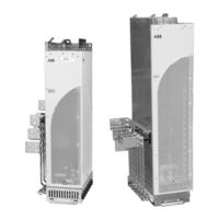
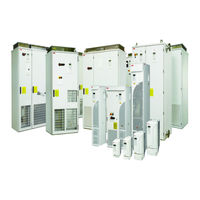
ABB ACS800-04 Application Manual (46 pages)
INDUSTRIAL DRIVES, Safe torque off function (+Q967)
Brand:
ABB
| Category:
DC Drives
| Size: 7.57 MB
Table of Contents
Table of Contents
5
1 Introduction to the Manual
7
Contents of this Chapter
7
Applicability
7
Safety Instructions
7
Target Audience
8
Contents
8
Abbreviations
9
2 Option Description
11
Contents of this Chapter
11
Description
11
Operation Principle
12
STO Status Indications
13
STO Function Activation and Indication Response Times
14
Module Response Times Only
14
Response Times with Typical Safety Relay
14
3 Installation
15
Contents of this Chapter
15
Supply Voltage
15
Connections
15
STO Input
15
Activation Switch
16
Cable Types and Lengths
16
Cable between STO Activation Switch and Drive/Inverter Module or ASTO Board
16
Cable between ASTO Board and Drive/Inverter Module
16
Example Wiring Diagrams
17
STO Connections Without Safety Relays
17
Connecting the STO Activation Switch
17
Frame Sizes R2 to R6
18
Frame Sizes R7 and R8
18
Frame Sizes R2I to R4I
19
Frame Size R5I
19
Frame Size R7I
20
Frame Size R8I
20
Liquid-Cooled Modules of Frame Sizes R7I and R8I
21
STO Connections with Safety Relays
22
Frame Sizes R2 to R6
22
Frame Sizes R7 and R8
23
Frame Sizes R2I to R4I
24
Frame Size R5I
25
Frame Size R7I
26
Frame Size R8I
27
Connecting Several Drive/Inverter Modules or Inverter Units to One Safety Relay
28
4 Start-Up and Use
29
Contents of this Chapter
29
Start-Up and Acceptance Test
29
Competence
29
Acceptance Test Reports
30
Acceptance Test Procedure
30
Use
31
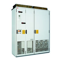
ABB ACS800-04 Installation Manual (52 pages)
Rittal TS 8 Cabinet Installation
Brand:
ABB
| Category:
Industrial Electrical
| Size: 4.46 MB
Table of Contents
ACS800 Single Drive Manuals
2
Table of Contents
5
About this Manual
7
What this Chapter Contains
7
Target Audience
7
Safety
7
What this Manual Contains
7
Other Related Manuals
8
Component Lists
8
Categorization According to the Frame Size
9
Take Care of Sufficient Cooling
9
Liability
9
Drive Module of Frame Size R7 with Bottom Exit
11
What this Chapter Contains
11
Rittal Parts
11
ACS800-04M Parts
11
Additional Parts to be Provided by the Installer
12
Moving, Unpacking and Assembling the Drive Module
12
Layout of the Installation
13
Installation Steps
14
Cable Lead-Through Plates
20
Fastening of the Back Mounting Plate
21
Fastening of the RDCU Drive Control Unit to the Side Mounting Plate
22
What this Chapter Contains
23
Required Rittal Parts
23
ACS800-04M Parts
23
Additional Parts to be Provided by the Installer
23
Moving, Unpacking and Assembling the Drive Module
24
View of the Installation
24
Layout of the Installation
25
Cooling Air Flow
26
Installation Steps
27
Drive Module of Frame Size R8 and Rittal Cooling Unit
29
Layout Example with Cooling Unit on the Side
29
Layout Example with Cooling Unit on the Door
30
Drive Module of Frame Size R8
31
What this Chapter Contains
31
Required Rittal Parts
31
ACS800-04M Parts
32
Additional Parts to be Provided by the Installer
32
Moving, Unpacking and Assembling the Drive Module
32
Layout of the Installation
33
Installation Steps
34
View of Base Plates and Cable Lead-Throughs Fastened
40
Fastening of the Punched Sections
41
Fastening the Drive Pedestal to the Enclosure Frame
41
Fastening of the Back Mounting Plate
41
Dimensional Drawings
43
What this Chapter Contains
43
Frame Size R7
44
Advertisement
Related Products
ABB ACS800-04M
ABB ACS800-01
ABB ACS800-37-0170-3
ABB ACS800-37-0460-5
ABB ACS800-37-1330-7
ABB ACS800-37-1510-7
ABB ACS800-U11-0016-2
ABB ACS800-U11-0030-5
ABB ACS800-U11-0020-5
ABB ACS800-11-0100-5
ABB Categories
Industrial Equipment
Controller
Measuring Instruments
Battery Charger
DC Drives
More ABB Manuals
Login
Sign In
OR
Sign in with Facebook
Sign in with Google
Upload manual
Upload from disk
Upload from URL