ABB ACS800-U4 Hardware Manual
Drive modules (90 to 500 kw)
drive modules (125 to 600 hp)
Hide thumbs
Also See for ACS800-U4:
- Hardware manual (144 pages) ,
- Firmware manual (214 pages) ,
- Cabinet installation and operating instruction (162 pages)
Table of Contents
Advertisement
Quick Links
Download this manual
See also:
Hardware Manual
Advertisement
Table of Contents

Related Manuals for ABB ACS800-U4


Summary of Contents for ABB ACS800-U4
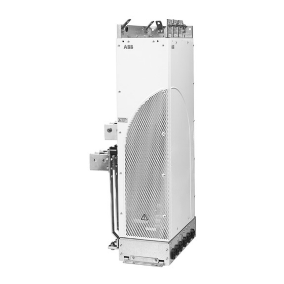
- Page 1 ACS 800 Hardware Manual ACS800-04 Drive Modules (90 to 500 kW) ACS800-U4 Drive Modules (125 to 600 HP)
-
Page 2: Acs 800 Single Drive Manuals
ACS 800 Single Drive Manuals GENERAL MANUALS ACS800-01/U1 Hardware Manual 1.1 to 110 kW (1.5 to 150 HP) 3AFE 64382101 (English) • Safety instructions • Electrical installation planning • Mechanical and electrical installation • Motor control and I/O board (RMIO) •... - Page 3 ACS800-04 Drive Modules 90 to 500 kW ACS800-U4 Drive Modules 125 to 600 HP Hardware Manual 3AFE 64671006 Rev A EN EFFECTIVE: 29.10.2002 SUPERSEDES: none ã 2002 ABB Oy. All Rights Reserved.
-
Page 5: Table Of Contents
Table of contents ACS 800 Single Drive Manuals ........... . 2 Table of contents Safety instructions What this chapter contains . - Page 6 Cabinet construction ............27 Disposition of the devices .
- Page 7 Selecting the control cables ............47 Relay cable .
- Page 8 RMIO board specifications ............70 Analogue inputs .
- Page 9 Cabinet assembly data ............89 IP 22 cabinet with no extra fan .
-
Page 10: Table Of Contents
Table of contents... -
Page 11: Safety Instructions
Safety instructions What this chapter contains This chapter contains the safety instructions which you must follow when installing, operating and servicing the drive. If ignored, physical injury or death may follow, or damage may occur to the drive, the motor or driven equipment. Read the safety instructions before you work on the unit. -
Page 12: Installation And Maintenance Work
Installation and maintenance work These warnings are intended for all who work on the drive, motor cable or motor. Ignoring the instructions can cause physical injury or death. Only qualified electricians are allowed to install and maintain the drive. • Never work on the drive, the motor cable or the motor when main power is applied. -
Page 13: Grounding
Grounding These instructions are intended for all who are responsible for the grounding of the drive. Incorrect grounding can cause physical injury, death or equipment malfunction and increase electromagnetic interference. • Ground the drive, the motor and adjoining equipment to ensure personnel safety in all circumstances, and to reduce electromagnetic emission and pick- •... -
Page 14: Mechanical Installation
Mechanical installation These notes are intended for all who install the drive. Handle the unit carefully to avoid damage and injury. • ACS800-01: The drive is heavy. Do not lift it alone. Do not lift the unit by the front cover. Place the unit only on its back. ACS800-02, ACS800-04: The drive is heavy. -
Page 15: Permanent Magnet Motor
Permanent magnet motor These are additional warnings concerning permanent magnet motor drives. WARNING! Do not work on the drive when the permanent magnet motor is rotating. Also when the supply power is switched off, a rotating permanent magnet motor feeds power to the intermediate circuit of the drive and also the supply connections become live (even when the inverter is stopped!). - Page 16 Safety instructions...
-
Page 17: About This Manual
About this manual What this chapter contains This chapter describes the intended audience and contents of the manual. It contains a flowchart of steps in checking the delivery, installing and commissioning the drive. The flowchart refers to chapters/sections in this manual and other manuals. -
Page 18: Installation And Commissioning Flowchart
If the converter has been non-operational for equipment are present and correct. more than one year, the converter DC link capacitors need to be reformed. Ask ABB for Only intact units may be started up. instructions. Check the installation site. -
Page 19: Inquiries
Inquiries Address any inquiries about the product to the local ABB representative, quoting the type code and the serial number of the unit. If the local ABB representative cannot be contacted, address inquiries to the manufacturing facility. About this manual... - Page 20 About this manual...
-
Page 21: The Acs800-04/U4
The ACS800-04/U4 What this chapter contains This chapter describes the construction and operating principle of the drive in short. The ACS800-04/U4 The ACS800-04/U4 is an IP 00 drive module for controlling AC motors. It is to be installed into a cabinet by the customer. The input cable terminals are located at the top of the unit whereas the motor cable terminals are located at the left hand side of the unit. -
Page 22: Control Interfaces
Control interfaces The control interfaces of the ACS800-04/U4 are shown below. Cables coming from the drive module Outside the module: (79 in.) AINT 3.5 m (138 in.) Frame Power supply cable length size Total Outside the module 2800 mm (110 in.) 2000 mm (79 in.) 3710 mm (146 in.) 2410 mm (95 in.) APOW Motor control... -
Page 23: Type Code
Type code The type code contains information on the specifications and configuration of the drive. The first digits from left express the basic configuration (e.g. ACS800-04- 0170-5). The optional selections are given thereafter, separated by + signs (e.g. +E202). The main selections are described below. Not all selections are available for all types. -
Page 24: Main Circuit And Control
Main circuit and control Diagram This diagram shows the control interfaces and the main circuit of the drive. Motor Optional module 1: RMBA, RAIO, control and RDIO, RDNA, RLON, RIBA, RPBA, I/O board RCAN, RCNA, RMBP, RETA or RTAC (RMIO) Optional module 2: RTAC, RAIO or External control via RDIO... -
Page 25: Printed Circuit Boards
Printed circuit boards The drive contains the following printed circuit boards as standard: • main circuit board (AINT) • motor control and I/O board (RMIO-02) with a fibre optic link to the AINT board • input bridge control board (AINP) •... - Page 26 The ACS800-04/U4...
-
Page 27: Cabinet Assembly Planning
Cabinet assembly planning What this chapter contains This chapter guides in planning the installation of a converter module into a user- defined cabinet. The issues discussed are essential for the safe and trouble-free use of the drive system. Cabinet construction The cabinet frame must be sturdy enough to carry the weight of the drive components, control circuitry and other equipment installed in it. -
Page 28: Tightening Torques
Tightening torques The following table applies to zinc and chrome platings, and grade 8.8 screws (with or without joint compound). Screw size Torque Soft aluminium Alloyed aluminium and copper lbf ft lbf ft 12.5 14.8 25.8 29.5 40.6 51.6 95.9 132.8 Cooling and degrees of protection The cabinet must have enough free space for the components to ensure sufficient... - Page 29 Arrange the cooling air flow through the converter module so that the requirements given in chapter Technical data are met: • cooling air flow Note: The figures in Technical data apply to continuous nominal load. If the load is cyclic or less than nominal, less cooling air is required.
-
Page 30: Preventing The Recirculation Of Hot Air
Preventing the recirculation of hot air Converter cubicle from side Converter cubicle from above A - A Vertical air baffle Air flow out Converter module Horizontal air baffle Converter module Air flow in Outside the cabinet Prevent hot air circulation outside the cabinet by leading the outcoming hot air away from the area where the inlet air to the cabinet is taken. -
Page 31: Fastening Of The Control Panel (Cdp312R)
Fastening of the control panel (CDP312R) The control panel can be fastened directly to the cabinet door or to a mounting platform. Installing the control panel directly on the cabinet door Fasten the control panel from the back side with two screws of one of the following types: •... - Page 32 Cabinet assembly planning...
-
Page 33: Cabinet Layout Examples
Cabinet layout examples What this chapter contains This chapter contains cabinet layout examples for the ACS800-04/U4 modules. Cabinet layout examples... -
Page 34: Layout, Door Closed
Layout, door closed IP 22 IP 54 1a Air inlet for the converter module 1b Air inlet for the other equipment 2a Air outlet for the converter module 2b Air outlet for the other equipment 2c Air outlet for the converter module and the other equipment, an extra exhaust fan Converter control panel (connected to the RMIO board inside the cabinet) -
Page 35: Layout, Door Open
Layout, door open IP 54 IP 22 1 Supporting frame of the cabinet 2 Air baffles that separate the cool and hot areas (leak-proof lead-throughs) 3 Input power cable including the protective conductors to cabinet grounding (PE) 4 Disconnector and fuses 5 Contactor 6 Converter module 7 Motor cable including the grounding... - Page 36 Cabinet layout examples...
-
Page 37: Electrical Installation Planning
Modern variable speed drives with their fast rising voltage pulses and high switching frequencies can cause current pulses through the motor bearings which can gradually erode the bearing races. The stress on motor insulation can be avoided by using optional ABB du/dt filters. du/dt filters also reduce bearing currents. Electrical installation planning... -
Page 38: Requirements Table
Requirements table The following table shows how to select the motor insulation system and when optional ABB du/dt limitation, insulated N-end (non-driven end) motor bearings and ABB common mode filters are required. The motor manufacturer should be consulted regarding the construction of the motor insulation and additional requirements for explosion-safe (EX) motors. - Page 39 Motor type Nominal mains Requirement for voltage (AC line Motor insulation ABB du/dt limitation, insulated N-end bearing and ABB common voltage) system mode filter < 100 kW 100 kW < P < 350 kW > 350 kW frame size > IEC 315 frame size <...
-
Page 40: Permanent Magnet Synchronous Motor
All AMA machines (manufactured in Helsinki) to be supplied by a drive have form-wound windings. All HXR machines manufactured in Helsinki since 1997 have form-wound windings. Note 5: ABB motors of types other than M2_, M3_, HX_ and AM_ Select according to non-ABB motors. -
Page 41: Fuses
ACS800-U1; T or L for the ACS800-U2 and the ACS800-U4) fuses will protect the input cable in short-circuit situations and prevent damage to adjoining equipment in case of a short-circuit inside the drive. The US fuses must be of the “non-time delay”... -
Page 42: Emergency Stop Devices
Emergency stop devices For safety reasons, install the emergency stop devices at each operator control station and at other operating stations where emergency stop may be needed. Pressing the stop key ( ) on the control panel of the drive does not generate an emergency stop of the motor or separate the drive from dangerous potential. -
Page 43: Alternative Power Cable Types
Alternative power cable types Power cable types that can be used with the drive are represented below. Recommended Symmetrical shielded cable: three phase conductors A separate PE conductor is required if the conductivity and a concentric or otherwise symmetrically of the cable shield is < 50 % of the conductivity of the constructed PE conductor, and a shield phase conductor. -
Page 44: Additional Us Requirements
Additional US requirements Type MC continuous corrugated aluminum armor cable with symmetrical grounds or shielded power cable must be used for the motor cables if metallic conduit is not used. For the North American market, 600 VAC cable is accepted for up to 500 VAC. 1000 VAC cable is required above 500 VAC (below 600 VAC). -
Page 45: Equipment Connected To The Motor Cable
Equipment connected to the motor cable Installation of safety switches, contactors, connection boxes, etc. To minimize the emission level when safety switches, contactors, connection boxes or similar equipment are installed in the motor cable (i.e. between the drive and the motor): •... -
Page 46: Protecting The Relay Output Contacts And Attenuating Disturbances In Case Of Inductive Loads
Protecting the relay output contacts and attenuating disturbances in case of inductive loads Inductive loads (relays, contactors, motors) cause voltage transients when switched off. The relay contacts on the RMIO board are protected with varistors (250 V) against overvoltage peaks. In spite of this, it is highly recommended to equip inductive loads with noise attenuating circuits [varistors, RC filters (AC) or diodes (DC)] in order to minimize the EMC emission at switch-off. -
Page 47: Selecting The Control Cables
Control panel cable In remote use, the cable connecting the control panel to the drive must not exceed 3 metres (10 ft). The cable type tested and approved by ABB is used in control panel option kits. Electrical installation planning... -
Page 48: Connection Of A Motor Temperature Sensor To The Drive I/O
Connection of a motor temperature sensor to the drive I/O WARNING! IEC 60664 requires double or reinforced insulation between live parts and the surface of accessible parts of electrical equipment which are either non- conductive or conductive but not connected to the protective earth. To fulfil this requirement, the connection of a thermistor (and other similar components) to the digital inputs of the drive can be implemented in three alternate ways:... -
Page 49: Installation
A diagram of the cable routing is below. Motor cable Drive min 300 mm (12 in.) Power cable Input power cable min 300 mm (12 in.) Motor cable 90 ° min 200 mm (8 in.) min 500 mm (20 in.) Control cables Electrical installation planning... - Page 50 Electrical installation planning...
-
Page 51: Installation
Installation What this chapter contains This chapter describes the mechanical and electrical installation procedure of the drive. WARNING! Only qualified electricians are allowed to carry out the work described in this chapter. Follow the Safety instructions on the first pages of this manual. Ignoring the safety instructions can cause injury or death. - Page 52 WARNING! The drive is heavy [frame size R7: 90 kg (198 lb) , frame size R8: 200 kg (441 lb)] . Lift the drive by the upper part only using the lifting lugs attached to the top of the unit. The lower part will be deformed from lifting. Do not remove the pedestal before lifting.
-
Page 53: Before Installation
Before installation Delivery check The drive module is delivered in a box that also contains: • output busbars U2, V2 and W2 fastened to the side of the module • busbars for brake resistor connection if brake chopper is included (at the side of the module) •... -
Page 54: Requirements For The Installation Site
(ungrounded systems). If the drive is equipped with EMC filter +E202, disconnect the filter before connecting the drive to an ungrounded system. For detailed instructions on how to do this, please contact your local ABB representative. WARNING! If a drive with EMC filter +E202 is installed on an IT system [an... -
Page 55: Checking The Insulation Of The Assembly
Checking the insulation of the assembly Every drive module has been tested for insulation between the main circuit and the chassis (2500 V rms 50 Hz for 1 second) at the factory. Therefore, do not make any voltage tolerance or insulation resistance tests (e.g. hi-pot or megger) on any part of the drive. -
Page 56: Example Wiring Diagram
Example wiring diagram The diagram below presents an example for the main wiring. Note that the diagram includes optional components (marked *) which are not included in the delivery. Installation... -
Page 57: Power Cable Connection Diagram
Power cable connection diagram Drive module OUTPUT INPUT UDC+ V1 W1 V2 W2 (PE) (PE) Optional brake resistor * For alternatives, see Electrical installation Motor planning: Disconnecting device (means) Ground the other end of the input cable shield / PE conductor at the distribution board. 1) an alternative to the grounding of the drive and the motor through the cable shield or armour Note: Connecting the fourth conductor of the motor cable at the motor end increases bearing currents and causes extra wear. -
Page 58: Installation Procedure
Installation procedure Fastening the module to the cabinet Fasten the module to the base of the cabinet either with the outside fastening brackets or by using the fastening holes inside the pedestal. It is recommended to fasten the module also from the fastening points at the top of the unit. Refer to Dimensional drawings for the horizontal and vertical fastening points. - Page 59 • Remove the outside fastening bracket (*). • Undo the red screws that fasten the upper frame to the pedestal (c). Undo the red screws that connect the busbars [3 to 6 pcs (d)]. Frame size R7 Connection screws (d) M8 combi screws Tightening torque: 15...22 Nm (11...16 lbf ft)
- Page 60 • For easier installation, remove the cover plates from both short sides of the pedestal by undoing the fastening screws. • Fasten the pedestal to the base of the cabinet with four screws. A view from above is shown below. M6, 5 Nm (3.7 lbf ft) •...
-
Page 61: Fastening The Terminals To The Busbars
Fastening the terminals to the busbars 1. Connect the PE terminal to the long side plate of the pedestal with screws. 2. Connect the output cable terminals to the busbars with screws. Note 1: The output cable terminals (a) and PE terminal (b) need not necessarily be connected. -
Page 62: Fastening And Connecting The Rdcu
Fastening and connecting the RDCU 1. Fasten a grounding rail next to the RDCU unit. 2. Fasten strain relief clamps for the control cables. 3. Press the RDCU to a DIN rail and fasten it with the screws. See Dimensional drawings for details. -
Page 63: Connecting The Control Cables To The Rmio Board
Connecting the control cables to the RMIO board Connect the control cables as described below. Connect the conductors to the appropriate detachable terminals of the RMIO board (refer to chapter Motor control and I/O board (RMIO)). Tighten the screws to secure the connection. Connecting the shield wires at RMIO board Strain relief Strain relief... -
Page 64: Settings Of The Cooling Fan Transformer
Settings of the cooling fan transformer The voltage transformer of the cooling fan is located at the top right-hand corner of the drive module. Remove the front cover for adjusting the settings and replace the cover after setting. Set to 220 V if the supply frequency is 60 Hz. Set to 230 V if the supply frequency is 50 Hz. -
Page 65: Pulse Encoder Module Cabling
Pulse encoder module cabling Clamp as close to the terminals as possible. Alternative to a) Note1: If the encoder is of unisolated As short as type, ground the encoder cable at the possible drive end only. If the encoder is Strain relief galvanically isolated from the motor with a cable tie... - Page 66 Installation...
-
Page 67: Motor Control And I/O Board (Rmio)
Motor control and I/O board (RMIO) What this chapter contains This chapter shows • external control connections to the RMIO board for the the ACS 800 Standard Application Program (Factory Macro) • specifications of the inputs and outputs of the board. To which products this chapter applies This chapter applies to ACS800 units which employ the RMIO board. -
Page 68: External Control Connections (Non-Us)
External control connections (non-US) External control cable connections to the RMIO board for the ACS 800 Standard Application Program (Factory Macro) are shown below. For external control connections of other application macros and programs, see the appropriate Firmware Manual. Terminal block size: VREF- Reference voltage -10 VDC, 1 kohm <... -
Page 69: External Control Connections (Us)
External control connections (US) External control cable connections to the RMIO board for the ACS 800 Standard Application Program (Factory Macro US version, +N665) are shown below. For external control connections of other application macros and programs, see the appropriate Firmware Manual. Terminal block size: VREF- Reference voltage -10 VDC, 1 kohm <... -
Page 70: Rmio Board Specifications
RMIO board specifications Analogue inputs With Standard Application Program two programmable differential current inputs (0 mA / 4 mA ... 20 mA, R = 100 ohm) and one programmable differential voltage input (-10 V / 0 V / 2 V ... +10 V, R >... -
Page 71: Relay Outputs
Contact material Silver Cadmium Oxide (AgCdO) Isolation test voltage 4 kVAC, 1 minute DDCS fibre optic link With optional communication adapter module RDCO. Protocol: DDCS (ABB Distributed Drives Communication System) 24 VDC power input Voltage 24 VDC ± 10 %... - Page 72 Isolation and grounding diagram Galvanic isolation VREF VREF * Common mode AI1+ voltage between AI1- channels +15 V AI2+ AI2- AI3+ AI3- AO1+ AO1- AO2+ AO2- +24V +24V Jumper J1: DGND Connected (default) DGND DIIL Not connected +24 V (isolation voltage below 50 V) Isolation test voltage 500 VAC Isolation test...
-
Page 73: Checking The Installation
What this chapter contains This chapter contains checklists according to which the assembly of converter modules into a cabinet is inspected at ABB factory. The components are compared with main part list. The placement of modules and other equipment is compared with assembly drawings. The mounting of modules and other equipment is compared with assembly instructions. -
Page 74: Instrumentation, Busbars And Cabling
Instrumentation, busbars and cabling Checks for instrumentation, busbars, cabling, clearances and creepage distances are listed below. Step Check item More information Instrumentation Type and number of option modules and other equipment is correct. Option modules and other equipment are not damaged. Option modules and terminals are labelled correctly. -
Page 75: Groundings And Protection
Step Check item More information Cable connectors and fibre optic cables are intact and according to instructions. Check the termination of cables (e.g. AMP connectors), the crimping of cable lugs and ferrules. Check that the connectors are suitable for the cables and the correct crimping tool has been used. Check that •... -
Page 76: Labels, Switches, Fuses And Doors
Labels, switches, fuses and doors Checks for labels, switches, fuses and doors are listed below. Step Check item Labels There is correct information on the name plates. The name plates are located correctly. Check the name plates for • cabinet •... -
Page 77: Maintenance
Ignoring the safety instructions can cause injury or death. Maintenance intervals If installed in an appropriate environment, the drive requires very little maintenance. This table lists the routine maintenance intervals recommended by ABB. Interval Maintenance Instruction... -
Page 78: Layout
Layout The layout stickers of the drive are shown below. The stickers show all possible components. Not all of them are present in each delivery or described here. Code: 64572261 Code: 64601423 Designation Component Cooling fan Capacitors Maintenance... -
Page 79: Heatsink
See the appropriate ACS 800 firmware manual for the actual signal which indicates the running time of the cooling fan. Replacement fans are available from ABB. Do not use other than ABB specified spare parts. Maintenance... -
Page 80: Replacing The Fan (R7)
Replacing the fan (R7) 1. Remove the front cover. 2. Disconnect the discharging resistor wire. 3. Remove the DC capacitor pack by undoing the red fixing screws and pulling the pack out. 4. Disconnect the fan supply wires (detachable connector). 5. -
Page 81: Replacing The Fan (R8)
Replacing the fan (R8) 1. Remove the front cover. 2. Disconnect the fan capacitor and power supply wires. Renew the starting capacitor. 3. Undo the red fastening screws of the plastic side cover of the fan. Shift the cover to the right to free its right-hand edge and lift the cover off. 4. -
Page 82: Capacitors
It is not possible to predict a capacitor failure. Capacitor failure is usually followed by damage to the unit and an input cable fuse failure, or a fault trip. Contact ABB if capacitor failure is suspected. Replacements are available from ABB. Do not use other than ABB specified spare parts. -
Page 83: Replacing The Capacitor Pack (R8)
Replacing the capacitor pack (R8) 1. Remove the front cover. Remove the profiled side plate. 2. Disconnect the discharging resistor wires. 3. Undo the fastening screws. 4. Lift the capacitor pack out. Install the capacitor pack in reverse order to the above. At the rear side from below 2 pcs M6x12 combi screw... -
Page 84: Replacing The Drive Module
Replacing the drive module • Disconnect the input power cable from the module. • Disconnect the power supply cable and the fibre optic cables from the RMIO board and wind them on the top of the converter module. • Disconnect the busbars outside the module. See chapter Installation: Fastening the module through the holes inside the pedestal. -
Page 85: Technical Data
Technical data What this chapter contains This chapter contains the technical specifications of the drive, e.g. the ratings, sizes and technical requirements, provisions for fulfilling the requirements for CE and other markings, and warranty policy. IEC ratings The IEC ratings for the ACS800-04 with 50 Hz and 60 Hz supplies are given below. The symbols are described below the table. -
Page 86: Symbols
At altitudes from 1000 to 4000 m (3281 to 13123 ft) above sea level, the derating is 1 % for every 100 m (328 ft). For a more accurate derating, use the DriveSize PC tool. If the installation site is higher than 2000 m (6600 ft) above sea level, please contact your local ABB distributor or office for further information. -
Page 87: Mains Cable Fuses
ACS800-04 size Cable Fuse Cu (mm Al (mm Manufacturer Type IEC size Three-phase supply voltage 380 V, 400 V or 415 V -0140-3 3x185+95 3x240+95Cu ABB Control OFAF1H250 -0170-3 3x240+120 2x(3x120+50Cu) ABB Control OFAF2H315 -0210-3 2x(3x95+50) 2x(3x150+50Cu) ABB Control OFAF2H315... -
Page 88: Cable Entries
Cable entries Mains, motor and brake resistor cable terminal sizes (per phase), maximum accepted cable and tightening torques are given below . Frame U1, V1, W1, U2, V2, W2, UDC+/R+, UDC-, R- Earthing PE size Number of holes per Max. cable Screw Tightening Screw... -
Page 89: Cabinet Assembly Data
Cabinet assembly data IP 22 cabinet with no extra fan The table below shows the data the IP 22 cabinet should meet to ensure efficient cooling of the converter module. No extra fan is used. The pressure drop over the cabinet is the additional counterpressure the module fan is capable of overcoming in order to maintain the required air flow through the module. -
Page 90: Input Power Connection
Input power connection Voltage (U 200/208/220/230/240 VAC 3-phase ± 10 % for 230 VAC units 380/400/415 VAC 3-phase ± 10 % for 400 VAC units 380/400/415/440/460/480/500 VAC 3-phase ± 10 % for 500 VAC units 525/550/575/600/660/690 VAC 3-phase ± 10 % for 690 VAC units Prospective short-circuit For units without an enclosure extension, maximum allowed prospective short-circuit current (IEC 60439-1) -
Page 91: Ambient Conditions
Ambient conditions Environmental limits for the drive are given below. The drive is to be used in a heated, indoor, controlled environment. Operation Storage Transportation installed for stationary use in the protective package in the protective package Installation site altitude 0 to 4000 m (13123 ft) above sea level [above 1000 m (3281 ft), see section... -
Page 92: Materials
EU. They must be removed and handled according to local regulations. For further information on environmental aspects and more detailed recycling instructions, please contact your local ABB distributor. Applicable standards The drive complies with the following standards. The compliance with the European Low Voltage Directive is verified according to standards EN 50178 and EN 60204-1. -
Page 93: Ce Marking
CE marking A CE mark is attached to the drive to verify that the unit follows the provisions of the European Low Voltage and EMC Directives (Directive 73/23/EEC, as amended by 93/68/EEC and Directive 89/336/ EEC, as amended by 93/68/EEC). Definitions EMC stands for Electromagnetic Compatibility. -
Page 94: Second Environment
(victim) Equipment Equipment 2. The installation is described in an EMC plan. A template is available from the local ABB representative. 3. The motor and control cables are selected as specified in the Hardware Manual. 4. The drive is installed according to the instructions given in the Hardware Manual. -
Page 95: Equipment Warranty And Liability
In no event shall the manufacturer, its suppliers or subcontractors be liable for special, indirect, incidental or consequential damages, losses or penalties. If you have any questions concerning your ABB drive, please contact the local distributor or ABB office. The technical data, information and specifications are valid at the time of printing. The manufacturer reserves the right to modifications without prior notice. -
Page 96: Us Tables
US tables NEMA ratings The NEMA ratings for the ACS800-U4 with 60 Hz supplies are given below. The symbols are described below the table. For sizing, derating and 50 Hz supplies, see ratings. ACS800-U4 size Normal use Heavy-duty use Frame... -
Page 97: Input Cable Fuses
You can choose a thicker cable but the fuses must be rated according to the table (bigger fuses must not be used). Note 3: Fuses from other manufacturers can be used if they meet the ratings. ACS800-U4 type Cable * Fuse... -
Page 98: Dimensions And Weights
Ambient conditions for specific limits. Brake chopper - ABB has brake choppers that, when applied with appropriately sized brake resistors, will allow the drive to dissipate regenerative energy (normally associated with quickly decelerating a motor). Proper application of the brake chopper is defined in chapter Resistor braking. -
Page 99: Dimensional Drawings
Dimensional drawings The dimensions are given in milllimetres and [inches]. Dimensional drawings... -
Page 100: Frame Size R7 (Mm)
Frame size R7 (mm) Bottom view Fastening bracket for wall mounting Top view 64665332-30.10.2002 Dimensional drawings... -
Page 101: Frame Size R7 (Inches)
Frame size R7 (inches) Bottom view Fastening bracket for wall mounting Top view 64665332_US-30.10.2002 Dimensional drawings... -
Page 102: Frame Size R8 (Mm)
Frame size R8 (mm) Dimensional drawings... -
Page 103: Frame Size R8 (Inches)
Frame size R8 (inches) Dimensional drawings... -
Page 104: Motor Control And I/O Unit (Rdcu-02)
Motor control and I/O unit (RDCU-02) Can be mounted on a DIN rail (EN 50022, 35 mm x 7.5 mm) 64675214-B Dimensional drawings... -
Page 105: Resistor Braking
Resistor braking What this chapter contains This chapter describes how to select, protect and wire brake choppers and resistors. The chapter also contains the technical data. To which products this chapter applies This chapter applies to the ACS800-01/U1 (frame sizes R2 to R6), the ACS800-02/ U2 (frame sizes R7 and R8) and the ACS800-04/U4 (frame sizes R7 and R8). - Page 106 Note: A resistor other than the standard resistor can be used provided that: • its resistance is not lower than the resistance of the standard resistor. WARNING! Never use a brake resistor with a resistance below the value specified for the particular drive / brake chopper / resistor combination. The drive and the chopper are not able to handle the overcurrent caused by the low resistance.
-
Page 107: Optional Brake Chopper And Resistor(S) For The Acs800-01/U1
Optional brake chopper and resistor(s) for the ACS800-01/U1 ACS 800-01 type Braking power Brake resistor(s) of the chopper and the drive Type brcont Rcont (kW) (ohm) (kJ) (kW) 400 V AC units -01-0003-3 SACE08RE44 44.0 -01-0004-3 SACE08RE44 44.0 -01-0005-3 SACE08RE44 44.0 -01-0006-3 SACE08RE44... -
Page 108: Optional Brake Chopper And Resistor(S) For The Acs800-02/U2 And The Acs800-04/U4
Optional brake chopper and resistor(s) for the ACS800-02/U2 and the ACS800-04/U4. ACS 800 type Frame Braking power of the chopper and the Brake resistor(s) size drive 5/60 s 10/60 s 30/60 s Type Rcont (ohm) (kJ) (kW) br10 br30 brcont (kW) (kW) (kW) -
Page 109: Resistor Installation And Wiring
Combined braking cycles for R7: Examples max 5 s or 10 s or P br10 br30 brcont No braking max 30 s min. 30 s min. 30 s max 30 s min. 30 s • After P or P braking, the drive and the chopper will withstand P continuously. -
Page 110: Protection Of Frame Sizes R2 To R5 (Acs800-01)
The drive will disable power flow through the input bridge if the chopper remains conductive in a fault situation. A thermal circuit breaker (standard in ABB resistors) is required for safety reasons. The cable must be shielded and not longer than the resistor cable. -
Page 111: Brake Circuit Commissioning
. RMIO:X22 or X2: X22 +24V +24V Thermal circuit breaker (standard in ABB resistors) DGND DGND DIIL For other application programs, the thermal circuit breaker may be wired to a different digital input and programming of the input to trip the drive by “EXTERNAL... - Page 112 Resistor braking...
- Page 114 ABB Oy ABB Inc. AC Drives Drives and Power Electronics P.O. Box 184 16250 West Glendale Drive FIN-00381 HELSINKI New Berlin, WI 53151 FINLAND Telephone +358 10 22 11 Telephone 262 785-3200 +358 10 22 22681 800 243-4384 Internet http://www.abb.com...
Need help?
Do you have a question about the ACS800-U4 and is the answer not in the manual?
Questions and answers