Table of Contents
Advertisement
Quick Links
Advertisement
Table of Contents
Troubleshooting

Related Manuals for Silicon Graphics Origin 350


Summary of Contents for Silicon Graphics Origin 350
- Page 1 ® ® Origin 350 Server System User’s Guide 007-4566-001...
- Page 2 TRADEMARKS AND ATTRIBUTIONS Silicon Graphics, SGI, the SGI logo, InfiniteReality, IRIX, Octane, Onyx2, and Origin are registered trademarks, and NUMAflex, NUMAlink, SGIconsole, Supportfolio, VPro, and XIO are trademarks of Silicon Graphics, Inc., in the United States and/or other countries worldwide.
-
Page 3: Record Of Revision
Record of Revision Version Description June 2003 Original publication 007-4566-001... -
Page 5: Table Of Contents
Contents Figures . . xi Tables . xvii Important Information . xx Chapter Descriptions . . xx Related Publications . xxii Conventions xxiv Product Support . xxiv Reader Comments . Installation and Operation . System Installation Overview (the Road Map) . Safety Precautions . - Page 6 Contents Unpacking and Inspecting Server System Modules . 23 Setting the Server System on a Table Top . 23 Installing the Server System in a Rack . 25 Rackmounting Modules with Slide Rails . 25 Determining Space Requirements . . 26 Checking the Slide Rail Hardware .
- Page 7 Storage Expansion . 89 SGI TP900 Storage Module . 90 2Gb SGI TP9100 Storage System . . 91 SGI TP9400 and SGI TP9500 Storage Systems . . 93 Tape Devices . . 94 L2 Controller . . 97 USB Hub .
- Page 8 Contents External Components . Front Panel Items . Rear Panel Items . System Configuration . Internal Configurations . External Configurations . Technical Specifications Memory and PCI Expansion (MPX) Module . System Features IP53 Node Board . Local Memory (DIMMs) . Bedrock ASIC .
- Page 9 MPX Module Specifications . .215 PCI Expansion Module Specifications . .216 NUMAlink Module Specifications . .217 Rack Specifications .218 SGI TP900 Storage Module Specifications . .219 Power Bay Module Specifications .220 USB Hub Specifications . .221 Non-proprietary I/O Port Specifications .221 Compute Module .
- Page 10 Contents USB Hub DB-9 Connector RJ-45 Connector External SCSI Port Connector Stereo Jack Connector Conductor USB Type A Connector USB Type B Connector PS/2 Connectors . Regulatory Specifications and Safety Information . Manufacturer’s Regulatory Declarations Server Model Number CE Notice and Manufacturer's Declaration of Conformity Electromagnetic Emissions .
-
Page 11: Figures
Figures 30-amp Single-phase Power Receptacle for North American Sites Figure 1-1 32-amp Single-phase Power Plug for International Sites . Figure 1-2 Dimensions of Tall Rack Shipping Crate . 11 Figure 1-3 Dimensions of Short Rack Shipping Crate . . 12 Figure 1-4 Removing a Short Rack from the Shipping Crate . - Page 12 USB Hub . . 99 Figure 2-20 Power Distribution Unit and Power Strip Figure 2-21 Power Bay Module . Figure 2-22 Power Connections for a Sample Origin 350 Server System Figure 2-23 Unit Numbering within Rack . Figure 2-24 007-4566-001...
- Page 13 Figures Slide Mounting Rails . .104 Figure 2-25 L-shaped Mounting Rails (Shelf Rails) . .105 Figure 2-26 Front Views of Short and Tall Racks . .106 Figure 2-27 Front and Side Views of a Compute Module .109 Figure 3-1 Block Diagram of Base Compute Module .113 Figure 3-2 IP53 Node Board...
- Page 14 Figures Opening the Cover to Remove the Card . Figure 6-10 Removing the Chassis Rail . Figure 6-11 Removing the Lower PCI/PCI-X Support Bracket . Figure 6-12 Removing the Retaining Screw and Extracting the Card . Figure 6-13 Placing a Blanking Plate Figure 6-14 Replacing the Lower PCI/PCI-X Support Bracket .
- Page 15 Figures DB-9 Connector Pin Assignments .228 Figure A-7 RJ-45 Connector Pin Assignments .229 Figure A-8 Pin Number Locations for External SCSI Port . .230 Figure A-9 Stereo Jack Connector Conductors .232 Figure A-10 Pin Number Locations for USB Type A Connector . .233 Figure A-11 Pin Number Locations for USB Type B Connector .
-
Page 17: Tables
Table 1-3 Origin 350 Configuration Ranges. . 75 Table 2-1 Supported Tape Drive Subsystems . . 95 Table 2-2 Comparing Origin 300 Server System with Origin 350 Server Table 3-1 System . .110 DIMMs and Bank Pairs .117 Table 3-2 Memory DIMM Specifications .118... - Page 18 Tables Bandwidth Characteristics of the MPX Module . Table A-5 MPX Module Specifications Table A-6 Bandwidth Characteristics of the PCI Expansion Module . Table A-7 PCI Expansion Module Specifications Table A-8 Bandwidth Characteristics of the NUMAlink Module . Table A-9 NUMAlink Module Specifications Table A-10 NUMAlink Module Port Specifications .
-
Page 19: About This Guide
About This Guide This guide provides an overview of the SGI Origin 350 server system components. It also describes how to set up and operate the Origin 350 server system. The Origin 350 server system is either a standalone base compute module, or a base... -
Page 20: Important Information
About This Guide Important Information Your SGI system support engineer (SSE) should perform the addition or replacement of parts, cabling, and service of your Origin 350 server system, with the exception of the following tasks that you may perform yourself: •... - Page 21 L1 controller and L1 controller messages, and by reading your system LEDs. • Appendix A, “Technical Specifications,” contains environmental and physical specifications for the Origin 350 server system, as well as pin assignments for non-proprietary connectors for the various modules that can be part of an Origin 350 server system.
-
Page 22: Related Publications
SGI publications relate to the Origin 350 server system: • SGI Origin 350 Server System User’s Guide (this manual) (hard copy shipped with the system and available online) (007-4566-00x). Use this guide to become acquainted with your server and to learn how to operate and monitor the server system. In... - Page 23 • If it is installed on your SGI system, you can use InfoSearch, an online tool that provides a more limited set of online books, release notes, and man pages. With an IRIX system, select Help from the Toolchest, and then select InfoSearch.
-
Page 24: Conventions
If you are in North America, contact the Technical Assistance Center at 1 (800) 800 4SGI or contact your authorized service provider. • If you are outside North America, contact the SGI subsidiary or authorized distributor in your country. xxiv... -
Page 25: Reader Comments
If you have comments about the technical accuracy, content, or organization of this document, contact SGI. Be sure to include the title and document number of the manual with your comments. (Online, the document number is located in the front matter of the manual. -
Page 27: Installation And Operation
Chapter 1 Installation and Operation This chapter describes how to install and operate your SGI Origin 350 server system. Specifically, the following topics are covered: • “System Installation Overview (the Road Map)” on page 2 • “Safety Precautions” on page 3 •... -
Page 28: System Installation Overview (The Road Map)
1: Installation and Operation System Installation Overview (the Road Map) In this chapter, different installation instructions are provided for different types of system installations. Follow the instructions for your type of installation, as follows: Note: It is assumed that you will be connecting a system console to your server system in each installation case. -
Page 29: Safety Precautions
“Cabling the Server System to a Power Source” on page 48 – “Connecting the System Console” on page 51 Safety Precautions Before you install an Origin 350 server system, you should familiarize yourself with the safety precautions discussed in the following subsections: • “Hazard Statements” on page 3 •... -
Page 30: Esd Precautions
ESD Precautions Observe electrostatic discharge (ESD) precautions during the entire installation process to eliminate possible ESD damage to the equipment. Wear an SGI-approved wrist strap when you handle an ESD-sensitive device. Connect the wrist strap cord directly to earth ground. -
Page 31: Installing A Rack
Installing a Rack Warning: Employ a minimum of two people to lift the system module or modules off the shipping pallet, to move the module(s) from one location to another, and to install the module(s) in a rack. Otherwise, someone could be seriously injured. -
Page 32: Preinstallation Activities
Ensure that all site requirements are met before your system arrives. If you have questions about the site requirements or you would like to order full-size floor templates for your site, contact a site planning representative by e-mail (site@sgi.com) or by telephone (+1 715 726 2820). -
Page 33: Tools Required
Level the rack. Power Receptacle Verification Ensure that a qualified technician installs the correct power receptacles. The Origin 350 server system uses one or two single-phase power receptacles. For North American sites, the single-phase receptacle is a 30-amp, 200- to 240-volt receptacle that has two phase sockets and one ground socket. -
Page 34: Figure 1-1 30-Amp Single-Phase Power Receptacle For North American Sites
1: Installation and Operation 6. Change the voltmeter to a low-resistance setting. 7. Measure between the ground socket and an appropriate earth-ground location and ensure that resistance is less than 1 ohm. 8. Repeat steps 1 through 7 for any additional single-phase power receptacles. Caution: If a voltage reading is incorrect, or if the resistance measured in step 7 is more than 1 ohm, contact a site-approved electrician. -
Page 35: Figure 1-2 32-Amp Single-Phase Power Plug For International Sites
Installing a Rack 3. Check the voltage between socket 1 (line) and the ground socket. The meter should read between 200 and 240 VAC. 4. Check the voltage between socket 2 (neutral) and the ground socket. The meter should read approximately 0 VAC. 5. -
Page 36: Unloading And Moving System Equipment
1: Installation and Operation Unloading and Moving System Equipment The Origin 350 server system arrives at the site in cardboard shipping crates. For a short rack system, the documentation carton and the accessories carton are packed with the system. The documentation carton contains the system manuals as well as warranty and licensing information. -
Page 37: Figure 1-3 Dimensions Of Tall Rack Shipping Crate
Installing a Rack If your site does not have a loading dock, arrange for a forklift to unload the system from the transportation vehicle. Ensure that two or three people are available to help unload the equipment. Move all crates slowly and carefully. Figure 1-3 shows the lift openings and dimensions of a tall rack shipping crate. -
Page 38: Inspecting The Shipping Crate
3. Ensure that the tilt watch has not been tripped. 4. If the crate is damaged, file a damage claim with the carrier immediately. In addition, notify your local Customer Support Center (CSC) for any missing, incorrect, or damaged items. For CSC contact information, see http://www.sgi.com/support/supportcenters.html. 007-4566-001... -
Page 39: Transporting The Shipping Crate
For system weight and dimensions, contact site planning by e-mail (site@sgi.com) or by telephone (+1 715 726 2820). If the crate does not fit through all access doors, you may need to partially disassemble the crate. - Page 40 1: Installation and Operation 6. Remove the four bolts that secure the rack to the crate. You must reach underneath the crate and feel for the bolts. 7. Align the holes in the edge of the ramp with the pegs in the base of the crate. Ensure that the ramp is secure.
-
Page 41: Figure 1-5 Removing A Short Rack From The Shipping Crate
Installing a Rack Figure 1-5 Removing a Short Rack from the Shipping Crate 007-4566-001... -
Page 42: Removing A Tall Rack From The Shipping Crate
1: Installation and Operation Removing a Tall Rack from the Shipping Crate Warning: In its maximum configuration, a tall rack system weighs approximately 1,110 lb (499 kg). Use caution when you unpack and move this rack. Ensure that the rack remains on a level surface and that the rack weight remains evenly distributed across the four casters. - Page 43 Installing a Rack 6. Use two people to roll the rack out of the crate and down the ramp. Warning: Use extreme caution when you roll the tall rack down the ramp. Personal injury and system damage could result if the rack becomes unbalanced or gains too much momentum when it rolls down the ramp.
-
Page 44: Figure 1-6 Removing A Tall Rack From The Shipping Crate
1: Installation and Operation Cardboard cover Foam cushion Cardboard sidewalls Pegs Ramp Tip tray Rear mounting Front mounting Bolt bracket bracket Bolt Front mounting bracket Tip tray Figure 1-6 Removing a Tall Rack from the Shipping Crate 007-4566-001... -
Page 45: Positioning And Leveling A Single-Rack System
Installing a Rack Positioning and Leveling a Single-rack System Caution: To avoid ESD damage to the electronic components, be sure to position the rack before you remove the ESD bag that covers the rack assembly. To position and level a single-rack system, follow these steps: 1. -
Page 46: Positioning And Leveling A Multiple-Rack (Clustered) System
Note: Tall and short racks have four threaded holes that are located at the bottom of the rack (see Figure 1-8). Use these holes to secure the seismic tie-downs. SGI does not supply the seismic tie-downs. Top view of short rack... -
Page 47: Figure 1-9 Leveling Bolts
Note: Tall racks have four threaded holes that are located at the bottom of the rack (see Figure 1-8 on page 20). Use these holes to secure the seismic tie-downs. SGI does not supply the seismic tie-downs. 007-4566-001... -
Page 48: Figure 1-10 Joining Locations
1: Installation and Operation Joining holes of location 4 Location 3 Location 2 Location 1 Strap Washer Screw Joining Locations Figure 1-10 007-4566-001... -
Page 49: Unpacking And Inspecting Server System Modules
Customer Support Center (CSC) for any missing, incorrect, or damaged items. For CSC contact information, see http://www.sgi.com/support/supportcenters.html. Setting the Server System on a Table Top If your server system is a single module (the base compute module) system or a dual-module (a base compute module cabled to an MPX module, for example) system, and you choose to operate it on a table top, you need to install five self-adhesive feet that... -
Page 50: Figure 1-11 Location Of Table-Mounting Feet
1: Installation and Operation Location of Table-mounting Feet Figure 1-11 007-4566-001... -
Page 51: Installing The Server System In A Rack
Installing the Server System in a Rack Installing the Server System in a Rack This section describes how to install the modules that compose an Origin 350 server system on a rack with either a slide rail assembly or with a shelf rail assembly (also known as a fixed rail assembly). -
Page 52: Determining Space Requirements
1: Installation and Operation Determining Space Requirements Table 1-2 specifies the space requirements when rackmounting either a base compute module, a system expansion compute module, or an MPX module in a 19-inch rack. Table 1-2 Module Space Requirements Height 3.44 inches (8.74 cm) Width 17.06 inches (43.33 cm) Depth... -
Page 53: Preparing The Slide Rail Assemblies
Installing the Server System in a Rack Rackmounting Hardware (continued) Table 1-3 Hardware Type Qty Usage 10-32 x 1/2-in. Phillips screw Secures the slide rails to the rack rails. Shoulder washer Barnut 10-32 x 1/2-in. Phillips screw Secures the slide rails to their mounting brackets. Barnut 10-32 clip nut Provides a threaded hole for fastening the module front... -
Page 54: Figure 1-12 Removing The Chassis Rail From The Slide Rail
1: Installation and Operation Safety latch Slide rail Safety latch Chassis rail Figure 1-12 Removing the Chassis Rail from the Slide Rail 4. Place one of the mounting brackets on the back of the slide rail, as shown in Figure 1-13. Adjust the position of the mounting bracket on the slide rail according to the depth of the rack. -
Page 55: Figure 1-13 Attaching The Rear Mounting Bracket To The Slide Rail
Installing the Server System in a Rack Rear mounting bracket Barnut Slide rail Figure 1-13 Attaching the Rear Mounting Bracket to the Slide Rail 007-4566-001... -
Page 56: Preparing The Module
1: Installation and Operation Preparing the Module To attach the chassis rails to the module, follow these steps: Place the module on a flat, stable surface. 2. Using four 10-24 x 1/4-in. screws, attach one of the chassis rails to the right side of the module chassis. -
Page 57: Determining Where To Attach The Slide Rail In The Rack
Installing the Server System in a Rack Determining Where to Attach the Slide Rail in the Rack The module requires two units (2U) of space within the rack (one unit is equivalent to 1.75 inches [44.5 cm]). To determine where you should install the slide rails in the rack, you must count mounting holes. -
Page 58: Attaching The Slide Rail To The Rack
1: Installation and Operation Attaching the Slide Rail to the Rack To attach the slide rail to the rack, follow these steps: Tip: The slide rails must be level in the rack. To ensure that you install the slide rails correctly, carefully count the mounting holes on all of the rack rails (two front rails and two rear rails). -
Page 59: Figure 1-16 Placing The Barnuts On The Rack Rails
Installing the Server System in a Rack Barnut 2U of space Inside edge Figure 1-16 Placing the Barnuts on the Rack Rails 007-4566-001... -
Page 60: Figure 1-17 Attaching The Slide Rail To The Rack
1: Installation and Operation 5. Insert the front and rear brackets of one of the slide rails between the rack rails and the barnuts, as shown in Figure 1-17. 6. Tighten the screws on the front- and rear-end of the rails. Do not tighten firmly at this point, because all screws will be firmly tightened once the module is installed in the rack. -
Page 61: Installing Clip Nuts In Rack Rails
Installing the Server System in a Rack Installing Clip Nuts in Rack Rails Clip nuts secure the modules to the rack. To install the clip nuts, slide the clip nuts over the fifth hole of the selected 2U of space on each of the front rails. See Figure 1-18 for details. -
Page 62: Installing The Module In The Rack
1: Installation and Operation Installing the Module in the Rack To install the module in the rack, follow these steps: Note: Step 2 requires two people. Fully extend the left and right slide rails from the rack until they lock into place. 2. -
Page 63: Figure 1-19 Pressing The Safety Latches
Installing the Server System in a Rack Slide rail extended, locked in place Safety latch Safety latch Push latches Pressing the Safety Latches Figure 1-19 007-4566-001... -
Page 64: Adjusting The Position Of The Rackmounted Module
1: Installation and Operation 6. Secure the module to the rack by inserting a 10-32 x 1/2-in. Phillips screw in the top hole of each chassis ear (see Figure 1-20). 10-32 x 1/2-in. screws Figure 1-20 Securing the Module to the Rack Adjusting the Position of the Rackmounted Module Once the module is installed in the rack, you can adjust the position of the module in the rack (upward and sideways). -
Page 65: Removing A Module On Slide Rails From A Rack
Installing the Server System in a Rack Removing a Module on Slide Rails from a Rack To remove the module that is on slide rails on a rack, follow these steps: 1. Power off the module. For instructions on how to power off the module, see “Powering the Server System On and Off”... -
Page 66: Figure 1-21 Releasing The Safety Latches
1: Installation and Operation Safety latch Push latches Slide extended, locked in place Safety latch Releasing the Safety Latches Figure 1-21 007-4566-001... -
Page 67: Figure 1-22 Releasing The Slide Latches
Installing the Server System in a Rack 7. To slide the slide rails back into the rack, push down on the slide latches as shown in Figure 1-22. Note: Before you can reinstall a module into the rack, fully extend the slide rails from the rack until they lock into place. -
Page 68: Rackmounting Modules With Shelf Rails
1: Installation and Operation Rackmounting Modules with Shelf Rails This section describes how to rackmount a module using shelf rails. The NUMAlink module, the 4U PCI expansion module, and the TP900 storage module are rackmounted with shelf rails (also known as fixed rails). The module ships with shelf rails that must be mounted in the rack. -
Page 69: Figure 1-23 Installing The Shelf Rails In The Rack
Installing the Server System in a Rack Front/rear Shelf rail bracket tabs Torx screws Push-in fasteners Rail Shelf rail gasket bracket Rear view Figure 1-23 Installing the Shelf Rails in the Rack 9. Set the rear edge of the module on the shelf rails. Then slide the module into the rack until the module ears are snug against the rack rails. -
Page 70: Removing A Module On Shelf Rails From A Rack
1: Installation and Operation 10-32 x 1/2-in. screws Figure 1-24 Securing the Module to the Rack Removing a Module on Shelf Rails from a Rack To remove the module that is on shelf rails on a rack, follow these steps: 1. -
Page 71: Cabling The System Modules To Each Other
6. Place the module on a flat, stable surface. Cabling the System Modules to Each Other Some configurations of an Origin 350 server system will consist of either two or more modules. This section describes how to cable together these multiple modules. -
Page 72: Figure 1-25 Cabling A Base Compute Module To A System Expansion Compute
1: Installation and Operation System expansion compute module NUMAlink Base compute module NUMAlink Figure 1-25 Cabling a Base Compute Module to a System Expansion Compute Module Figure 1-26 shows the cabling of the following server system modules (and other items) to each other in a 39U rack: •... -
Page 73: Figure 1-26 Cabling Multiple Modules To Each Other
Cabling the System Modules to Each Other LAN2 port SGIconsole NUMAlink port PCI expansion module L2 controller L2 System Controller Console Fault ICMB Modem Ethernet LCD Display L1 Ports PCI expansion module NUMAlink module 48 VDC 12 VDC L1 PORT CB 1 L1 port NUMAlink port... -
Page 74: Cabling The Server System To A Power Source
1: Installation and Operation Cabling the Server System to a Power Source This section describes how to make the following connections to a power source: • “Connecting a Single-module or Dual-module Server System to a Power Source” on page 48 •... -
Page 75: Connecting A Multiple-Module Server System To A Power Source
Cabling the Server System to a Power Source MPX module Base compute module Figure 1-28 Connecting a Dual-module System to a Power Source Connecting a Multiple-module Server System to a Power Source This section describes how to cable the multiple modules that make up a multiple-module server system to a power source. -
Page 76: Figure 1-29 Connecting Multiple Modules To A Power Source
1: Installation and Operation • Power bay • Power distribution unit (PDU), Power adapter, and USB hub L2 controller USB hub PCI expansion module Power adapter PCI expansion module NUMAlink module System expansion compute module Base compute module CH AN NE L TP900 storage CH AN... -
Page 77: Connecting The System Console
Enter L1 controller commands to monitor or change particular system functions. You can, for example, monitor the speed of fans for a particular module. See the SGI L1 and L2 Controller Software User’s Guide (007-3938-00x) for descriptions of the L1 controller commands that you can use. -
Page 78: Figure 1-30 Location Of The Console Port
1: Installation and Operation Ensure that the L1 controller of the base compute module is powered on. When the base compute module is connected to a power source, the L1 controller should be powered on. Note: When powered on, the L1 controller displays L1 running. If it does not display L1 running, check the connection between the base compute module and the power source. -
Page 79: Operating The Server System
Operating the Server System Operating the Server System This section describes how to operate an Origin 350 server system, as follows: • “Powering the Server System On and Off” on page 53 • “Connecting Two Server Systems” on page 60 •... -
Page 80: Powering On At The System Console
PDU. Note: The Origin 350 base and AC-powered NUMAlink modules do not have a power switch; when the PDU circuit breaker is on, their L1 controllers are on. -
Page 81: Figure 1-31 Pdu Circuit Breaker
(If you want to power on the entire system, proceed to Step 8.) L2> r <rack#> s <slot#> pwr u For example, to power on an Origin 350 base compute module in rack 1, slot 18, enter the following command: L2>... -
Page 82: Powering On Manually
1: Installation and Operation If you want to power on several selected modules of a rack at the same time, you must enter the rack number followed by the slot numbers of the modules that you want to power on. For example, to power on the modules in slots 18, 20, and 22, enter the following command: L2>... -
Page 83: Figure 1-32 Location Of The Power Button
Then, push in the On/Off switch with LED in the front of the module to power on the rest of the module’s internal components. Note: The Origin 350 base and AC-powered NUMAlink modules do not have a power switch. To power on their L1 controllers, plug the modules to the PDU. -
Page 84: Powering Off At The System Console
(If you want to power off the entire system, proceed to Step 4.) L2> r <rack#> s <slot#> pwr d For example, to power off an Origin 350 base compute module in rack 1, slot 18, enter the following command: L2>... -
Page 85: Powering Off Manually
NUMAlink or PCI expansion module is located in the upper-left corner of the rear of the module. Note: The Origin 350 base and AC-powered NUMAlink modules do not have a power switch. To power down their L1 controllers, unplug the modules from the PDU. -
Page 86: Connecting Two Server Systems
See the SGI L1 and L2 Controller Software User’s Guide (007-3938-00x) for more information on L1 commands. To connect two Origin 350 server systems to each other with a NUMAlink 3 cable, follow these steps: 1. Power off both servers (see “Powering the Server System On and Off” on page 53). -
Page 87: Operating The Server System Modules Via Front Panel Controls
Operating the Server System Operating the Server System Modules via Front Panel Controls The front panel of the base compute module, the system expansion compute module, and the MPX module provides the following control features, as shown in Figure 1-33: Note: If your server system includes other modules such as the TP900 and the PCI expansion module, see the operating instructions provided for those modules. -
Page 88: Operating The L1 Controller
The L1 controller is ready to accept commands when you see a prompt of the following form: 001c01-L1> See the SGI L1 and L2 Controller Software User’s Guide (007-3938-00x) for a detailed list of L1 commands. 007-4566-001... - Page 89 Operating the Server System To enter console mode, press Ctrl+D at the L1 prompt, as follows: 001c01-L1> Ctrl+D entering console mode 001c01 console, <CTRL-T> to escape to L1 <system output appears here> To return to L1 mode, press Ctrl+T, as follows: Ctrl+T escaping to L1 system controller 001c01-L1>...
-
Page 91: System Overview
Chapter 2 System Overview This chapter provides an overview of the physical and architectural aspects of your SGI Origin 350 server system. System configurations and components are described and illustrated. This chapter includes the following sections: • “Physical Features” on page 66 •... -
Page 92: Physical Features
See Chapter 1, “Installation and Operation,” for more information about installing your system. Your Site Planning Guide for SGI Origin 350 and SGI Onyx 350 Rack Systems (007-4649-00x) also provides additional physical planning information. -
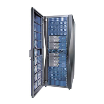
Page 93: Figure 2-1 Example Of Sgi Origin 350 Server Systems
Physical Features 39U rack 17U rack Example of SGI Origin 350 Server Systems Figure 2-1 007-4566-001... -
Page 94: Functional Architecture
2: System Overview Functional Architecture The Origin 350 server system is based on the SGI NUMAflex architecture, which is the third-generation shared-memory system architecture that is the basis of SGI HPC servers and supercomputers. The NUMAflex architecture is specifically engineered to provide technical professionals with superior performance and scalability in a design that is easy to deploy, program, and manage. - Page 95 Functional Architecture The Origin 350 server system can be configured with or without a NUMAlink module. When the system does not have a NUMAlink module, the system can contain from 2 to 8 processors. When the system does have a NUMAlink module, the system can contain from 4 to 32 processors.
-
Page 96: Figure 2-2 Base Compute Module Connected To An Expansion Compute
2: System Overview may or may not contain an IO9 PCI card and the devices and connector ports the IO9 card supports. Note: Each system requires one IO9 PCI card; this required card resides in the base compute module. The system can contain additional IO9 cards that reside in the expansion compute modules;... -
Page 97: Figure 2-3 Compute Modules Connected Via A Numalink Module
Functional Architecture When the system consists of a base compute module only, the maximum number of processors 4. To increase the number of processors in the system, the base compute module can connect to one or more expansion compute modules. When a system has more than two compute modules, a NUMAlink module is required. -
Page 98: Figure 2-4 Base Compute Module Connected To An Mpx Module
2: System Overview To increase the amount of memory in the system, the compute modules can connect to a memory and PCI expansion (MPX) module as shown in Figure 2-4.The MPX module is a 2U AC-powered device that can have from 1 GB to 8 GB of memory. This module also has four PCI/PCI-X slots. - Page 99 Functional Architecture The MPX and PCI expansion modules are peer-attached devices; they connect to the compute module via the NUMAlink connector. If the system has a NUMAlink module, the MPX and PCI expansion modules connect to the compute modules via the NUMAlink module (see Figure 2-5).
-
Page 100: Figure 2-5 Connection Of Mpx And Pci Expansion Modules To Compute Modules Via Numalink Module
2: System Overview 4-processor 4-processor Expansion compute module Expansion compute module MPX module MPX module NUMAlink module Port 7 Port 8 Port 6 Port 1 Router ASIC Port 5 Port 2 Port 4 Port 3 4-processor 4-processor Base compute module Expansion compute module PCI expansion module PCI expansion module... -
Page 101: System Configurations
System Configurations System Configurations The Origin 350 server system can be configured with or without a NUMAlink module. If the system does not have a NUMAlink module, this configuration is referred to as a base configuration. If the system has a NUMAlink module, it is referred to as a NUMAlink configuration. -
Page 102: Base Configuration
PCI expansion module or one MPX module to your system. If space is available in the rack, you can also add SGI TP900 storage modules to your system or you can add additional storage racks to your system. -
Page 103: Figure 2-6 Examples Of Base Configurations In 17U And 39U Racks
System Configurations Expansion compute module Base compute module Expansion compute module TP900 storage module Base compute module TP900 storage module Expansion compute module Expansion compute module Base compute module Base compute module PCI expansion module PCI expansion module Base compute module Base compute module Power bay module Power bay module... -
Page 104: Numalink Configuration
17U rack can house only one NUMAlink module, one base compute module, and up to five expansion compute modules. The 39U rack can house one or two Origin 350 server systems, as shown in Figure 2-7. In addition to the base and expansion compute modules, a NUMAlink configuration supports the following PCI expansion devices: the MPX module and the PCI expansion module. -
Page 105: Figure 2-7 Examples Of Numalink Configurations In 17U And 39U Racks
System Configurations Expansion compute module Expansion compute module Expansion compute module Expansion compute module NUMAlink module Expansion compute module Expansion compute module Expansion compute module Base compute module Expansion compute module Expansion compute module Expansion compute module TP900 storage module Expansion compute module NUMAlink module Expansion compute module... -
Page 106: System Components
2: System Overview System Components This section lists the major system components of a base configuration and a NUMAlink configuration, and briefly describes several of these components, in the following subsections: • “Major Components of a Base Configuration” on page 80 •... -
Page 107: Major Components Of A Numalink Configuration
SCSI connections in the system; each TP900 requires one SCSI connection.) • 2Gb SGI TP9100 storage system, SGI TP9400 storage system, or SGI TP9500 storage system (optional). Major Components of a NUMAlink Configuration The NUMAlink configuration can contain the following major components (see Figure 2-8): •... -
Page 108: Figure 2-8 Component Example Of Numalink Configuration
One or more TP900 storage modules (optional). (The maximum number of TP900s is dependent on the number of SCSI connections in the system; each TP900 requires one SCSI connection.) • 2Gb SGI TP9100 storage system, SGI TP9400 storage system, or SGI TP9500 storage system (optional). Compute modules NUMAlink module... -
Page 109: Compute Module
System Components Compute Module The compute module is a 2U AC-powered device that consists of the following: • Two or four 64-bit MIPS RISC processors. • 4 MB of secondary cache per processor. • 1 GB to 8 GB of memory. •... -
Page 110: Figure 2-9 Front And Rear Views Of Compute Module
2: System Overview Figure 2-9 shows the front and rear views of an Origin 350 compute module. See Chapter 3, “Compute Module,” for more information about this module. Front view Rear view Front and Rear Views of Compute Module Figure 2-9... -
Page 111: Numalink Module
System Components NUMAlink Module The NUMAlink module, shown in Figure 2-10, is a 2U AC-powered device that transfers messages between the compute modules via the NUMAlink 3 interconnect. This module is required for systems that contain more than two compute modules. The NUMAlink module consists of eight ports;... -
Page 112: Mpx Module
2: System Overview MPX Module The memory and PCI expansion (MPX) module is a 2U AC-powered device that has 1 GB to 8 GB of memory and four PCI/PCI-X slots (see Figure 2-11). You can add one MPX module to a base configuration that contains one base compute module. In a NUMAlink configuration, you can add up to four MPX modules. -
Page 113: Pci Expansion Devices
System Components PCI Expansion Devices A compute module contains four PCI/PCI-X slots; however, the base compute module has only two PCI/PCI-X slots and one PCI slot available because the lowermost slot is reserved for the IO9 PCI 66 MHz card, and the slot immediately above where the IO9 card is installed can only support PCI cards that run at a speed of 66 MHz or slower. -
Page 114: Figure 2-12 Pci Expansion Module
2: System Overview • You can add two PCI expansion modules to a system that contains two to six compute modules. • You can add three PCI expansion modules to a system that contains three to five compute modules. • You can add four PCI expansion modules to a system that contains four compute modules. -
Page 115: Storage Expansion
• For a SCSI (small computer system interface) JBOD (just a bunch of disks) solution, SGI offers the TP900 storage module, or SCSI disks can be added to expansion compute modules. Note: Adding SCSI disks to an expansion compute module requires an IO9 PCI card. -
Page 116: Sgi Tp900 Storage Module
2: System Overview • The Origin 350 server system also supports a number of tape devices. The various storage devices are discussed in the subsections that follow. SGI TP900 Storage Module The TP900 storage module, shown in Figure 2-14, is a 2U-high 8-drive storage system that provides compact, high-capacity, high-availability JBOD storage. -
Page 117: 2Gb Sgi Tp9100 Storage System
You can start with a basic JBOD configuration and later add RAID controllers, or you can start with a RAID configuration. The 2Gb SGI TP9100 storage system connects to the compute module via a Fibre Channel PCI card. For more information about the SGI TP9100 storage system, see SGI Total Performance 9100 (2 Gb TP9100) Storage System User’s Guide (007-4522-00x). -
Page 118: Figure 2-15 2Gb Sgi Tp9100 Storage System
Figure 2-15 2Gb SGI TP9100 Storage System 007-4566-001... -
Page 119: Sgi Tp9400 And Sgi Tp9500 Storage Systems
System Components SGI TP9400 and SGI TP9500 Storage Systems The SGI TP9400, shown in Figure 2-16, and the SGI TP9500 are highly scalable RAID storage subsystems. These storage systems have vast storage capacities and can grow to whatever size you require without disruption to normal processing activities. This continuous availability enables all active components to be configured redundantly and... -
Page 120: Tape Devices
2: System Overview Tape Devices The Origin 350 server systems support the following tape drives: • DLT 8000 - 8000 native (6-MB/s transfer rate, 40-GB storage capacity) • DLT 8000 - 7000 emulation (5-MB/s transfer rate, 35-GB storage capacity) •... -
Page 121: Table 2-2 Supported Tape Drive Subsystems
System Components Supported Tape Drive Subsystems Table 2-2 Tape Marketing Library Interface Media Drive GB/hr Average HSM or Drive Code Capacity Speed Access Backup Time in Seconds DLT 8000 3100157251 L20/L40/L80 SCSI 40 GB 6 MB/s 21.6 Backup (8000 3100157202 L180/L700 SCSI 40 GB... - Page 122 2: System Overview Supported Tape Drive Subsystems (continued) Table 2-2 Tape Marketing Library Interface Media Drive GB/hr Average HSM or Drive Code Capacity Speed Access Backup Time in Seconds T9840 3100140007 L180/L700 SCSI 20 GB 10 MB/s 3100140008 9740/9310 20 GB 10 MB/s 3100140001 9740/9310...
-
Page 123: L2 Controller
System Components L2 Controller The L2 controller, which is shown in Figure 2-17, is a rack-level controller that performs the following functions: • Controls resource sharing. • Controls L1 controllers. • Maintains system configuration and topology information. • Enables remote maintenance. •... -
Page 124: Figure 2-18 System Control For Base Configuration
2: System Overview Ethernet SGIconsole RS-232 NUMAlink (RS-422 signals used) Compute module Compute module EL-16 Console port Figure 2-18 System Control for Base Configuration SGIconsole L2 controller NUMAlink module USB hub Compute module Compute module Compute module Compute module Ethernet Compute module Compute module NUMAlink (USB signals used) -
Page 125: Usb Hub
Figure 2-20 USB Hub Power Components The Origin 350 server system can consist of the following power components: • One or two power distribution units (PDUs) (see Figure 2-21). The second PDU is added to the system when more than 15 AC power receptacles are needed within the rack. -
Page 126: Figure 2-21 Power Distribution Unit And Power Strip
2: System Overview Power distribution unit (PDU) Power strip Output receptacles Wall power source Input receptacle Circuit breaker and switch Figure 2-21 Power Distribution Unit and Power Strip • Power supply. The L2 controller receives power from a power supply that is attached to the side of the rack. -
Page 127: Figure 2-22 Power Bay Module
System Components Front view Rear view AC input connectors Power supplies 48-VDC and 12-VDC output connectors Power Bay Module Figure 2-22 Figure 2-23 shows the power connections for a sample Origin 350 server system. 007-4566-001... -
Page 128: Figure 2-23 Power Connections For A Sample Origin 350 Server System
I.D .R AN GE TP UT FA UL CH AN NE L CH AN NE L I.D .R AN GE TP UT FA UL Power bay Wall power source Power Connections for a Sample Origin 350 Server System Figure 2-23 007-4566-001... -
Page 129: Rack
System Components Rack The Origin 350 server system supports two rack types: a short rack and a tall rack. The racks are measured in standard units (U); one U is equal to 1.75 in. (4.45 cm). The short rack is a 17U rack and the tall rack is a 39U rack (see Figure 2-24). -
Page 130: Figure 2-25 Slide Mounting Rails
2: System Overview Both rack types are industry-standard 19-inch racks, and they support two types of mounting rails (slide rails and shelf rails - also known as fixed rails) that hold the modules within the rack. For example, the compute modules use slide mounting rails (see Figure 2-25). -
Page 131: Figure 2-26 L-Shaped Mounting Rails (Shelf Rails)
System Components L-shaped horizontal mounting rails 19 in. Figure 2-26 L-shaped Mounting Rails (Shelf Rails) Both rack types, as shown in Figure 2-27, have front and rear doors that have keylocks to prevent unauthorized access of the system. The racks also have cable entry/exit areas at the bottom of the racks and cable management hardware in the rear of the racks. -
Page 132: Figure 2-27 Front Views Of Short And Tall Racks
2: System Overview 39U rack 17U rack Figure 2-27 Front Views of Short and Tall Racks 007-4566-001... -
Page 133: Compute Module
“System Configuration” on page 126 • “Technical Specifications” on page 130 Two types of compute modules are available for the SGI 350 server system, as follows: • Base compute module. This module is your system’s primary compute module where your server system’s operating system resides. (Every system must have a base compute module.) The base compute module provides processors, memory,... -
Page 134: System Features
3: Compute Module System Features This 2U base compute module can serve as a standalone Origin 350 server system, or it can be rackmounted with other optional modules to create an Origin 350 server system with more functionality. The base compute module consists of 2 to 4 64-bit MIPS RISC (reduced instruction set computer) processors and from 1 to 8 GB of local memory available on two to eight dual inline memory modules (DIMMs). -
Page 135: Figure 3-1 Front And Side Views Of A Compute Module
System Features Figure 3-1 Front and Side Views of a Compute Module The compute module includes the following features: • L1 controller, which manages and monitors functions of the compute module such as system temperature. The module includes an L1 controller display, which displays system processes and error messages. - Page 136 10/100/1000 BaseT Ethernet port. – 68-pin VHDCI Ultra3 SCSI connector. Table 3-1 compares an Origin 300 server system with an Origin 350 server system, and highlights the expanded functionality of the compute module. Table 3-1 Comparing Origin 300 Server System with Origin 350 Server System...
- Page 137 System Features Comparing Origin 300 Server System with Origin 350 Server System (continued) Table 3-1 System Feature Origin 300 Server System Origin 350 Server System I/O expansion slots Two 64-bit slots for 33 MHz or 66 Three 64-bit slots for 33 MHz or 66 MHz PCI cards.
- Page 138 3: Compute Module The compute module architecture includes the following components, which are shown in Figure 3-2 on page 113 and discussed in the following subsections: • “IP53 Node Board” on page 114 • “IO9 Card” on page 119 • “Interface Board with a Daughtercard”...
-
Page 139: Figure 3-2 Block Diagram Of Base Compute Module
System Features DVD-ROM SCSI NVRAM Disk drive IOC-4 10/100/1000BaseT Ethernet SCSI 160 Disk drive RTI out Ethernet RTI in IO9 PCI card riser ASIC control L1 display PCI riser card NUMAlink 3 IP53 node board connector DIMM Processor C L2 cache DIMM Processor D DIMM... -
Page 140: Ip53 Node Board
3: Compute Module IP53 Node Board The IP53 node board consists of the following components, most of which are discussed in the subsections that follow. • Two or four MIPS RISC processors (labeled CPU in Figure 3-3). Each processor has a secondary L2 cache. -
Page 141: Processors (Cpus)
System Features MegArray connector SRAM DIMM 1.1-V to 1.8-V Vcpu VRMs Bedrock 1.5-V V i/o 2.5-V Vmem Figure 3-3 IP53 Node Board Processors (CPUs) The R16000 processors, which are soldered to the IP53 node board, implement the 64-bit MIPS IV instruction set architecture. The architecture gathers and decodes four instructions per cycle and issues the instructions to five fully pipelined execution units. -
Page 142: Primary And Secondary Cache
3: Compute Module Primary and Secondary Cache To reduce memory latency, a processor has access to two on-chip 32-KB L1 (primary) caches (one cache is for data and the other cache is for instructions) and an off-chip L2 (secondary) cache. The L1 caches are located within the processor for fast, low-latency access of instructions and data. -
Page 143: Table 3-2 Dimms And Bank Pairs
System Features Table 3-2 lists the DIMM slots and the corresponding bank pairs to which local memory is provided when DIMMs are installed: DIMMs and Bank Pairs Table 3-2 DIMM in Slot Provides Local Memory for Number Bank Pair Numbers 0 and 1 0 and 1 2 and 3... -
Page 144: Figure 3-4 Local Memory Layout
3: Compute Module DIMM slot 0 Banks 0 and 1 DIMM slot 2 Banks 2 and 3 DIMM slot 4 Banks 4 and 5 DIMM slot 6 Banks 6 and 7 1.1-V to 1.8-V VRM Bedrock 1.5-V VRM 2.5-V VRM DIMM slot 1 Banks 0 and 1 DIMM slot 3... -
Page 145: Bedrock Asic
System Features Bedrock ASIC The Bedrock ASIC enables communication among the processors, memory, network, and I/O devices. It controls all activity within the node board (for example, error correction and cache coherency). The Bedrock ASIC also supports page migration. The Bedrock ASIC consists of the following: •... -
Page 146: Interface Board With A Daughtercard
3: Compute Module The IO9 card also contains an IOC-4 ASIC that supports the following features: • One IDE channel for the DVD-ROM. • Four serial ports. • Two PS/2 ports for keyboard and mouse connections. Note: The PS/2 ports and three serial ports are located on a daughtercard that is only available on a base compute module. -
Page 147: Dvd-Rom
System Features DVD-ROM The compute module can contain an optional slim-line DVD-ROM that has CD-ROM capabilities. Note: The DVD-ROM requires an IO9 PCI card. The DVD-ROM is located at the front left side of the module (above the disk drives). Disk Drives The base compute module supports one or two sled-mounted Ultra3 SCSI disk drives that have a peak data transfer speed of up to 160 MB/s between the disks and system... -
Page 148: Power Supplies
3: Compute Module Power Supplies The compute module can contain one or two power supplies; the second power supply is optional and is required only when the customer wants redundant power. The power supply can input 110/220 VAC and output 500 W (12 VDC, 5 VDC, and -12 VDC. Both power supplies are hot-swappable. - Page 149 • L1 controller display. A liquid crystal display (LCD) displays status and error messages that the L1 controller generates. Note: See the SGI L1 and L2 Controller Software User’s Guide (007-3938-00x) for more information on the L1 controller. • Power button with LED. Press this button to power on the internal components.
-
Page 150: Rear Panel Items
3: Compute Module Rear Panel Items This section describes the rear panel connectors, PCI/PCI-X slots, and LEDs of the compute module, as shown in Figure 3-6. Keyboard Mouse PCI/PCI-X slots: Bus 2, PCI 4 slot 2 (PCI 4) Bus 2, PCI 3 slot 1 (PCI 3) CONSOLE... - Page 151 These 64-bit slots can contain 33-MHz and 66-MHz PCI cards, and 66-MHz and 100-MHz PCI-X cards. (For an updated list of supported cards, see SGI Supportfolio at http://support.sgi.com.) The bottom-most slot contains an IO9 PCI card in the base compute module.
-
Page 152: System Configuration
This section also lists external compute module configuration options that can enhance the performance of the Origin 350 server system. For example, the compute module can connect to a 2U TP900 storage system to expand storage, or it can connect to a PCI expansion module to increase I/O capabilities. -
Page 153: External Configurations
The NUMAlink module connects two or more compute modules. See Chapter 5, “NUMAlink Module,” for more information about this module. The Origin 350 server system can be configured in many different ways to satisfy your computing needs. This section shows two sample configurations. -
Page 154: Figure 3-7 System With One Base Compute Module And One Mpx Module
3: Compute Module Figure 3-7 shows an Origin 350 server system on a table top that includes the following items: • A 2U base compute module has 4 processors, 8 GB of local memory, and three PCI/PCI-X card slots. The fourth lowermost PCI/PCI-X slot comes with a factory-installed IO9 PCI card. -
Page 155: Figure 3-8 System With A Pci Expansion Module, An Mpx Module, A Numalink Module, A System Expansion Compute Module, And A Base Compute Module
System Configuration Figure 3-8 shows an Origin 350 server system rackmounted in a 17U rack that includes the following items (from top to bottom in the rack): • A 4U PCI expansion module adds 12 PCI card slots to the server system. -
Page 156: Technical Specifications
3: Compute Module Technical Specifications Table 3-4 lists the bandwidth characteristics of the compute module. Table 3-4 Bandwidth Characteristics of the Compute Module Characteristic Peak Bandwidth Sustainable Bandwidth NUMAlink channel 3.2 GB/s full duplex ~1420 MB/s each direction 1.6 GB/s each direction Xtown2 channel 2.4 GB/s full duplex ~1066 MB/s half duplex... -
Page 157: Table 3-5 General Features Of The Compute Module
Technical Specifications General Features of the Compute Module (continued) Table 3-5 Feature Base Compute Module Expansion Compute Module L1 port (USB, type B) Serial port PS/2 port 1 keyboard and 1 mouse RT interrupt input port RT interrupt output port Ethernet port One 10BaseT/100BaseT/1000BaseT SCSI port (internal) -
Page 159: Memory And Pci Expansion (Mpx) Module
Chapter 4 Memory and PCI Expansion (MPX) Module This chapter describes the function and physical components of the 2U-high SGI memory and expansion (MPX) module, which can add local memory (DIMMs) and four PCI/PCI-X card slots to your system. Specifically, this chapter includes the following information: •... -
Page 160: Figure 4-1 Front And Side Views Of Mpx Module
4: Memory and PCI Expansion (MPX) Module Figure 4-1 Front and Side Views of MPX Module The MPX module includes the following features: • The L1 controller manages and monitors the functions of the MPX module, such as system temperature. The system includes an L1 controller display system that processes error messages. -
Page 161: Ip53 Node Board
System Features The MPX module architecture includes the components discussed in the following subsections • “IP53 Node Board” on page 135 • “Interface Board” on page 138 • “PCI Riser Card” on page 138 • “Power Supplies” on page 139 IP53 Node Board The IP53 node board consists of the following components: •... -
Page 162: Table 4-1 Dimm Slots And Corresponding Bank Pairs
4: Memory and PCI Expansion (MPX) Module For example, if you install a DIMM in slot 0, you must also install a DIMM in slot 1 to provide local memory for bank pair 0 and 1. And conversely, if you remove a DIMM from slot 0, you must also remove a DIMM from slot 1 in order to remove local memory from bank pair 0 and 1. -
Page 163: Figure 4-2 Local Memory Layout
System Features Slot 7 Banks 6 and 7 Slot 5 Banks 4 and 5 Slot 3 Banks 2 and 3 Slot 1 Banks 0 and 1 Slot 6 Banks 6 and 7 Slot 4 Banks 4 and 5 Slot 2 Banks 2 and 3 Slot 0 Banks 0 and 1 Figure 4-2 Local Memory Layout... -
Page 164: Bedrock Asic
4: Memory and PCI Expansion (MPX) Module Bedrock ASIC The Bedrock ASIC enables communication among the memory, network, and I/O devices. It controls all activity within the node board; for example, error correction and cache coherency. The Bedrock ASIC also supports page migration. The Bedrock ASIC consists of the following:] •... -
Page 165: Power Supplies
External Components Power Supplies The MPX module can contain one or two power supplies; the second power supply is optional and is required only when you want redundant power. The power supply can input 110/220 VAC and output 500 W (12 VDC, 5 VDC, and -12 VDC). Both power supplies are hot-swappable. -
Page 166: Rear Panel Items
• L1 controller display. A liquid crystal display (LCD) displays status and error messages that the L1 controller generates. Note: See the SGI L1 and L2 Controller Software User’s Guide (007-3938-00x) for more information on the L1 controller. • Power button with LED. Press this button to power on the internal components. -
Page 167: Figure 4-4 Rear Panel Items
External Components CONSOLE port Bus 2, slot 2 (PCI 4) Bus 2, slot 1 (PCI 3) Bus 1, slot 2 (PCI 2) Bus 1, slot 1 (PCI 1) L1 port XIO connector NUMAlink connector Serial port Figure 4-4 Rear Panel Items The rear panel of the MPX module has the following items: •... -
Page 168: System Configurations
This section also lists external MPX module configuration options that can enhance the performance of the Origin 350 server system. For example, the a server system configuration can include an MPX module together with a base compute module, a 2U SGI TP900 storage system to expand storage, and a PCI expansion module to increase I/O capabilities. -
Page 169: External Configurations
The NUMAlink module connects two or more modules. See Chapter 5, “NUMAlink Module,” for information about this module. The Origin 350 server system can be configured with an MPX module in many different ways to satisfy your computing needs. This section shows two sample configurations. -
Page 170: Figure 4-5 System With One Mpx Module And One Base Compute Module
4: Memory and PCI Expansion (MPX) Module Figure 4-5 shows an Origin 350 server system on a table top that includes the following items: • An MPX module adds 8 GB of local memory and four PCI/PCI-X card slots to your system. -
Page 171: Figure 4-6 System With Pci Expansion Module, Mpx Module, Numalink
System Configurations Figure 4-6 shows an Origin 350 server system rackmounted in a 17U rack that includes the following items (from top to bottom in the rack): • A 4U PCI expansion module adds 12 PCI card slots to the server system. -
Page 172: Technical Specifications
4: Memory and PCI Expansion (MPX) Module Technical Specifications Table 4-3 lists the bandwidth characteristics of the MPX module. Table 4-3 Bandwidth Characteristics of the MPX Module Characteristic Peak Bandwidth Sustainable Bandwidth NUMAlink channel 3.2 GB/s full duplex ~1420 MB/s each direction 1.6 GB/s each direction Xtown2 channel 2.4 GB/s full duplex... -
Page 173: Numalink Module
Chapter 5 NUMAlink Module This chapter describes the function and physical components of the NUMAlink module in the following sections: • “Overview” on page 147 • “External Components” on page 149 • “Technical Specifications” on page 153 Overview The NUMAlink module is a high-speed switch that routes network packets between compute modules, MPX modules, and PCI expansion modules. -
Page 174: Figure 5-1 Block Diagram Of Numalink Module
The NUMAlink module has the following features: • SGI custom-designed router ASIC, which is an eight-port crossbar that connects any input-link channel to any of the seven possible output-link channels (see Figure 5-1). The NUMAlink channels operate at 1.6 GB/s (each direction). -
Page 175: External Components
L1 display. The L1 display is a 55.7 mm x 32 mm backlit liquid crystal display (LCD) that displays system messages. It displays two lines with a maximum of 12 characters on each line. Note: See the SGI L1 and L2 Controller Software User’s Guide (007-3938-00x) for more information about the L1 controller. •... -
Page 176: Figure 5-2 Front View Of Numalink Module
5: NUMAlink Module Service-required LED Fans Display Service Failure On/Off switch with LED Failure LED Figure 5-2 Front View of NUMAlink Module 007-4566-001... -
Page 177: Rear Panel Components
External Components Rear Panel Components The NUMAlink module has the following rear panel items (see Figure 5-3): • Power connector. This connector connects the NUMAlink module to a power distribution unit or power strip via a power cable. • LINKS R TO R connectors (1, 6, 7, and 8, or A, F, G, and H). These link connectors connect the NUMAlink module to compute modules and/or MPX modules. -
Page 178: Figure 5-3 Rear View Of Numalink Module
5: NUMAlink Module Ports 1, 6, 7, and 8 can connect to compute L1 port LINK connector LEDs or MPX modules LINKS R TO R L1 PORT LINKS R TO R C TO R Ports 2, 3, 4, and 5 Power connector can connect to compute, MPX, or PCI expansion... -
Page 179: Technical Specifications
Technical Specifications Technical Specifications Table 5-1 lists the technical specifications of the NUMAlink module. Table 5-1 NUMAlink Module Technical Specifications Characteristic Specification Height 3.3 in. (83.82 mm) Width 17.38 in. (441.45 mm) Depth 27.5 in. (698.50 mm) Weight 20 lb (9.1 kg) Input power 110/220 VAC (~ 60 W) Table 5-2 lists the specifications of the NUMAlink module ports. -
Page 181: Installing And Removing Customer-Replaceable Units
Chapter 6 Installing and Removing Customer-replaceable Units This chapter provides safety instructions to follow when using and maintaining your system. It also describes how to install and remove module customer-replaceable units (CRUs). This information is covered in the following sections: •... - Page 182 Do not allow anything to rest on the power cord. Do not locate this product where people will walk on the cord. • Do not use extension cords with your SGI system. • Never push objects of any kind into this product through cabinet slots because they may touch dangerous voltage points or short out parts that could result in a fire or...
-
Page 183: Pci And Pci-X Cards
PCI-X cards. The following instructions, which describe how to install and remove a PCI or PCI-X card from an Origin 350 server system base compute module, can be used to install and remove PCI and PCI-X cards from the expansion compute module and a memory and PCI expansion (MPX) module. -
Page 184: Rules For Card Installation And Removal
6: Installing and Removing Customer-replaceable Units Rules for Card Installation and Removal When installing or removing PCI or PCI-X cards from your system, be aware of the following rules: • If you run a PCI and PCI-X cards on the same bus at the same time, the PCI-X card will run on PCI mode. -
Page 185: Figure 6-2 Opening The Cover To Install The Card
PCI and PCI-X Cards Warning: Components may be hot. To avoid injury, allow the components to cool for approximately five minutes before you proceed with these instructions. 3. If your module is rackmounted, remove the two screws that secure the module to the front rails of the rack. -
Page 186: Figure 6-3 Removing The Chassis Rail
Caution: Your system may or may not have a factory-installed IO9 card, which always comes installed in the lowermost slot. To prevent damage to your system, only a trained SGI service support engineer can install or remove an IO9 card. Removing the Chassis Rail... -
Page 187: Figure 6-4 Removing The Lower Pci/Pci-X Support Bracket
PCI and PCI-X Cards 8. If you are installing a card in one of the two lowermost card slots, you must also remove the lower PCI/PCI-X support bracket that covers the two lowermost slots, as shown in Figure 6-4, by removing the four Phillips screws. Figure 6-4 Removing the Lower PCI/PCI-X Support Bracket 007-4566-001... -
Page 188: Figure 6-5 Removing Blanking Plate
6: Installing and Removing Customer-replaceable Units 9. If a blanking plate covers the slot that is needed for the installation, remove the retaining screw, as shown in Figure 6-5, and the blanking plate. Figure 6-5 Removing Blanking Plate 007-4566-001... -
Page 189: Figure 6-6 Installing The Card And Installing The Retaining Screw
PCI and PCI-X Cards 10. Insert the card into the slot by pushing the card into the connector until it is properly seated and install the retaining screw, as shown in Figure 6-6. If you have installed the card into one of the upper two slots, proceed to step 13. Installing the Card and Installing the Retaining Screw Figure 6-6 007-4566-001... -
Page 190: Figure 6-7 Replacing The Lower Pci/Pci-X Support Bracket
6: Installing and Removing Customer-replaceable Units 11. If you have installed a card in one of the two bottom-most card slots, replace the lower PCI/PCI-X support bracket that covers the two bottom-most slots and screw in the four Phillips screws, as shown in Figure 6-7. Figure 6-7 Replacing the Lower PCI/PCI-X Support Bracket 007-4566-001... -
Page 191: Figure 6-8 Replacing The Chassis Rail
PCI and PCI-X Cards 12. Replace the chassis rail by screwing in the five Phillips screws, as shown in Figure 6-8. Figure 6-8 Replacing the Chassis Rail 007-4566-001... -
Page 192: Figure 6-9 Closing The Cover
6: Installing and Removing Customer-replaceable Units 13. Close the hinged cover on the system and screw in the ten Phillips screws to secure the cover, as shown in Figure 6-9. Figure 6-9 Closing the Cover 14. If you removed the module from the rack, perform the following substeps. (If you have not removed the module from the rack, proceed to step 15.) Fully extend the left and right slide rails from the rack until they lock into place. -
Page 193: Removing A Card
PCI and PCI-X Cards Removing a Card To remove a PCI or PCI-X card, follow these steps: Power off the server system. For powering off instructions, see “Powering the Server System On and Off” on page 53. 2. Disconnect all of the cables at the rear of the module. Warning: Components may be hot. -
Page 194: Figure 6-10 Opening The Cover To Remove The Card
6: Installing and Removing Customer-replaceable Units 6. To access the card, remove the ten Phillips screws, as shown in Figure 6-10, and lift the hinged cover. Figure 6-10 Opening the Cover to Remove the Card 007-4566-001... -
Page 195: Figure 6-11 Removing The Chassis Rail
PCI/PCI-X card from one of the two lowermost card slots, proceed to step 9.) Caution: Only a trained SGI service support engineer can install and remove an IO9 card. Otherwise, your system could be damaged. Therefore, if an IO9 card is installed in your system (it is always installed in the lowermost slot), you can remove a card only from the upper three slots. -
Page 196: Figure 6-12 Removing The Lower Pci/Pci-X Support Bracket
6: Installing and Removing Customer-replaceable Units 8. If you are removing a card from one of the two lowermost slots, you must also remove the lower PCI/PCI-X support bracket that covers the two lowermost slots by unscrewing the four Phillips screws, as shown in Figure 6-12. Removing the Lower PCI/PCI-X Support Bracket Figure 6-12 007-4566-001... -
Page 197: Figure 6-13 Removing The Retaining Screw And Extracting The Card
PCI and PCI-X Cards 9. Unscrew the retaining screw from the card that you will remove, and extract the card, as shown in Figure 6-13. Place the card on an ESD-safe surface. Figure 6-13 Removing the Retaining Screw and Extracting the Card 007-4566-001... -
Page 198: Figure 6-14 Placing A Blanking Plate
6: Installing and Removing Customer-replaceable Units 10. If you are replacing the card that you have removed, proceed to step 10 of “Installing a Card” on page 158. If you are not replacing the card that you have removed, proceed to the next step. 11. -
Page 199: Figure 6-15 Replacing The Lower Pci/Pci-X Support Bracket
PCI and PCI-X Cards 12. If you have removed a card from one of the two bottom-most card slots, replace the lower PCI/PCI-X support bracket that covers the two bottom-most slots, and screw in the four Phillips screws, as shown in Figure 6-15. Figure 6-15 Replacing the Lower PCI/PCI-X Support Bracket 007-4566-001... -
Page 200: Figure 6-16 Replacing The Chassis Rail
6: Installing and Removing Customer-replaceable Units 13. Replace the chassis rail, by screwing the five Phillips screws, as shown in Figure 6-16. Replacing the Chassis Rail Figure 6-16 007-4566-001... -
Page 201: Figure 6-17 Close And Screw Down Cover
PCI and PCI-X Cards 14. Close the hinged cover on the system and screw in the ten Phillips screws to secure the cover, as shown in Figure 6-17. Figure 6-17 Close and Screw Down Cover 15. If you removed the module from the rack, follow these substeps. (If you have not removed the module from the rack, proceed to step 16.) Fully extend the left and right slide rails from the rack until they lock into place. -
Page 202: Disk Drives
6: Installing and Removing Customer-replaceable Units Disk Drives Each base compute module of an Origin 350 server system can contain one or two sled-mounted Ultra3 SCSI disk drives (see Figure 6-18). Note: A system expansion compute module, or an MPX module, may or may not contain disk drives. -
Page 203: Installing A Disk Drive
Disk Drives Installing a Disk Drive To install a disk drive, follow these steps: Open the bezel door as far as it will open. Position the drive assembly so that it engages the bay guide rails and, with the locking handle fully swung open, gently push the drive into the bay until the locking handle engages with left side of the bay opening, as shown in Figure 6-19A. -
Page 204: Figure 6-19 Installing A Disk Drive
6: Installing and Removing Customer-replaceable Units Installing a Disk Drive Figure 6-19 007-4566-001... -
Page 205: Removing A Disk Drive
Disk Drives Removing a Disk Drive To remove a disk drive, follow these steps: If you are replacing a data drive, ensure that the drive has spun down before you remove it. 2. If you are replacing the system drive, you must first power off the server system. For instructions to power off the server system, see “Powering the Server System On and Off”... -
Page 206: Figure 6-20 Removing A Disk Drive
6: Installing and Removing Customer-replaceable Units Figure 6-20 Removing a Disk Drive 007-4566-001... -
Page 207: Power Supplies
Power Supplies Power Supplies Each Origin 350 server system compute module and MPX module can contain one or two sled-mounted power supplies (refer to Figure 6-21). The second is a redundant power supply to assure that your system always has power. -
Page 208: Reading The Power Supply Leds
6: Installing and Removing Customer-replaceable Units Reading the Power Supply LEDs Use the LED located on the front (towards the top) of the power supply to read the condition of the power supply. Table 6-1 shows the LED status and the power supply condition the LED status indicates. - Page 209 Power Supplies b. Swing open the screen cover as shown in Figure 6-22B. Disengage the power supply from the power supply bay by pushing the interior release button to the right and pulling up and out on the green-colored handle lock as shown in Figure 6-22C. d.
-
Page 210: Figure 6-22 Removing A Power Supply
6: Installing and Removing Customer-replaceable Units Ribbon cable Figure 6-22 Removing a Power Supply 007-4566-001... -
Page 211: Figure 6-23 Installing The Power Supply
Power Supplies Ribbon cable Screen cover Bezel door Installing the power supply Figure 6-23 007-4566-001... -
Page 212: Memory
Memory Memory is contained on cards that are referred to as DIMMs (dual inline memory modules). Each Origin 350 server system base compute module, system expansion compute module, and MPX module can contain two, four, six, or eight DIMMs installed on eight DIMM slots located on the module. - Page 213 DIMMs in slots 6 and 7 to provide memory for banks 6 and 7. • The DIMMs used in the Origin 350 server system base compute module, the system expansion compute module, and the MPX module are not compatible with the DIMMs used in the Origin 200, SGI 2000 series, Onyx2, or Octane systems.
-
Page 214: Figure 6-24 Layout Of Dimm Slots And Local Memory Banks
6: Installing and Removing Customer-replaceable Units Slot 7 Banks 6 and 7 Slot 5 Banks 4 and 5 Slot 3 Banks 2 and 3 Slot 1 Banks 0 and 1 Slot 6 Banks 6 and 7 Slot 4 Banks 4 and 5 Slot 2 Banks 2 and 3 Slot 0 Banks 0 and 1 Figure 6-24... -
Page 215: Installing A Dimm
Memory Installing a DIMM To install a DIMM, follow these steps: Power off the server system. For powering off instructions, see “Powering the Server System On and Off” on page 53. 2. Disconnect all of the cables at the rear of the module. Warning: Components may be hot. -
Page 216: Figure 6-25 Opening Module Cover To Install Dimms
6: Installing and Removing Customer-replaceable Units 5. To access the DIMMs, remove the ten Phillips screws shown in Figure 6-25 and lift and open the hinged cover. Figure 6-25 Opening Module Cover to Install DIMMs 007-4566-001... -
Page 217: Figure 6-26 Removing The Plastic Air Baffle
Memory 6. Remove the plastic air baffle covering the DIMMs, as shown in Figure 6-26. Air baffle Removing the Plastic Air Baffle Figure 6-26 7. Install the DIMM, as follows (see Figure 6-27): Note: If you need to find the correct location in which to install the DIMMs, make sure to read the introductory material in “Memory”... -
Page 218: Figure 6-27 Inserting A Dimm
6: Installing and Removing Customer-replaceable Units 11. Install the two screws that secure the module to the front rails of the rack. 12. Install all of the cables at the rear of the module. 13. Power on the server system as described in “Powering the Server System On and Off”... -
Page 219: Removing A Dimm
Memory Removing a DIMM To remove a DIMM, follow these steps: Power off the server system. For powering off instructions, see “Powering the Server System On and Off” on page 53. 2. Disconnect all of the cables at the rear of the module. Warning: Components may be hot. -
Page 220: Figure 6-29 Removing The Plastic Air Baffle
6: Installing and Removing Customer-replaceable Units 6. Remove the plastic air baffle covering the DIMMs, as shown in Figure 6-29. Air baffle Figure 6-29 Removing the Plastic Air Baffle 7. Remove the DIMM, as follows (see Figure 6-30): Note: If you need to find the correct location from which to remove the DIMMs, make sure to read the introductory material in “Memory”... -
Page 221: Figure 6-30 Removing A Dimm
Memory 11. Press the safety latches on both sides of the module and slide the module into the rack. 12. Install the two screws that secure the module to the front rails of the rack. 13. Install all of the cables at the rear of the module. 14. -
Page 222: L1 Controller Display
The L1 controller, which is used to monitor and manage the base compute module of the Origin 350 server system, has a display located on the front panel of the base compute module as shown in Figure 6-31. Every Origin 350 server system module is factory- shipped with an L1 controller display. -
Page 223: Figure 6-32 Opening The Module To Access The L1 Controller Display
L1 Controller Display 5. To access the area where the L1 display is replaced, remove the ten Phillips screws shown in Figure 6-32, and lift and open the hinged cover. Figure 6-32 Opening the Module to Access the L1 Controller Display 6. -
Page 224: Figure 6-33 Removing The L1 Controller Display Panel
6: Installing and Removing Customer-replaceable Units Hook slots Figure 6-33 Removing the L1 Controller Display Panel 007-4566-001... - Page 225 L1 Controller Display 10. Connect the L1 controller cable to the connector on the new L1 controller display, making sure that the red stripe is to your left, as shown in Figure 6-34A. 11. Align the two screw holes on the L1 controller display with the holes on the L1 display protective cover, and screw in the two Phillips screws, as shown in Figure 6-34B.
-
Page 226: Figure 6-34 Installing An L1 Controller Display Panel
6: Installing and Removing Customer-replaceable Units Red stripe Hook slots Figure 6-34 Installing an L1 Controller Display Panel 14. Attach the hinged cover and secure it to the module with the ten Phillips screws. 15. Press the safety latches on both sides of the module, and slide the module into the rack. - Page 227 L1 Controller Display 17. Install all of the cables at the rear of the module. 18. Power on the server system as described in “Powering the Server System On and Off” on page 53. 007-4566-001...
-
Page 229: Troubleshooting
Chapter 7 Troubleshooting This chapter provides the following sections to help you troubleshoot your system: • “Troubleshooting Chart” on page 204 • “L1 Controller Error Messages” on page 206 • “SGI Electronic Support” on page 208 007-4566-001... -
Page 230: Troubleshooting Chart
Table 7-1 lists recommended actions for problems that can occur on your system. For problems that are not listed in this table, use the SGI Electronic Support system to help solve your problem or contact your SGI system support engineer (SSE). More information about the SGI Electronic Support system is provided later in this chapter. - Page 231 Troubleshooting Chart Troubleshooting Chart (continued) Table 7-1 Problem Description Recommended Action The system status LED of the TP900 is Contact your SSE. amber. The power status LED of the TP900 is Contact your SSE to replace the power supply amber. module.
-
Page 232: L1 Controller Error Messages
L1 Controller Error Messages Table 7-2 lists error messages that the L1 controller generates and displays on the L1 display. This display is located on the front of the Origin 350 base compute modules, the NUMAlink module, and the PCI expansion modules. - Page 233 L1 Controller Error Messages L1 Controller Messages (continued) Table 7-2 L1 System Controller Message Message Meaning and Action Needed Temperature messages: low alt. ATTN: TEMP # advisory temperature reached The ambient temperature at the module’s air @ xxC xxF inlet has exceeded 30 ºC. ATTN: TEMP # critical temperature reached The ambient temperature at the module’s air @ xxC xxF...
-
Page 234: Sgi Electronic Support
Figure 7-1 shows the sequence of events that occurs if you use all of the SGI Electronic Support capabilities. - Page 235 The sequence of events can be described as follows: Embedded Support Partner (ESP) monitors your system 24 hours a day. 2. When a specified system event is detected, ESP notifies SGI via e-mail (plain text or encrypted). 3. Applications that are running at SGI analyze the information, determine whether a support case should be opened, and open a case if necessary.
- Page 236 The following three components compose the integrated SGI Electronic Support system: SGI Embedded Support Partner (ESP) is a set of tools and utilities that are embedded in the IRIX operating system. ESP can monitor a single system or group of systems for system events, software and hardware failures, availability, performance, and configuration changes, and then perform actions based on those events.
-
Page 237: Technical Specifications
“PCI Expansion Module Specifications” on page 216 • “NUMAlink Module Specifications” on page 217 • “Rack Specifications” on page 218 • “SGI TP900 Storage Module Specifications” on page 219 • “Power Bay Module Specifications” on page 220 • “USB Hub Specifications” on page 221 •... -
Page 238: Environmental System Specifications
A: Technical Specifications Environmental System Specifications Table A-1 lists the environmental specifications of the Origin 350 server system. Table A-1 Environmental Specifications Characteristic Specification Temperature, +5 ºC (+41 ºF) to +35 ºC (+95 ºF) (up to 1500 m [5,000 ft]) operating +5 ºC (+41 ºF) to +30 ºC (+86 ºF) (1500 m to 3000 m [5,000 ft to 10,000 ft]) -
Page 239: Compute Module Specifications
Compute Module Specifications Compute Module Specifications Table A-2 lists the bandwidth characteristics of the compute module. Table A-2 Bandwidth Characteristics of the Compute Module Characteristic Peak Bandwidth Sustainable Bandwidth NUMAlink 3.2 GB/s full duplex ~1420 MB/s each direction channel 1.6 GB/s each direction Xtown2 channel 2.4 GB/s full duplex ~1066 MB/s half duplex... - Page 240 A: Technical Specifications General Features of the Compute Module (continued) Table A-3 Feature Base Compute Module Expansion Compute Module RT interrupt input port RT interrupt output port Ethernet port 1 10BaseT/100BaseT/1000BaseT SCSI port (external) 1 Ultra3 SCSI (VHDCI) SCSI port (internal) 1 Ultra3 SCSI, 160 MB/s 3.5-in.
-
Page 241: Mpx Module Specifications
MPX Module Specifications MPX Module Specifications Table A-5 lists the bandwidth characteristics of the MPX module. Table A-5 Bandwidth Characteristics of the MPX Module Characteristic Peak Bandwidth Sustainable Bandwidth NUMAlink 3.2 GB/s full duplex ~1420 MB/s each direction channel 1.6 GB/s each direction Xtown2 channel 2.4 GB/s full duplex ~1066 MB/s half duplex... -
Page 242: Pci Expansion Module Specifications
A: Technical Specifications PCI Expansion Module Specifications Table A-7 lists the bandwidth characteristics of the PCI expansion module. Table A-7 Bandwidth Characteristics of the PCI Expansion Module Characteristic Peak Bandwidth NUMAlink channel 1.2 GB/s each direction Table A-8 lists the specifications of the PCI expansion module. Table A-8 PCI Expansion Module Specifications Characteristic... -
Page 243: Numalink Module Specifications
NUMAlink Module Specifications NUMAlink Module Specifications Table A-9 lists the bandwidth characteristics of the NUMAlink module. Table A-9 Bandwidth Characteristics of the NUMAlink Module Characteristic Peak Bandwidth Sustainable Bandwidth NUMAlink channel 3.2 GB/s full duplex ~1420 MB/s each direction 1.6 GB/s each direction Table A-10 lists the specifications for the NUMAlink module, which requires 2U rack space. -
Page 244: Rack Specifications
A: Technical Specifications Rack Specifications The Origin 350 server system can be housed in short (17U) or tall (39U) racks. Note: One U is 1.75 in. (4.45 cm). Table A-12 lists the specifications of the short rack. Table A-12 Short Rack Specifications (with Skins) Characteristic Specification... -
Page 245: Sgi Tp900 Storage Module Specifications
SGI TP900 Storage Module Specifications SGI TP900 Storage Module Specifications Table A-14 lists the specifications of the SGI TP900 storage module. Table A-14 TP900 Storage Module Specifications Characteristic Specification Height 3.37 in. (85.7 mm) Width 17.6 in. (447 mm) Depth 21.46 in. -
Page 246: Power Bay Module Specifications
A: Technical Specifications Power Bay Module Specifications The power bay requires 3U amount of space within the rack. Table A-15 lists the specifications for the power bay. Table A-15 Power Bay Module Specifications Characteristic Specification Height 5.118 in. (130 mm) Width 17.5 in. -
Page 247: Usb Hub Specifications
USB Hub Specifications USB Hub Specifications Table A-17 lists the specifications of the USB hub. Table A-17 USB Hub Specifications Characteristic Specification Height 0.688 in. (17.475 mm) Width 2.5 in. (63.5 mm) Depth 3.25 in. (82.55 mm) Non-proprietary I/O Port Specifications This section provides pin assignment information for the non-proprietary connectors on the following components: •... -
Page 248: Table A-18 Compute Module Connectors
A: Technical Specifications Compute Module Table A-18 lists the non-proprietary connectors that are located on the rear panel of the compute module (see Figure A-1). The third column of the table indicates where you can find the pin assignments for these connectors. Table A-18 Compute Module Connectors Port... -
Page 249: Figure A-1 Rear Panel Of Compute Module
Non-proprietary I/O Port Specifications Keyboard Mouse CONSOLE port RTI (input) External SCSI L1 port Serial ports 2, 3 and 4 RTO (output) connector Serial port 1 Ethernet port Rear Panel of Compute Module Figure A-1 007-4566-001... -
Page 250: Mpx Module
A: Technical Specifications MPX Module Table A-19 lists the non-proprietary connectors that are located on the rear panel of the MPX module (see Figure A-2). The third column of the table indicates where you can find the pin assignments for these connectors. Table A-19 MPX Module Connectors Port... -
Page 251: L2 Controller
Non-proprietary I/O Port Specifications L2 Controller Table A-20 lists the non-proprietary connectors that are located on the rear panel of the L2 controller (see Figure A-3). The third column of the table indicates where you can find the pin assignments for these connectors. Table A-20 L2 Controller Connectors Port... -
Page 252: Numalink Module
Non-Proprietary Connector on Rear Panel of NUMAlink Module Figure A-4 SGI TP900 Storage Module Figure A-5 shows the two SCSI port connectors on the rear panel of the TP900 storage module. Figure A-9 on page 230 shows how the pin numbers are distributed on the SCSI connector, and Table A-22 on page 230 lists the pin assignments. -
Page 253: Usb Hub
Non-proprietary I/O Port Specifications USB Hub The USB hub (see Figure A-6) has four USB type A connectors (two connectors on each side of the hub). Figure A-11 on page 233 shows how the pin numbers are distributed on the USB type A connector, and Table A-24 on page 233 lists the pin assignments. USB type A connectors USB type A... -
Page 254: Db-9 Connector
A: Technical Specifications DB-9 Connector Figure A-7 shows the DB-9 connector pin assignments. This connector is used for the console port and serial port(s) of the compute module. It is also used as the console port of the MPX module, and the console and modem ports of the L2 controller. Pin 4 Pin 2 Receive... -
Page 255: Connector
Non-proprietary I/O Port Specifications RJ-45 Connector Figure A-8 shows the pin locations for the RJ-45 connector on the IO9 PCI card and the L2 controller. Table A-21 shows the pin assignments for the RJ-45 connector. Pin 4 Pin 5 Pin 3 Pin 6 Pin 2 Pin 7... -
Page 256: External Scsi Port Connector
A: Technical Specifications External SCSI Port Connector Figure A-9 shows the connector pin locations for the external SCSI VHDCI connector. This connector is used on the IO9 PCI card and the TP900 storage module. Table A-22 lists the pin assignments for this SCSI connector. Pin Number Locations for External SCSI Port Figure A-9 Table A-22... - Page 257 Non-proprietary I/O Port Specifications SCSI VHDCI Pin Assignments (continued) Table A-22 Pin Number Signal Name Pin Number Signal Name DIFFSENS Ground TERMPWR TERMPWR TERMPWR TERMPWR Reserved Reserved Ground Ground +ATN -ATN Ground Ground +BSY -BSY +ACK -ACK +RST -RST +MSG -MSG +SEL -SEL...
-
Page 258: Stereo Jack Connector Conductor
A: Technical Specifications Stereo Jack Connector Conductor Figure A-10 shows the stereo jack connector conductors that are used for the RT interrupt input and RT interrupt output ports of the IO9 PCI card. Table A-23 lists the conductor assignments for the stereo jack connector. Ring Sleeve Figure A-10... -
Page 259: Usb Type A Connector
Non-proprietary I/O Port Specifications USB Type A Connector Figure A-11 shows the USB type A connector that is used for USB ports 1 through 4 of the L2 controller and the four USB ports on the USB hub that connect to the compute and/or MPX modules. -
Page 260: Usb Type B Connector
A: Technical Specifications USB Type B Connector Figure A-12 shows the USB type B connector that is used for the USB L1 port of the compute module and the MPX module, and the L1 port on the NUMAlink module. Table A-25 lists the pin assignments. Figure A-12 Pin Number Locations for USB Type B Connector Pin Assignments for USB Type B Connector... -
Page 261: Ps/2 Connectors
Non-proprietary I/O Port Specifications PS/2 Connectors Figure A-13 shows the pin locations for the PS/2 keyboard and mouse connectors located on the base compute module. Table A-26 lists the pin assignments. Figure A-13 Pin Number Locations for the PS/2 Keyboard and Mouse Connectors Table A-26 Pin Assignments for the PS/2 Connectors Assignment... -
Page 263: Regulatory Specifications And Safety Information
Caution: Each SGI server system has several governmental and third-party approvals, licenses, and permits. Do not modify this product in any way that is not expressly approved by SGI. If you do, you may lose these approvals and your governmental agency authority to operate this device. -
Page 264: Electromagnetic Emissions
B: Regulatory Specifications and Safety Information Electromagnetic Emissions This section provides the contents of electromagnetic emissions notices for various countries. FCC Notice (USA Only) This equipment complies with Part 15 of the FCC Rules. Operation is subject to the following two conditions: •... -
Page 265: Industry Canada Notice (Canada Only)
Manufacturer’s Regulatory Declarations Industry Canada Notice (Canada Only) This Class A digital apparatus meets all requirements of the Canadian Interference-Causing Equipment Regulations. Cet appareil numérique német pas de perturbations radioélectriques dépassant les normes applicables aux appareils numériques de Classe A préscrites dans le Règlement sur les interferences radioélectriques établi par le Ministère des Communications du Canada. -
Page 266: Shielded Cables
SGI have shielded cables. Shielded cables reduce the possibility of interference with radio, television, and other devices. If you use any cables that are not from SGI, ensure that they are shielded. Telephone cables do not require shielding. - Page 267 Laser Compliance Statements Warning: Attention: Radiation du faisceau laser invisible en cas d’ouverture. Evitter toute exposition aux rayons. Warning: Vorsicht: Unsichtbare Laserstrahlung, Wenn Abdeckung geöffnet, nicht dem Strahl aussetzen. Warning: Advertencia: Radiación láser invisible al ser abierto. Evite exponerse a los rayos.
-
Page 268: Lithium Battery Statement
Lithium Battery Statement Warning: Only qualified service personnel should replace the soldered lithium battery (or batteries) in the SGI Origin 350 server system. Warning: Advarsel!: Lithiumbatteri - Eksplosionsfare ved fejlagtig håndtering. Udskiftning må kun ske med batteri af samme fabrikat og type. Léver det brugte batteri tilbage til leverandøren. -
Page 269: Index
Index Numbers compute module general features 130, 213 17U rack install 13-15 compute node 39U rack install 16-18 bandwidth specifications connector LINK 125, 141 124, 141 adding or replacing disk drives connector pin assignment adding or replacing memory adding or replacing PCI cards L2 controller ASIC model 350 compute module... - Page 270 Index DIMM installation 189-192 DIMM removal 193-195 FCC notice (USA only) DIMMs feet, installation adding or replacing configuration 116, 135 front panel LEDs memory bank layout 116, 135 memory kits disk drive installation disk drive removal disk drives adding or replacing disk storage TP900 TP9100...
- Page 271 Index L1 console port L1 controller PCI expansion devices error messages bandwidth L1 mode PCI expansion module L2 controller bandwidth connector pin assignments specifications laser compliance statements 240-241 PCI/PCI-X card LEDs, front panel installation 158-166 LINK connector 125, 141 removal 167-175 PCI/PCI-X card slots 125, 142...
- Page 272 SCSI VHDCI tape drives connector pin assignments technical specifications self-adhesive feet, installation R-brick server model number technical support xxiv SGI Knowledgebase. See Knowledgebase TP900 specifications SGIconsole TP900 storage module shelf connector pin assignments rails specifications shielded cables TP9100...
- Page 273 Index TP9400 troubleshooting VCCI notice (Japan only) L1 controller error messages problems and recommended actions voltage select switches for peripherals USB hub XIO connector 124, 141 connector pin assignments specifications USB type A connector pin assignments USB type B connector pin assignments 007-4566-001...
Need help?
Do you have a question about the Origin 350 and is the answer not in the manual?
Questions and answers