Table of Contents
Advertisement
Quick Links
Advertisement
Table of Contents

Related Manuals for Silicon Graphics InfiniteStorage Server 3500


Summary of Contents for Silicon Graphics InfiniteStorage Server 3500
- Page 1 ® InfiniteStorage Server 3500 (ISS3500) User’s Guide 007-5653-001...
- Page 2 © 2010 SGI. All rights reserved; provided portions may be copyright in third parties, as indicated elsewhere herein. No permission is granted to copy, distribute, or create derivative works from the contents of this electronic documentation in any manner, in whole or in part, without the prior written permission of SGI.
-
Page 3: Record Of Revision
Record of Revision Version Description April 2010 Original printing. 007-5653-001... -
Page 5: Table Of Contents
Contents About This Guide . .xvii Audience. .xvii Related Publications . xviii Conventions . . xix Product Support . . xix Introduction and System Components Overview Racks Components . Chassis and Hard Drive Bays . Fans . Mounting Rails . Power Supply . - Page 6 Contents General Safety Precautions . . 10 ESD Precautions . . 11 Installing the ISS3500 System in a Rack . . 13 Unpack the System . . 13 Prepare for Setup . 13 Choose a Setup Location . 13 Warnings and Precautions .
- Page 7 Contents Chassis Setup and Maintenance . . 25 Static-Sensitive Device . . 26 Precautions . . 26 Unpacking . . 26 Removing the Chassis Cover . 26 Installing the Hard Drives . . 27 Removing the Hard Drive Carriers from the Chassis . .
- Page 8 Contents How To Change the Configuration Data . . 48 Starting the Setup Utility . . 48 Main Setup . 48 System Time/System Update . 49 Serverboard . . 50 Processor. . 50 System Memory . . 50 Advanced Setup Configurations . .
- Page 9 Contents Intel C-STATE Tech . . 56 C-State package limit setting (Available when Intel® C-State Tech is enabled) . . 56 C1 Auto Demotion . . 56 C3 Auto Demotion . . 56 Clock Spread Spectrum . 56 Advanced Chipset Control . .
- Page 10 Contents Remote Access Configuration . . 64 Remote Access . . 64 Hardware Health Monitor . . 65 CPU Overheat Alarm . . 65 CPU Temperature/System Temperature . 66 System Fan Monitor . 67 ACPI Configuration . . 68 ACPI Version Features . .
- Page 11 BIOS Error Codes . . 83 System Drivers . . 85 SGI Driver Updates . . 85 Novell Driver Updates . . 85 Red Hat Driver Updates . . 85 Using MegaRAID Drivers on SGI InfiniteStorage Servers . . 86 007-5653-001...
- Page 13 Figures Figure 1-1 ISS3500 Server Front Panel . Figure 1-2 ISS3500 Serverboard Block Diagram Figure 2-1 Installing the Onboard Battery . . 10 Figure 3-1 Separating and Installing the Rack Rails . . 17 Figure 3-2 Square-to-round Hole Adapter for 2U Quick Attach Rails . .
- Page 14 Figures Figure 6-3 Security Settings Screen . . 73 Figure 6-4 Boot Settings Screen . . 75 Figure 6-5 Exit Options Screen . . 77 007-5653-001...
- Page 15 Tables Table 4-1 DIMM Population with only CPU1 Installed . 31 Table 4-2 DIMM Population with only CPU2 Installed . 31 Table 4-3 DIMM Population with Both CPU1 and CPU2 Installed . 31 Table 4-4 DIMM Slots and DIMM Types . .
-
Page 17: About This Guide
About This Guide This guide provides an overview of the installation, architecture, general operation, and descriptions of the major components in the SGI InfiniteStorage Server 3500 (ISS3500) system. It also provides basic troubleshooting and maintenance information, BIOS information, and important safety and regulatory specifications. -
Page 18: Related Publications
SGI InfiniteStorage series documentation • Man pages (online) You can obtain SGI documentation, release notes, or man pages in the following ways: • Refer to the SGI Technical Publications Library at http://docs.sgi.com. Various formats are available. This library contains the most recent and most comprehensive set of online books, release notes, man pages, and other information. -
Page 19: Conventions
If you are in North America, contact the Technical Assistance Center at +1 800 800 4SGI or contact your authorized service provider. • If you are outside North America, contact the SGI subsidiary or authorized distributor in your country. 007-5653-001... - Page 20 If you have comments about the technical accuracy, content, or organization of this document, contact SGI. Be sure to include the title and document number of the manual with your comments. (Online, the document number is located in the front matter of the manual. In printed manuals, the document number is located at the bottom of each page.)
-
Page 21: Introduction And System Components Overview
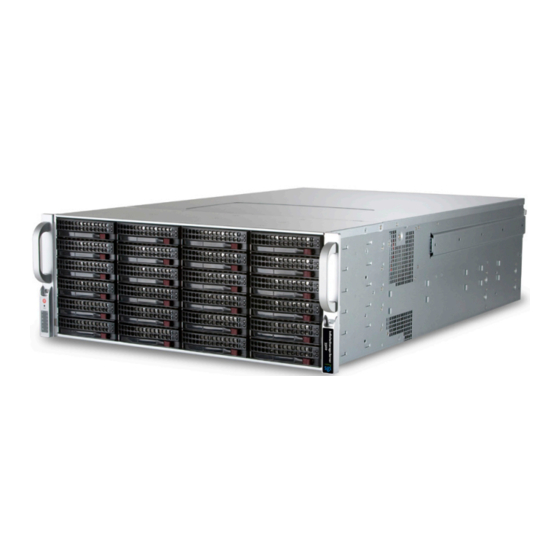
Figure 1-1 ISS3500 Server Front Panel Important: SGI systems may sometimes require driver versions that are not included in the original operating system release. SGI provides these required drivers on a special CD. For more information, see Appendix B, “System Drivers”. - Page 22 1: Introduction and System Components Overview The ISS3500 server has the following configuration options: • One or two 64-bit Intel Xeon processor 5600 series (Westmere-EP) processors • 4 to 12 memory DDR3 DIMMs • Four low-profile PCIe x8 Gen 2.0 slots (Slots 4– 7) •...
-
Page 23: Figure 1-2 Iss3500 Serverboard Block Diagram
#0-6 #1-6 #1-5 #0-5 #1-4 #0-4 #1-3 #0-3 #1-2 #0-2 #1-1 #0-1 Processor #2 Processor #1 PCI-E X8 Ports #7-8 Intel 5520 PCI-E X8 Ports IOH-36D #5-6 PCI-E X4 Ports #1-2 Ports PCI-E X8 #3-4 Ports PCI-E X8 Port #9-10 Ports LSI 2008 #0~3... -
Page 24: Racks
1: Introduction and System Components Overview Racks The following rack assemblies are available: • Short rack The 20U-high deskside rack holds a maximum of five 4U-high enclosures. • 39U tall rack The 39U-high rack holds a maximum of nine 4U-high enclosures. •... -
Page 25: Mounting Rails
QuickPath Interconnect Mounting Rails The ISS3500 system is shipped with mounting rails. See Chapter 3, “Installing the ISS3500 System in a Rack.”, to set up your rack. Power Supply Each ISS3500 system includes two redundant high-efficiency hot-swappable power supplies rated at 1400 Watts. -
Page 26: Pci Subsystem
1: Introduction and System Components Overview PCI Subsystem The primary I/O buses for the server board is PCI Express. Disk RAID Support The ISS3500 supports both software and hardware RAID. Two SATA RAID HBAs are added to the configuration to support a maximum of 38 disk drives with RAID (2 internal and 36 external). RAID is defined as an array of multiple independent hard disk drives that provides high performance and fault tolerance. -
Page 27: Raid 0 (Striping)
Disk RAID Support RAID 0 (Striping) Disk striping allows the writing of data across multiple physical disks instead of just one physical disk. It involves partitioning each disk drive storage space into stripes that can vary in size from 8KB to 128KB. RAID 1 (Mirrored) Disk mirroring has two disks;... -
Page 28: Raid 60 (Striping With Dual Parity)
1: Introduction and System Components Overview RAID 60 (Striping with Dual Parity) RAID 60 employs RAID 0 striping across lower-level RAID 6 arrays. Dual parity allows two disks in a sub-array to fail without a loss of data. 007-5653-001... -
Page 29: System Safety
Chapter 2 System Safety This chapter describes basic safety precautions. Electrical Safety Precautions Basic electrical safety precautions should be followed to protect yourself from harm and the ISS3500 system from damage, as follows: • Be aware of the locations of the power on/off switch on the chassis as well as the room's emergency power-off switch, disconnection switch or electrical outlet. -
Page 30: General Safety Precautions
2: System Safety • Serverboard Battery Caution: There is a danger of explosion if the onboard battery is installed upside down, which will reverse its polarites (see Figure 2-1). This battery must be replaced only with the same or an equivalent type recommended by the manufacturer. Dispose of used batteries according to the manufacturer's instructions. -
Page 31: Esd Precautions
ESD Precautions ESD Precautions Caution: Electrostatic discharge (ESD) is generated by two objects with different electrical charges coming into contact with each other. An electrical discharge is created to neutralize this difference, which can damage electronic components and printed circuit boards. The following measures are generally sufficient to neutralize this difference before contact is made to protect your equipment from ESD: •... -
Page 33: Installing The Iss3500 System In A Rack
Chapter 3 Installing the ISS3500 System in a Rack This chapter provides a quick setup checklist to get the ISS3500 operational. Unpack the System Inspect the shipping container that the ISS3500 was shipped in and note if it was damaged in any way. -
Page 34: Warnings And Precautions
3: Installing the ISS3500 System in a Rack Warnings and Precautions Rack Precautions Warning: The ISS3500 server weighs 80 lbs (36.3 kg). Always use proper lifting techniques when your move the server. Always get the assistance of another qualified person when you install the sever in a location above your shoulders. -
Page 35: Server Precautions
Rack Mounting Considerations Server Precautions • Review the electrical and general safety precautions. • Determine the placement of each component in the rack before you install the rails. • Install the heaviest server components in the bottom of the rack first, and then work up. •... -
Page 36: Circuit Overloading
3: Installing the ISS3500 System in a Rack Circuit Overloading Consideration should be given to the connection of the equipment to the power supply circuitry and the effect that any possible overloading of circuits might have on overcurrent protection and power supply wiring. -
Page 37: Outer Rack Rails
Install the System into a Rack Rail Assembly Extending the Rails Quick- Release Tab Separating the Inner Rail Extension Figure 3-1 Separating and Installing the Rack Rails Outer Rack Rails Outer rails attach to the rack and hold the chassis in place. The outer rails for the chassis extend between 30 inches and 33 inches. -
Page 38: Install The Outer Rails To The Rack
3: Installing the ISS3500 System in a Rack the ends of the 2U quick attach rails. Figure 3-2 shows the rail adapter and the end of the quick attach rail. Figure 3-2 Square-to-round Hole Adapter for 2U Quick Attach Rails Figure 3-3 shows the adapter clipped onto the rail set. -
Page 39: Install The Inner Rail Extension
Install the System into a Rack Install the Inner Rail Extensions The ISS3500 chassis includes a set of inner rails in two sections: inner rails and inner rail extensions. The inner rails are pre-attached to the chassis and do not interfere with normal use of the chassis if you decide not to use a server rack. -
Page 40: Install The Server In A Rack
3: Installing the ISS3500 System in a Rack Install the Server in a Rack Warning: The ISS3500 server weighs 80 lbs (36.3 kg) Always use proper lifting techniques when your move the server. Always get the assistance of another qualified person when you install the server in a location above your shoulders. -
Page 41: Check The Node Board Setup
Check the Node Board Setup Check the Node Board Setup Use the following sections to open the top cover and check that each node board is properly installed and all the connections have been made. Removing the Chassis Cover Unplug the chassis from any power source. 2. -
Page 42: Check The Cpus (Processors)
3: Installing the ISS3500 System in a Rack Figure 3-6 Removing the Chassis Cover Check the CPUs (processors) You may have one or two processors installed into the serverboard. Each processor needs its own heatsink. Check the System Memory Your server system is shipped with system memory installed. Make sure all DIMMs are fully seated in their slots. -
Page 43: Install Expansion Pci Cards
Check the Node Board Setup Install Expansion PCI Cards You can install six expansion PCI cards in the system. Check all Cable Connections and Airflow Make sure all power and data cables are properly connected and not blocking the chassis airflow. Check the Drive Bay Setup Next, you should check to make sure the system disk drives and disk drive backplane have been properly installed and all connections have been made. -
Page 44: Check The Airflow
“Install the System into a Rack” on page 16), and connect the power cord from the power supply module into a power strip or power distribution unit (PDU). SGI also recommends that you use an uninterruptible power supply (UPS) source. 007-5653-001... -
Page 45: Chassis Setup And Maintenance
Chapter 4 Chassis Setup and Maintenance This chapter covers the steps required to install components and perform maintenance on the ISS35500 chassis. For component installation, follow the steps in the order given to eliminate the most common problems encountered. If some steps are unnecessary, skip ahead to the step that follows. -
Page 46: Static-Sensitive Device
4: Chassis Setup and Maintenance Static-Sensitive Device Electrostatic discharge (ESD) can damage electronic components. To prevent damage to any printed circuit boards (PCBs), it is important to handle them very carefully. The following measures are generally sufficient to protect your equipment from ESD damage. Precautions •... -
Page 47: Installing The Hard Drives
Installing the Hard Drives Installing the Hard Drives The ISS3500 supports the following disk storage configurations: • Standard configuration (ISS-BASE-3500) This configuration includes an SAS3041e-IR HBA card in slot 1. This HBA supports two internal SATA disk drives and RAID 0, 1, 1E, and JBOD. •... -
Page 48: Removing The Hard Drive Carriers From The Chassis
4: Chassis Setup and Maintenance The Intelligent Battery Backup Unit (IBBU) protects the integrity of the cached data on the megaRAID controller for up to 72 hours in the event of a complete AC power failure or a brief power outage. Note: Your operating system must have RAID support to enable the hot-plug capability of the drives. -
Page 49: Installing A Hard Drive Into The Hard Drive Carrier
Installing the Hard Drives Installing a Hard Drive into the Hard Drive Carrier To install a hard drive into the hard drive carrier, perform the following steps: Remove the two screws securing the dummy drive to the drive carrier (see Figure 4-2). -
Page 50: Figure 4-3 Installing A Drive Into A Hard Drive Carrier
4: Chassis Setup and Maintenance SAS/SATA hard drive Hard drive Use a hard, stable carrier surface when installing the hard drive Figure 4-3 Installing a Drive into a Hard Drive Carrier 007-5653-001... -
Page 51: Dimm Slot Population
DIMM Slot Population DIMM Slot Population This section describes how you populate the DIMM slots for one or two CPUs with the various DIMM types. Note: The ISS3500 has 12 240-pin DIMM slots that support up to 96 GB of DDR3 Registered ECC or up to 24 GB of Unbuffered ECC/Non ECC 1333 MHz/1066 MHz/800 MHz SDRAM modules. -
Page 52: Dimm Module Types And Optimal Configuration
4: Chassis Setup and Maintenance DIMM Module Types and Optimal Configuration For memory to work properly, install memory according to the specifications in Table 4-4 Table 4-5. Table 4-4 DIMM Slots and DIMM Types Ranks per DIMM (any DIMMs DIMM Type combination;... -
Page 53: Table 4-5 Possible System Memory Allocation And Availability
DIMM Slot Population Table 4-5 Possible System Memory Allocation and Availability Physical Memory Remaining (-Available) (4 GB Total System System Device Size Memory) Firmware Hub flash memory (System 1 MB 3.99 GB BIOS) Local APIC 4 KB 3.99 GB Area Reserved for the chipset 2 MB 3.99 GB I/O APIC (4 Kbytes) -
Page 54: Pci Expansion Slots
4: Chassis Setup and Maintenance PCI Expansion Slots The PCI slot bays are in the rear of the chassis. The PCI slots are located at the rear of the chassis on the far right side. The slots are numbered from right to left (1–7 with slot 2 empty). All of the slots support low-profile PCI cards. -
Page 55: Installing An Add-On Or Expansion Card
PCI Expansion Slots Installing an Add-On or Expansion Card To install add-on or expansion cards, perform the following steps: 2. Remove the chassis cover. 3. Locate the motherboard port aligned with the card slot you want to install, 4. Each slot is secured by one screw located on the top (inside) the chassis. Remove this screw. 5. -
Page 56: Chassis Maintenance
4: Chassis Setup and Maintenance Chassis Maintenance This section describes basic chassis maintenance. System Fans Seven hot-swappable, heavy-duty fans provide cooling for the chassis. These fans circulate air through the chassis as a means of lowering the internal temperature of the chassis (see Figure 4-5) The ISS3500 chassis fans are fully hot-swappable. -
Page 57: Replacing A System Fan
Chassis Maintenance Replacing a System Fan Figure 4-6 Replacing a Fan To replace a fan, perform the following steps: Open the chassis while the power is running to determine which fan has failed. Never run the server for an extended period of time with the chassis open. 2. -
Page 58: Checking The System Air Flow
4: Chassis Setup and Maintenance Checking the System Air Flow To check the ISS3500 system air flow, perform the following steps: Make sure there are no objects to obstruct airflow in and out of the server. 2. Do not operate the server without drives or drive trays in the drive bays. 3. -
Page 59: Replacing The Power Supply
Power Supply Replacing the Power Supply The power supply for the ISS3500 system is redundant and hot-swappable. If you have this option (an additional power supply), you can replace the power supply with the system powered up, otherwise, the system must be powered off to replace the power supply. To replace the power supply, perform the following steps: The ISS3500 system includes a redundant power supply (at least two power modules). -
Page 61: System Monitoring
Chapter 5 System Monitoring Overview Shown in Figure 5-1, the control panel is located on the left handle of the chassis front. There are several LEDs on the control panel as well as others on the SATA drive carriers (see “SATA Drive Carrier LEDs”... -
Page 62: Control Panel Buttons
5: System Monitoring Control Panel Buttons There are two buttons located on the front of the chassis: a reset button and a power on/off button. Use the reset button to reboot the system as shown in Figure 5-2. Figure 5-2 Sysem Reset Button Figure 5-3 shows the the main power button, which is used to apply or turn off the main system... -
Page 63: Control Panel Leds
Control Panel LEDs Control Panel LEDs The control panel located on the front of the chassis has six LEDs. These LEDs provide you with critical information related to different parts of the system. This section explains what each LED indicates when illuminated and any corrective action you may need to take. Power The green power LED indicates power is being supplied to the system's power supply units is shown in... -
Page 64: Nic1
5: System Monitoring NIC1 When flashing, the green NIC1 LED indicates network activity on the LAN1 port (see Figure 5-6). Figure 5-6 LAN1 Network Activity NIC1 LED NIC2 When flashing, the green NIC2 LED indicates network activity on the LAN2 port (see Figure 5-7). -
Page 65: Power Fail
SATA Drive Carrier LEDs Power Fail The red power fail LED indicates a power supply module has failed as shown in Figure 5-9. The second power supply module will take the load and keep the system running but the failed module will need to be replaced. -
Page 67: Bios
Chapter 6 BIOS This chapter describes the AMI BIOS Setup Utility for the ISS3500 serverboard. The AMI ROM BIOS is stored in a Flash EEPROM and can be easily updated. This chapter describes the basic navigation of the AMI BIOS Setup Utility setup screens. Starting BIOS Setup Utility To enter the AMI BIOS Setup Utility screens, press the <Delete>... -
Page 68: How To Change The Configuration Data
Do not upgrade the BIOS unless your system has a BIOS-related issue. Flashing the wrong BIOS can cause irreparable damage to the system. In no event shall SGI be liable for direct, indirect, special, incidental, or consequential damages arising from a BIOS update. -
Page 69: System Time/System Update
Main Setup Figure 6-1 System Overview Main BIOS Setup Screen System Time/System Update Use this option to change the system time and date. Highlight System Time or System. Date using the arrow keys. Key in new values through the keyboard and press <Enter>. Press the <Tab> key to move between fields. -
Page 70: Serverboard
6: BIOS Serverboard • BIOS Build Version: This item displays the BIOS revision used in your system. • BIOS Build Date: This item displays the date when this BIOS was completed. • AMI BIOS Core Version: This item displays the revision number of the AMI BIOS Core upon which your BIOS was built. -
Page 71: Advanced Setup Configurations
Advanced Setup Configurations Advanced Setup Configurations Use the arrow keys to select Boot Setup and hit <Enter> to access the submenu items shown in Figure 6-2. Figure 6-2 Advanced Settings Screen 007-5653-001... -
Page 72: Boot Features
6: BIOS Boot Features This section describes the Boot Features options. Quick Boot If Enabled, this option will skip certain tests during POST to reduce the time needed for system boot. The options are Enabled and Disabled. Note: The default option is highlighted in bold face throughout this chapter. Quiet Boot This option allows the bootup screen options to be modified between POST messages or the OEM logo. -
Page 73: Interrupt 19 Capture
Advanced Setup Configurations Interrupt 19 Capture Interrupt 19 is the software interrupt that handles the boot disk function. When this item is set to Enabled, the ROM BIOS of the host adaptors will "capture" Interrupt 19 at boot and allow the drives that are attached to these host adaptors to function as bootable disks. -
Page 74: Processor And Clock Options
6: BIOS Processor and Clock Options This submenu allows the user to configure the Processor and Clock settings. Ratio CMOS Setting This option allows the user to set the ratio between the CPU Core Clock and the FSB Frequency. Note: If an invalid ratio is entered, the AMI BIOS will restore the setting to the previous state. The default setting depends on the type of CPU installed on the motherboard. -
Page 75: Max Cpuid Value Limit (Available When Supported By The Cpu)
Advanced Setup Configurations Max CPUID Value Limit (Available when supported by the CPU) Sets the maximum CPUID Value. Select Disabled for Microsoft Windows XP. The options are Enabled and Disabled. Intel Virtualization Technology (Available when supported by the CPU) Select Enabled to use the feature of Virtualization Technology to allow one platform to run multiple operating systems and applications in independent partitions, creating multiple "virtual"... -
Page 76: Intel Turbomode Technology (Available When Intel Eist Technology Is Enabled)
6: BIOS Intel TurboMode Technology (Available when Intel EIST Technology is enabled) Select Enabled to use the Turbo Mode to boost system performance. The options are Enabled and Disabled. Intel C-STATE Tech If enabled, C-State is set by the system automatically to either C2, C3 or C4 state. The options are Disabled and Enabled. -
Page 77: Advanced Chipset Control
Advanced Setup Configurations Advanced Chipset Control The items included in the Advanced Settings submenu are listed below: CPU Bridge Configuration QPI Links Speed This feature selects QPI's data transfer speed. The options are Slow-mode, and Full Speed. QPI Frequency This selects the desired QPI frequency. The options are Auto, 4.800 GT, 5.866GT, 6.400 GT. QPI L0s and L1 This enables the QPI power state to low power. - Page 78 6: BIOS Demand Scrubbing A memory error-correction scheme where the Processor writes corrected data back into the memory block from where it was read by the Processor. The options are Enabled and Disabled. Patrol Scrubbing A memory error-correction scheme that works in the background looking for and correcting resident errors.
-
Page 79: North Bridge Configuration
Advanced Setup Configurations Altitude This feature defines how many meters above or below sea level the system is located. The options are Sea Level or Below, 1~300, 301~600, 601~900, 901~1200, 1201~1500, 1501~1800, 1801~2100, 2101~2400, 2401~2700, 2701~3000. DIMM Pitch This is the physical space between each DIMM module. Each step is in 1/1000 of an inch. The default is [400]. -
Page 80: Intel Vt-D
6: BIOS Intel VT-d Select Enabled to enable Intel's Virtualization Technology support for Direct I/O VT-d by reporting the I/O device assignments to VMM through the DMAR ACPI Tables. This feature offers fully-protected I/O resource sharing across the Intel platforms, providing the user with greater reliability, security and availability in networking and data sharing. -
Page 81: Ide And Sata Configuration
Advanced Setup Configurations IDE and SATA Configuration When this submenu is selected, the AMI BIOS automatically detects the presence of the IDE devices and displays the following items: SATA#1 Configuration Configure SATA#1 as Selects the drive type for SATA#1. The options: •... -
Page 82: Pci/Pnp Configuration
6: BIOS PCI/PnP Configuration Clear NVRAM This feature clears the NVRAM during system boot. The options are No and Yes. Plug & Play OS Selecting Yes allows the OS to configure Plug & Play devices. (This is not required for system boot if your system has an OS that supports Plug &... -
Page 83: Super Io Device Configuration
Advanced Setup Configurations Super IO Device Configuration Onboard Floppy Controller Select Enable to enable the onboard floppy controller. The options are Enabled and Disabled. Floppy A/Floppy B Selects the type of floppy drive connected to the sys- tem as specified. The options are Disabled, 360KB 5 1/4", 1.2MB 5 1/4", 720KB 3 1/2", 1.44MB 3 1/2"... -
Page 84: Remote Access Configuration
6: BIOS Remote Access Configuration Remote Access This allows the user to enable the Remote Access feature. The options are Disabled and Enabled. If Remote Access is set to Enabled, the following items will display: Serial Port Number This feature allows the user decide which serial port to be used for Console Redirection. The options are COM 1 and COM 2, and COM 3. -
Page 85: Hardware Health Monitor
Advanced Setup Configurations Terminal Type This feature allows the user to select the target terminal type for Console Redirection. The options are ANSI, VT100, and VT-UTF8. VT-UTF8 Combo Key Support A terminal keyboard definition that provides a way to send commands from a remote console. Available options are Enabled and Disabled. -
Page 86: Cpu Temperature/System Temperature
6: BIOS threshold temperature as predefined by the CPU manufacturer to give the CPU and system fans additional time needed for CPU and system cooling. In both the alarms above, please take immediate action as shown below. CPU Temperature/System Temperature This feature displays current temperature readings for the CPU and the system. -
Page 87: System Fan Monitor
Advanced Setup Configurations User intervention: No action is required. However, consider checking the CPU fans and the chassis ventilation for blockage. High – The processor is running hot. This is a ‘caution’ level since the CPU’s ‘Temperature Tolerance’ has been reached (or has been exceeded) and may activate an overheat alarm. User intervention: If the system buzzer and Overheat LED has activated, take action immediately by checking the system fans, chassis ventilation and room temperature to correct any problems. -
Page 88: Acpi Configuration
6: BIOS ACPI Configuration Use this feature to configure Advanced Configuration and Power Interface (ACPI) power management settings for your system. ACPI Version Features The options are ACPI v1.0, ACPI v2.0, and ACPI v3.0. Please refer to ACPI's website for further explanation: http://www.acpi.info/. -
Page 89: Ipmi Configuration
Advanced Setup Configurations IPMI Configuration Intelligent Platform Management Interface (IPMI) is a set of common interfaces that IT administrators can use to monitor system health and to manage the system as a whole. For more information on the IPMI specifications, please visit Intel's website at www.intel.com. Status of BMC Baseboard Management Controller (BMC) manages the interface between system management software and platform hardware. -
Page 90: Clear Bmc System Event Log
6: BIOS Clear BMC System Event Log Select OK and press the <Enter> key to clear the BMC system log. Select Cancel to keep the BMC System log. The options are OK and Cancel. Caution: Any cleared information is unrecoverable. Make absolutely sure that you no longer need any data stored in the log before clearing the BMC Event Log. -
Page 91: Ip Address
Advanced Setup Configurations network. A static IP address that is assigned to a device is retained until it is manually re-assigned a different address or re-configured to receive an IP address through a DHCP server, as just noted. The options are DHCP and Static. IP Address Displays the IP address of this computer. -
Page 92: Subnet Mask Configuration
6: BIOS Subnet Mask Configuration Subnet masks tell the network to which subnet this machine belongs. The value of each three-digit number separated by dots should not exceed 255. Parameter Selector Use this feature to select the parameter of your Subnet Masks configuration. Subnet Mask This item displays the current subnet mask setting for your IPMI connection. - Page 93 Security Settings Figure 6-3 Security Settings Screen Supervisor Password This feature indicates if a supervisor's password has been entered (installed). User Password This feature indicates if a user's password has been entered (installed). Change Supervisor Password Select this option and press <Enter> to access the submenu, and then enter the password. 007-5653-001...
- Page 94 6: BIOS User Access Level (Available when Supervisor Password is set as just described.) Use this feature to set the user’s access level: • Full Access—Grants full read and write access to the setup utility. • View Only—Allows access to the setup utility but grants no permission to change fields. •...
-
Page 95: Boot Configuration
Boot Configuration Boot Configuration Use this feature to configure boot settings (see Figure 6-4). Figure 6-4 Boot Settings Screen Boot Device Priority This feature allows you to specify the sequence of priority for the Boot Device. The settings are 1st boot device, 2nd boot device, 3rd boot device, 4th boot device, 5th boot device and Disabled. •... -
Page 96: Hard Disk Drives
6: BIOS Hard Disk Drives This feature allows you to specify the boot sequence from all available hard disk drives. The settings are Disabled and a list of all hard disk drives that have been detected (for example, 1st Drive, 2nd Drive, 3rd Drive, etc). •... -
Page 97: Exit Options
Exit Options Exit Options Select the Exit tab from the AMI BIOS Setup Utility screen to enter the Exit BIOS Setup screen. Figure 6-5. Figure 6-5 Exit Options Screen Save Changes and Exit When you have completed the system configuration changes, select this option to leave the BIOS Setup Utility and reboot the computer so that the new system configuration parameters can take effect. -
Page 98: Discard Changes And Exit
6: BIOS Discard Changes and Exit Select this option to quit the BIOS Setup without making any permanent changes to the system configuration and to reboot the computer. Select Discard Changes and Exit from the Exit menu and press <Enter>. Discard Changes Select this option and press <Enter>... -
Page 99: Troubleshooting
“Losing the System’s Setup Configuration” on page 80 • “Memory Errors” on page 81 If you need further assistance, SGI provides extensive product support. See “Product Support” on page xix Note: Always disconnect the power cord before installing, replacing, or otherwise changing hardware components. -
Page 100: No Power
7: Troubleshooting No Power Make sure that no short circuits between the motherboard and the chassis. 2. Make sure that all jumpers are set to their default positions. 3. Check that the 115V/230V switch on the power supply is properly set. 4. -
Page 101: Memory Errors
Memory Errors Memory Errors When a No_Memory_Beep_Code is issued by the system, check the following: Make sure that the DIMM modules are properly and fully installed. 2. Check if different speeds of DIMMs have been installed. Use the same RAM speed for all DIMMs in the system. -
Page 103: Bios Error Codes
Appendix A BIOS Error Codes During Power-On Self-Test (POST) routines, which are performed each time the system is powered on, errors may occur. Non-fatal errors are those which, in most cases, allow the system to continue the boot-up process. The error messages normally appear on the screen. Fatal errors are those which will not allow the system to continue the boot-up procedure. -
Page 105: System Drivers
This appendix describes how you can access such drivers via SGI, Novell, and Red Hat. The appendix also includes a note about using MegaRAID drivers on SGI InfiniteStorage servers. -
Page 106: Using Megaraid Drivers On Sgi Infinitestorage Servers
Using MegaRAID Drivers on SGI InfiniteStorage Servers To avoid I/O timeouts with certain workloads, the megaraid_sas driver needs to have the poll_mode_io variable set to 1. For Novell operating systems, the file /etc/modprobe.conf.local needs the following line added: options megaraid_sas poll_mode_io=1 This modification will be made on systems shipped from the factory, but if a system is installed or upgraded in the field, this change will have to be made after installation/upgrade.
Need help?
Do you have a question about the InfiniteStorage Server 3500 and is the answer not in the manual?
Questions and answers