Table of Contents
Advertisement
Quick Links
Advertisement
Table of Contents

Related Manuals for Sun Oracle Sun Server X4-2


Summary of Contents for Sun Oracle Sun Server X4-2
-
Page 1: Service Manual
Sun Server X4-2 Service Manual Part No.: E38041-07 May 2014... - Page 2 Copyright © 2013, 2014, Oracle and/or its affiliates. All rights reserved. This software and related documentation are provided under a license agreement containing restrictions on use and disclosure and are protected by intellectual property laws. Except as expressly permitted in your license agreement or allowed by law, you may not use, copy, reproduce, translate, broadcast, modify, license, transmit, distribute, exhibit, perform, publish, or display any part, in any form, or by any means.
-
Page 3: Table Of Contents
Contents Using This Documentation xi About the Sun Server X4-2 1 Product Description 1 About Controls and Connectors 2 Front Panel Controls and Indicators on a System With Eight 2.5-inch Drives 3 Front Panel Controls and Indicators on a System With Four 2.5-inch Drives... - Page 4 Power Down Server Gracefully Using the Power Button 36 ▼ Use the Power Button for Immediate Shutdown 36 ▼ Use the Oracle ILOM CLI for Immediate Shutdown 37 ▼ Use the Oracle ILOM Web Interface for Immediate Shutdown 38 Sun Server X4-2 Service Manual • May 2014...
- Page 5 ▼ Disconnect Cables From the Server 39 ▼ Extend the Server to the Maintenance Position 39 ▼ Remove the Server From the Rack 41 ▼ Take Antistatic Measures 42 ▼ Open the Server Fan Door 43 ▼ Remove the Server Top Cover 43 Servicing CRUs That Do Not Require Server Power-Off 45 Servicing Storage Drives (CRU) 45 Storage Drives Hot-Plug Conditions 46...
- Page 6 Servicing the Internal USB Flash Drives (CRU) 94 Servicing the Oracle System Assistant USB Flash Drive 94 ▼ Remove an Internal USB Flash Drive 95 ▼ Install an Internal USB Flash Drive 95 Servicing the Battery (CRU) 96 Sun Server X4-2 Service Manual • May 2014...
- Page 7 ▼ Remove the Battery 97 ▼ Install the Battery 98 Servicing FRUs FRU Locations 99 Servicing Processors (FRU) 100 Selecting the Correct Processor Removal/Replacement Tool 102 ▼ Remove a Processor 106 ▼ Install a Processor 112 Servicing the Disk Backplane (FRU) 117 Disk Backplane Configurations 118 ▼...
- Page 8 Legacy Option ROM Allocation 170 I/O Resource Allocation 171 Common BIOS Setup Utility Tasks 172 ▼ Verify BIOS Factory Default Settings 172 ▼ Select Legacy BIOS or UEFI BIOS Boot Mode 173 viii Sun Server X4-2 Service Manual • May 2014...
- Page 9 ▼ Select the Boot Device 175 ▼ Configure iSCSI Virtual Drives 176 ▼ Enable or Disable Oracle System Assistant 184 ▼ Configure TPM Support 186 ▼ Configure SP Network Settings 189 ▼ Configure Option ROM Settings 192 ▼ Configure I/O Resource Allocation 193 ▼...
- Page 10 Identifying SNMP Trap Messages 239 Generic Host Events 240 Environmental Events 240 Hard Disk Drive Events 242 Power Events 243 Fan Events 246 Memory Events 248 Entity Presence Events 253 Physical Presence Events 254 Index 257 Sun Server X4-2 Service Manual • May 2014...
-
Page 11: Using This Documentation
Using This Documentation This service manual explains how to remove and replace parts in the Sun Server X4-2, and how to troubleshoot and maintain the system. This document is intended for system administrators, network administrators, and service technicians who have an understanding of server systems. This section describes how to get the latest software and firmware, documentation and feedback, and support and accessibility information. -
Page 12: About This Documentation
Oracle X4 Series Servers http://www.oracle.com/goto/x86AdminDiag/docs Administration Guide Oracle Integrated Lights Out http://www.oracle.com/goto/ILOM/docs Manager (ILOM) 3.1 Oracle Hardware http://www.oracle.com/goto/OHMP/docs Management Pack 2.2 Feedback You can provide feedback on this documentation at: http://www.oracle.com/goto/docfeedback Sun Server X4-2 Service Manual • May 2014... -
Page 13: Access To Oracle Support
Access to Oracle Support Oracle customers have access to electronic support through My Oracle Support. For information, visit http://www.oracle.com/pls/topic/lookup?ctx=acc&id= or visit info http://www.oracle.com/pls/topic/lookup?ctx=acc&id=trs if you are hearing impaired. Using This Documentation xiii... - Page 14 Sun Server X4-2 Service Manual • May 2014...
-
Page 15: About The Sun Server X4-2
Learn about system components. “About System Components” on page 15 Product Description The Sun Server X4-2 is an enterprise-class, one rack unit (1U) server. It supports the following components: Up to two Intel processors. Processors with the following capabilities are ■... -
Page 16: About Controls And Connectors
“Server Back Panel View” on page 5 ■ Related Information “About Server and Component Status Indicators” on page 6 ■ “About System Components” on page 15 ■ “Illustrated Parts Breakdown” on page 15 ■ Sun Server X4-2 Service Manual • May 2014... -
Page 17: Front Panel Controls And Indicators On A System With Eight 2.5-Inch Drives
With Eight 2.5-inch Drives The following figure shows the controls, status indicators (LEDs), connectors, and drives on the front panel of a Sun Server X4-2 configured with eight 2.5-inch storage drives. Front Panel View of a Server With Eight 2.5-inch Drives... -
Page 18: Front Panel Controls And Indicators On A System With Four 2.5-Inch Drives And Dvd Drive
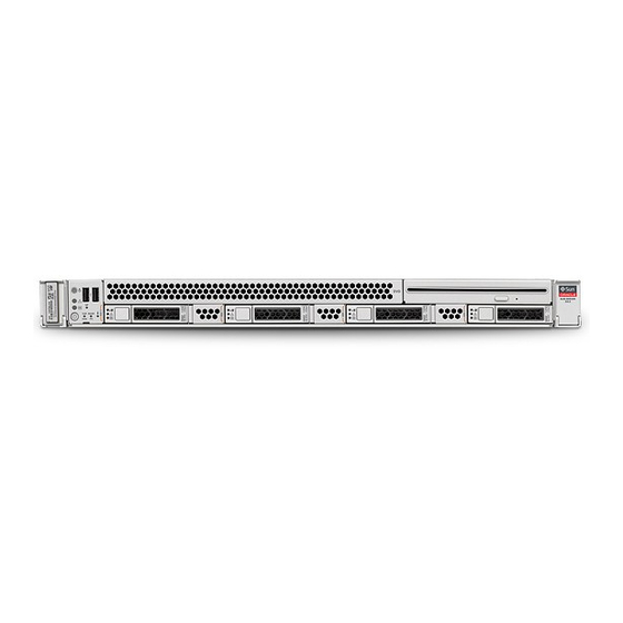
With Four 2.5-inch Drives and DVD Drive The following figure shows the controls, status indicators (LEDs), connectors, and drives on the front panel of a Sun Server X4-2 configured with four 2.5-inch storage drives and a SATA DVD drive. Front Panel View of a Server With Four 2.5-inch Drives and SATA DVD Drive... -
Page 19: Server Back Panel View
“Server Back Panel View” on page 5 ■ Server Back Panel View The following figure shows the Sun Server X4-2 back panel and the location of power supplies, status indicators (LEDs), connectors, and PCIe slots. Server Back Panel View FIGURE:... -
Page 20: About Server And Component Status Indicators
“Server General Status Indicators” on page 7 ■ “Server Fan Status Indicators” on page 9 ■ “Storage Drive Status Indicators” on page 10 ■ Sun Server X4-2 Service Manual • May 2014... -
Page 21: Server General Status Indicators
“Service Troubleshooting Task List” on page 21 ■ Server General Status Indicators There are seven, system-level status indicators (LEDs), some of which are located on both the server front panel and the server back panel. About the Sun Server X4-2... - Page 22 OS. SP OK Green • OFF – Service processor (SP) is not running. • SLOW BLINK – SP is booting. • STEADY ON – SP is fully operational. Sun Server X4-2 Service Manual • May 2014...
-
Page 23: Server Fan Status Indicators
• Amber – The fan module is faulty. The front TOP FAN LED and the Amber/Green front and rear panel Service Required LEDs are also lit if the system detects a fan module fault. • Green – The fan module is correctly installed and operating within specification. About the Sun Server X4-2... -
Page 24: Storage Drive Status Indicators
“Front Panel Controls and Indicators on a System With Four 2.5-inch Drives and ■ DVD Drive” on page 4 “Server Back Panel View” on page 5 ■ “Servicing Storage Drives (CRU)” on page 45 ■ Sun Server X4-2 Service Manual • May 2014... -
Page 25: Power Supply Status Indicators
Network Management Port Status Indicators The server has one 10/100BASE-T Ethernet management domain interface, labeled NET MGT. There are two status indicators (LEDs) on this port. These indicators are visible from the rear of the server. About the Sun Server X4-2... -
Page 26: Ethernet Ports Status Indicators
The server has four Ethernet ports (NET 3, NET 2, NET 1, and NET 0). There are two status indicators on each port. These indicators are visible from the rear of the server. Note – Ethernet ports NET 2 and NET 3 are nonfunctional in single-processor systems. Sun Server X4-2 Service Manual • May 2014... -
Page 27: Motherboard Status Indicators
(LED) associated with it. If Oracle ILOM determines that a DIMM is faulty, pressing the Fault Remind button on the motherboard signals the service processor to light the fault LEDs associated with the faulted DIMMs. About the Sun Server X4-2... -
Page 28: Processor Fault Status Indicators
“Front Panel Controls and Indicators on a System With Four 2.5-inch Drives and ■ DVD Drive” on page 4 “Server Back Panel View” on page 5 ■ “Illustrated Parts Breakdown” on page 15 ■ Sun Server X4-2 Service Manual • May 2014... -
Page 29: About System Components
“Servicing CRUs That Do Not Require Server Power-Off” on page 45 ■ “Servicing CRUs That Require Server Power-Off” on page 61 ■ “Servicing FRUs” on page 99 ■ Illustrated Parts Breakdown The following figure identifies the major components of the server. About the Sun Server X4-2... - Page 30 1 (P1). Server chassis for four 2.5-inch storage Battery drives and DVD drive SATA DVD drive PCIe cards and the internal HBA card Note: PCIe slot 1 is nonfunctional in single-processor systems. Sun Server X4-2 Service Manual • May 2014...
-
Page 31: Customer-Replaceable Units
2.5-inch storage drives Note - In Oracle Engineered Systems, storage drive 7 in eight-drive systems might be populated with a remote battery module for the HBA card. The battery module is not a customer-replaceable unit. About the Sun Server X4-2... -
Page 32: Field-Replaceable Units
Internal HBA Serve to connect the disk backplane to the “Servicing the SAS Cables (FRUs)” on SAS controller the internal host bus adapter (HBA) card. page 138 cables Sun Server X4-2 Service Manual • May 2014... -
Page 33: Battery Module
SG-SAS6-R-INT-Z. It enables Oracle field service personnel to replace the battery at the end of its service life without requiring the server to be powered off. Related Information “Servicing Storage Drives (CRU)” on page 45 ■ About the Sun Server X4-2... - Page 34 Sun Server X4-2 Service Manual • May 2014...
-
Page 35: Troubleshooting The Server
Inspect the system methodically to locate a “Inspecting the System” on page 25 faulty component or components. Related Information “About the Sun Server X4-2” on page 1 ■ “Preparing for Service” on page 29 ■ “Returning the Server to Operation” on page 143 ■... -
Page 36: Diagnostic Tools
Oracle x86 Servers Diagnostics, Applications, and Utilities Guide for Servers With Oracle ILOM 3.1 http://www.oracle.com/goto/x86AdminD iag/docs Related Information “About the Sun Server X4-2” on page 1 ■ “Diagnostic Tools” on page 22 ■ Diagnostic Tools There are a variety of diagnostic tools, commands, and indicators you can use to monitor and troubleshoot the server: LEDs –... - Page 37 Oracle ILOM where it will be logged, and, depending on the fault, might cause one or more LEDs to light. Related Information “About the Sun Server X4-2” on page 1 ■ Oracle Solaris OS documentation set at: ■...
-
Page 38: Gather Service Information
4. Check for potential device conflicts before you add a new device. 5. Check for version dependencies, especially with third-party software. Related Information “Diagnostic Tools” on page 22 ■ “Locate the Server Serial Number” on page 25 ■ Sun Server X4-2 Service Manual • May 2014... -
Page 39: Locate The Server Serial Number
“Troubleshoot Power Problems” on page 26 ■ “Inspect the Server Externally” on page 26 ■ “Inspect Internal Server Components” on page 26 ■ Related Information “About the Sun Server X4-2” on page 1 ■ “Preparing for Service” on page 29 ■ Troubleshooting the Server... -
Page 40: Troubleshoot Power Problems
3. If the problem is not evident, continue with the next section, “Inspect Internal Server Components” on page Related Information “About the Sun Server X4-2” on page 1 ■ “Inspect Internal Server Components” on page 26 ■ ▼ Inspect Internal Server Components 1. - Page 41 2. Disconnect the AC power cables from the server, extend the server to the maintenance position, and remove the server top cover. “Preparing the Server for Component Replacement” on page 3. Inspect the internal status indicators (LEDs), which can indicate component malfunction.
- Page 42 “Returning the Server to Operation” on page 143 ■ Sun Server X4-2 Service Manual • May 2014...
-
Page 43: Preparing For Service
Follow all standard cautions, warnings, and instructions marked on the ■ equipment and described in the online Sun Server X4-2 Safety and Compliance Guide and in the printed Important Safety Information for Oracle’s Hardware Systems. Ensure that the voltage and frequency of your power source match the voltage ■... -
Page 44: Fru Tli Auto-Update
The following symbols might appear in this book. Note their meanings. Caution – There is a risk of personal injury or equipment damage. To avoid personal injury or equipment damage, follow the instructions. Sun Server X4-2 Service Manual • May 2014... -
Page 45: Electrostatic Discharge Safety
Caution – The surface of the component is hot. Avoid contact. Surfaces are hot and might cause personal injury if touched. Caution – Hazardous voltages are present. To reduce the risk of electric shock and danger to personal health, follow the instructions. Related Information “Safety Precautions”... -
Page 46: Required Tools
“Preparing for Service” on page 29 ■ “Servicing CRUs That Do Not Require Server Power-Off” on page 45 ■ “Servicing CRUs That Require Server Power-Off” on page 61 ■ “Servicing FRUs” on page 99 ■ Sun Server X4-2 Service Manual • May 2014... -
Page 47: Preparing The Server For Component Replacement
Preparing the Server for Component Replacement Before you can remove and install components that are inside the server, you must perform the procedures in the following tasks: Note – When replacing the storage drives or power supplies, not all of these procedures are necessary. -
Page 48: Power Down Server Gracefully Using The Oracle Ilom Cli
4. Log in to the Oracle ILOM command-line interface (CLI) using an Administrator account. For instructions, see the Sun Server X4-2 Installation Guide, “Log In to Oracle ILOM Remotely Using the CLI” on page 5. At the Oracle ILOM prompt, shut down the operating system: ->... -
Page 49: Power Down Server Gracefully Using The Oracle Ilom Web Interface
4. Log in to the Oracle ILOM web interface using an Administrator account. For instructions, see the Sun Server X4-2 Installation Guide, “Log In to Oracle ILOM Remotely Using the Web Interface” on page The Oracle ILOM web interface System Information > Summary page appears. -
Page 50: Power Down Server Gracefully Using The Power Button
▼ Use the Power Button for Immediate Shutdown Caution – You might corrupt your system data during an immediate power down, so only use this procedure to power down the server after attempting the graceful power down procedure. Sun Server X4-2 Service Manual • May 2014... -
Page 51: Use The Oracle Ilom Cli For Immediate Shutdown
1. Press and hold the Power button for four seconds to force the main power off and to enter standby power mode. When main power is off, the Power/OK LED on the front panel will begin flashing, indicating that the server is in standby power mode. See “Server General Status Indicators”... -
Page 52: Use The Oracle Ilom Web Interface For Immediate Shutdown
Related Information “Use the Power Button for Immediate Shutdown” on page 36 ■ “Power Down Server Gracefully Using the Oracle ILOM CLI” on page 34 ■ Sun Server X4-2 Service Manual • May 2014... -
Page 53: Disconnect Cables From The Server
▼ Disconnect Cables From the Server Caution – The system supplies standby power to the circuit boards when the power cords are connected even when the system is powered off. 1. Label all cables connected to the server. 2. Disconnect the power cords from the rear of the server. 3. - Page 54 Note – The slide-rail locks are located behind the flip-down handles on the front of the server. The slide-rail locks are released when the flip-down handles are pulled down. The server is now in the extended maintenance position. Sun Server X4-2 Service Manual • May 2014...
-
Page 55: Remove The Server From The Rack
Slide-Rail Release Latches FIGURE: Figure Legend Slide-rail lock Slide-rail release tab 4. Slowly pull the server out of the rack until the slide-rails latch. Related Information “Disconnect Cables From the Server” on page 39 ■ “Remove the Server From the Rack” on page 41 ■... -
Page 56: Take Antistatic Measures
2. Attach an antistatic wrist strap. When servicing or removing server components, attach an antistatic strap to your wrist and then to a metal area on the chassis. Then disconnect the power cords from the server. Sun Server X4-2 Service Manual • May 2014... -
Page 57: Open The Server Fan Door
Note – An antistatic wrist strap is not included in the Ship Kit for the server. However, antistatic wrist straps are still included with options and components. Related Information “Remove Antistatic Measures” on page 146 ■ ▼ Open the Server Fan Door Servicing the server fan modules and other components located in the front of the server, such as the front indication module, the DVD drive, and disk backplanes, requires that the fan door be opened. - Page 58 Removing the Server Top Cover FIGURE: 4. Lift the cover off the chassis and set it aside [2]. Related Information “Take Antistatic Measures” on page 42 ■ “Install the Server Top Cover” on page 145 ■ Sun Server X4-2 Service Manual • May 2014...
-
Page 59: Servicing Crus That Do Not Require Server Power-Off
These sections describe how to remove and install storage drives: In addition to the service procedures included here, you can see animations that show how to remove and install the storage drives. To play the Sun Server X4-2 Service Animations go to: http://docs.oracle.com/cd/E36975_01/html/E49470/index.html See the following procedures:... -
Page 60: Storage Drives Hot-Plug Conditions
A single storage drive failure does not cause a data failure if the storage drives are configured as a mirrored RAID 1 volume (optional). The storage drive can be removed, and when a new storage drive is inserted, the contents are automatically Sun Server X4-2 Service Manual • May 2014... -
Page 61: Storage Drive Status Indicators
For instructions for configuring RAID on the server, refer to the Sun Server X4-2 Installation Guide, “Configuring Server Drives for OS Installation” on page 113. - Page 62 Note – The blue OK to Remove LED on the storage drive might not light, as support for this varies depending on the operating system in use. The exact commands required depend on the configuration of your drives. Unmount file systems or issue RAID commands as needed. Sun Server X4-2 Service Manual • May 2014...
-
Page 63: Install A Storage Drive
4. On the drive you plan to remove, push the latch release button to open the drive latch. Locating the Hard Disk Drive Release Button and Latch FIGURE: Caution – The latch is not an ejector. Do not open the latch too far to the right. Doing so can damage the latch. -
Page 64: Servicing Fan Modules (Cru)
“HDD or SSD Failure and RAID” on page 46 ■ “Remove a Storage Drive” on page 47 ■ Servicing Fan Modules (CRU) The fan modules are located in the front of the server. Sun Server X4-2 Service Manual • May 2014... -
Page 65: Remove A Fan Module
In addition to the service procedures included here, you can see animations that show how to remove and install the fans. To play the Sun Server X4-2 Service Animations go to: http://docs.oracle.com/cd/E36975_01/html/E49470/index.html See the following procedures: “Remove a Fan Module” on page 51 ■... - Page 66 Using your thumb and forefinger, grasp the fan module in the finger recesses located in the plastic between the fans. b. Lift the fan module straight up and out of the chassis. Sun Server X4-2 Service Manual • May 2014...
- Page 67 Caution – When removing a fan module, do not rock it back and forth. Rocking the fans module can cause damage to the motherboard connectors. Removing a Fan Module FIGURE: 5. Set the fan module aside. Caution – Do not service any other components in the fan compartment unless the system is shut down and the power cords are removed.
-
Page 68: Install A Fan Module
“About Server and Component Status Indicators” on page 6 for more information about identifying and interpreting system indicators. 7. Consider your next step: If you installed the fan module as part of another procedure, return to that ■ procedure. Sun Server X4-2 Service Manual • May 2014... -
Page 69: Servicing Power Supplies (Cru)
Otherwise, return the server to operation. ■ “Returning the Server to Operation” on page 143. Related Information “Remove a Fan Module” on page 51 ■ Servicing Power Supplies (CRU) The redundant power supplies on the server support concurrent maintenance, which enables you to remove and replace a power supply without shutting down the server, provided that the other power supply is online and working. -
Page 70: Power Supply Status Indicators
To play the Sun Server X4-2 Service Animations go to: http://docs.oracle.com/cd/E36975_01/html/E49470/index.html See the following sections for more information: “Power Supply Status Indicators” on page 56 ■ “Remove a Power Supply” on page 57 ■ “Install a Power Supply” on page 59 ■... -
Page 71: Remove A Power Supply
For instructions for disconnecting the CMA left-side connectors, see the Sun Server X4-2 Installation Guide, “Remove the Second-Generation Cable Management Arm” on page 64 Sun Server X4-2 Installation Guide, “Install the First-Generation Cable Management Arm” on page 69 as applicable. Servicing CRUs That Do Not Require Server Power-Off... - Page 72 “Install a Power Supply” on page Related Information “Server Back Panel View” on page 5 ■ “Power Supply Status Indicators” on page 56 ■ “Install a Power Supply” on page 59 ■ Sun Server X4-2 Service Manual • May 2014...
-
Page 73: Install A Power Supply
For instructions for reconnecting the CMA left-side connectors, see Sun Server X4-2 Installation Guide, “Install the Second-Generation Cable Management Arm” on page 52 Sun Server X4-2 Installation Guide, “Install the First-Generation Cable Management Arm” on page 69 as applicable. Servicing CRUs That Do Not Require Server Power-Off... - Page 74 Related Information “Server Back Panel View” on page 5 ■ “Power Supply Status Indicators” on page 56 ■ “Remove a Power Supply” on page 57 ■ Sun Server X4-2 Service Manual • May 2014...
-
Page 75: Servicing Crus That Require Server Power-Off
Servicing CRUs That Require Server Power-Off These sections describe how to service customer-replaceable units (CRUs) that require you to power off the server. Description Learn about the locations of the CRUs. “CRU Locations” on page 61 Service the DIMMs. “Servicing the DIMMs (CRU)” on page 62 Service the PCIe Risers. -
Page 76: Servicing The Dimms (Cru)
PCIe riser for slot 1 (CRU) (nonfunctional in single-processor systems) PCIe riser for slots 3 and 4 (CRU) USB flash drives (CRU) Servicing the DIMMs (CRU) This section describes how to remove and install DIMMs. Sun Server X4-2 Service Manual • May 2014... - Page 77 The Sun Server X4-2 supports a variety of DDR3 DIMM configurations that can include quad-rank (QR), dual-rank (DR), and single-rank (SR) DDR3 DIMMs. Note – While single-rank DIMMs can be installed in the Sun Server X4-2, Oracle does not offer any single-rank DIMMs for purchase, either as factory-installed options or as separately orderable options.
-
Page 78: Dimm And Processor Physical Layout
DIMM and Processor Physical Layout FIGURE: Note – In single-processor systems, the DIMM sockets associated with the processor 1 (P1) socket are nonfunctional and should not be populated with DIMMs or DIMM filler panels. Sun Server X4-2 Service Manual • May 2014... -
Page 79: Dimm Population Example For Optimal System Performance
Related Information “DIMM Population Example for Optimal System Performance” on page 65 ■ “DIMM Population Rules” on page 67 ■ “DIMM Rank Classification Labels” on page 69 ■ “Inconsistencies Between DIMM Fault Indicators and the BIOS Isolation of Faulty ■ DIMMs”... -
Page 80: Dimm Population Order For Single-Processor Systems
The following table describes the order in which the DIMM sockets should be populated in dual-processor systems. The figure callouts in columns two and four of the table refer to callouts in FIGURE: DIMM Population Order on page Sun Server X4-2 Service Manual • May 2014... -
Page 81: Dimm Population Rules
DIMM Population Order for Dual-Processor Systems TABLE: Population DIMM Sockets for DIMM Sockets for Order Figure Callouts Processor 0 (P0) Figure Callouts Processor 1 (P1) Fill the blue sockets first First Fill D0 first Then D0 Second Fill D2 first Then D2 Third Fill D5 first... - Page 82 Maximum memory frequency supported by processor ■ Maximum memory frequency supported by the installed DIMMs ■ Memory configuration within a channel ■ Sun Server X4-2 Service Manual • May 2014...
-
Page 83: Dimm Rank Classification Labels
2Rx4 Single-rank DIMM 1Rx4 Note – While single-rank DIMMs can be installed in the Sun Server X4-2, Oracle does not offer any single-rank DIMMs for purchase, either as factory-installed options or as separately orderable options. Servicing CRUs That Require Server Power-Off... -
Page 84: Inconsistencies Between Dimm Fault Indicators And The Bios Isolation Of Faulty Dimms
LEDs lit or if power has been removed from the server for more than 15 minutes. The following figure shows the location of the Fault Remind button. Sun Server X4-2 Service Manual • May 2014... -
Page 85: Identify And Remove A Faulty Dimm
Fault Remind Button Location FIGURE: ▼ Identify and Remove a Faulty DIMM 1. Prepare the server for service. a. Power off the server, and disconnect the power cords from the power supplies. “Powering Down the Server” on page 33 b. Extend the server to the maintenance position. “Extend the Server to the Maintenance Position”... - Page 86 (quad rank, dual rank, or single rank) or leave the socket empty. Note – DIMM filler panels are optional and not required. For DIMM replacement instructions, see “Install a DIMM” on page Sun Server X4-2 Service Manual • May 2014...
-
Page 87: Install A Dimm
DIMM Socket Release and Alignment FIGURE: Figure Legend DIMM connector socket DIMM connector key DIMM ejector lever ▼ Install a DIMM 1. Unpack the replacement DDR3 DIMM and place it on an antistatic mat. 2. Ensure that the replacement DDR3 DIMM matches the size of the DIMM it is replacing. -
Page 88: Servicing Pcie Risers (Cru)
This section describes how to remove and install the PCIe risers. In addition to the service procedures included here, you can see animations that show how to remove and install the PCIe risers. Sun Server X4-2 Service Manual • May 2014... -
Page 89: Pcie Riser Location And Differences
To play the Sun Server X4-2 Service Animations go to: http://docs.oracle.com/cd/E36975_01/html/E49470/index.html PCIe cards in all slots are installed on vertical risers. You must remove the relevant riser to remove and replace a PCIe card. You must remove all three PCIe risers when replacing the motherboard. -
Page 90: Remove A Pcie Riser From Pcie Slot 1
Note: This riser is different from the risers in slots 1 and 2. Related Information “PCIe Slot Characteristics” on page 85 ■ ▼ Remove a PCIe Riser From PCIe Slot 1 or 2 Note – PCIe slot 1 is nonfunctional in single-processor systems. Sun Server X4-2 Service Manual • May 2014... - Page 91 1. Prepare the server for service. a. Power off the server and disconnect the power cords from the power supplies. “Powering Down the Server” on page b. Extend the server to the maintenance position. “Extend the Server to the Maintenance Position” on page c.
-
Page 92: Install A Pcie Riser Into Pcie Slot 1
3. Raise the green-tabbed release lever on the PCIe riser to the open (up) position [1]. 4. Gently press the riser into the motherboard connector until it is seated, and then press the green-tabbed release lever on the PCIe riser to the closed (down) position [2]. Sun Server X4-2 Service Manual • May 2014... - Page 93 5. If there is a PCIe card installed in the riser, reconnect any external or internal cables to the card. 6. Close the green-tabbed latch on the rear of the server chassis next to the applicable PCIe slot to secure the rear bracket on the PCIe card to the server chassis [3].
-
Page 94: Remove A Pcie Riser From Pcie Slots 3 And 4
3. Open the green-tabbed latch located on the rear of the server chassis next to PCIe slot 3 to release the rear bracket on the PCIe card [1]. Sun Server X4-2 Service Manual • May 2014... - Page 95 Note – If the riser does not have a PCIe card installed in slot 3, then lift the latch to release the PCIe slot 3 filler panel. 4. To release the riser from the motherboard connector, lift the green-tabbed lease lever on the PCIe riser to the open position [2].
-
Page 96: Install A Pcie Riser Into Pcie Slots 3 And 4
3. Raise the green-tabbed release lever on the PCIe riser to the open (up) position, and then gently press the riser into the motherboard connector until it is seated [2]. Sun Server X4-2 Service Manual • May 2014... - Page 97 4. Ensure that the rear bracket on the internal HBA card in PCIe slot 4 is connected to the slot in the server chassis side wall. If the bracket is not connected, remove the riser and reposition it so that the rear bracket connects to the side wall, and then gently press the riser into the motherboard connector.
-
Page 98: Servicing Pcie Cards (Cru)
PCIe cards. You must disconnect all power cables from the system before performing these procedures. Note – For a complete list of supported PCIe cards, see the Sun Server X4-2 Product Notes at http://www.oracle.com/goto/X4-2/docs. The following sections provide information to assist you when servicing PCIe cards: “PCIe Slot Characteristics”... -
Page 99: Pcie Slot Characteristics
■ PCIe Slot Characteristics There are three external and one internal PCIe slots available in the Sun Server X4-2. The external slots support optional, standard PCIe cards and are numbered 1, 2, and 3 from left to right when you view the server from the rear. The internal slot, which installs on the riser in PCIe slots 3 and 4, supports a required internal SAS controller HBA card. -
Page 100: Remove A Pcie Card From Pcie Slot 1
PCIe card or a PCIe filler panel. Installing PCIe filler panels in vacant PCIe slots helps reduce the level of electromagnetic interference (EMI) emitted by the server. For instructions for installing a PCIe filler panel, see “Removing and Installing Server Filler Panels” on page 143. Sun Server X4-2 Service Manual • May 2014... -
Page 101: Install A Pcie Card In Pcie Slot 1
▼ Install a PCIe Card in PCIe Slot 1 or 2 Note – PCIe slot 1 is nonfunctional in single-processor systems. 1. Retrieve the PCIe card and riser you to install. 2. Insert the rear bracket that is attached to the PCIe card into the PCIe riser. 3. -
Page 102: Install A Pcie Card In Pcie Slot 3
2. Insert the rear bracket that is attached to the PCIe card into the PCIe riser. 3. Hold the riser in one hand and use your other hand to carefully insert the PCIe card connector into the riser. Sun Server X4-2 Service Manual • May 2014... -
Page 103: Remove The Internal Hba Card From Pcie Slot 4
4. Install the PCIe riser. For instructions, see “Install a PCIe Riser Into PCIe Slots 3 and 4” on page ▼ Remove the Internal HBA Card From PCIe Slot 4 1. Remove the PCIe riser from slots 3 and 4. For instructions, see “Remove a PCIe Riser From PCIe Slots 3 and 4”... -
Page 104: Install The Internal Hba Card In Pcie Slot 4
2. Insert the rear bracket that is attached to the internal HBA card into the rear connector on the PCIe riser. 3. Insert the internal HBA card connector into the bottom connector on the riser. Sun Server X4-2 Service Manual • May 2014... -
Page 105: Servicing The Dvd Drive (Cru)
4. Install the PCIe riser. For instructions, see “Install a PCIe Riser Into PCIe Slots 3 and 4” on page Servicing the DVD Drive (CRU) Note – The DVD drive is only available in the four-drive systems. The DVD drive is accessible from the front panel of the system. Caution –... - Page 106 Remove the server top cover. “Remove the Server Top Cover” on page 3. Locate the DVD drive [1]. 4. Disconnect the cable from the rear of the DVD [2]. Removing the DVD Drive FIGURE: Sun Server X4-2 Service Manual • May 2014...
-
Page 107: Install The Dvd Drive
5. To disengage the DVD drive from the chassis, press and hold the release tab on the rear of the DVD drive up slightly [3]. 6. Gently push the DVD drive toward the front of the server, slide it out of the server, and place it on an antistatic mat [4]. -
Page 108: Servicing The Internal Usb Flash Drives (Cru)
USB flash drive. For instructions for troubleshooting and repairing Oracle System Assistant, see the Oracle System Assistant troubleshooting information in the Oracle X4 Series Servers Administration Guide at http://www.oracle.com/goto/x86AdminDiag/docs. Sun Server X4-2 Service Manual • May 2014... -
Page 109: Remove An Internal Usb Flash Drive
▼ Remove an Internal USB Flash Drive The server can be equipped with up to two internal USB flash drives. Before you remove a the USB flash drive on which Oracle System Assistant is installed, review “Servicing the Oracle System Assistant USB Flash Drive” on page 94 1. -
Page 110: Servicing The Battery (Cru)
Caution – Ensure that all power is removed from the server before removing or installing the battery. You must disconnect the power cables from the system before performing these procedures. The following procedures are provided in this section: “Remove the Battery” on page 97 ■ Sun Server X4-2 Service Manual • May 2014... -
Page 111: Remove The Battery
“Install the Battery” on page 98 ■ Related Information “Extend the Server to the Maintenance Position” on page 39 ■ “Remove the Server Top Cover” on page 43 ■ ▼ Remove the Battery 1. Prepare the server for service. a. Power off the server and disconnect the power cords from the power supplies. -
Page 112: Install The Battery
“Power On the Server” on page 150. Verify that the Power/OK status indicator is steady on. Note – On first boot, use the BIOS Setup utility to reset the server host time. Sun Server X4-2 Service Manual • May 2014... -
Page 113: Servicing Frus
Servicing FRUs The following sections describe how to service field-replaceable units (FRUs). You must power down the system and disconnect the AC power cords from the server before servicing any of these components. Note – Only Oracle authorized service personnel should service FRUs. Description Link Identify FRU locations. -
Page 114: Servicing Processors (Fru)
Disk backplane (FRU) Note: In single-processor systems, the processor is installed in socket 0 (P0). Motherboard (FRU) Not applicable Servicing Processors (FRU) This section describes how to remove and install the processors. Sun Server X4-2 Service Manual • May 2014... - Page 115 In addition to the service procedures included here, you can see animations that show how to remove and install the processors. To play the Sun Server X4-2 Service Animations go to: http://docs.oracle.com/cd/E36975_01/html/E49470/index.html Caution – Ensure that all power is removed from the server before removing or installing a processor.
-
Page 116: Selecting The Correct Processor Removal/Replacement Tool
The processors supported by the Sun Server X4-2 come in two sizes. The processors with 10 or fewer cores are smaller than the processors with 12 cores. You can... - Page 117 Smaller Processor Installed in a Motherboard Processor Socket FIGURE: Figure Legend Processor alignment brackets Processor left and right edges are within alignment bracket boundaries FIGURE: Larger Processor Installed in a Motherboard Processor Socket on page 104 shows a larger processor installed. Notice that the right and left edges of the processor extend beyond the boundaries of the processor alignment brackets.
- Page 118 The tool for the smaller processors (processors with 10 or fewer cores) is color-coded green. The tool for the larger processors (12-core processors) is color-coded pink. See FIGURE: Color-Coded Processor Removal/Replacement Tools on page 105. Sun Server X4-2 Service Manual • May 2014...
- Page 119 Color-Coded Processor Removal/Replacement Tools FIGURE: Figure Legend Green, color-coded removal/replacement tool for the smaller processors—models E5-2609 V2 (4-core), E5-2630 V2 (6-core), E5-2650 V2 (8-core), and E5-2690 V2 (10-core) Pink, color-coded removal/replacement tool for the larger processor—model E5-2697 V2 (12-core) Caution – The pink color-coded processor removal/replacement tool must be used only with the larger processor (the 12-core processor).
-
Page 120: Remove A Processor
Always use the processor removal/replacement tool to remove and replace the processor. 1. Prepare the server for service. a. Power off the server and disconnect the power cords from the power supplies. “Powering Down the Server” on page Sun Server X4-2 Service Manual • May 2014... - Page 121 b. Extend the server to the maintenance position. “Extend the Server to the Maintenance Position” on page c. Attach an antistatic wrist strap to your wrist, and then to a metal area on the chassis. “Take Antistatic Measures” on page d.
- Page 122 Note – Do not allow the thermal grease to contaminate the work space or other components. 5. Use an alcohol pad to clean the thermal grease from the underside of the heatsink. Be careful not to get the thermal grease on your fingers. Sun Server X4-2 Service Manual • May 2014...
- Page 123 Caution – Failure to clean the heatsink prior to removing the processor could result in the accidental contamination of the processor socket or other components. Also, be careful not to get the grease on your fingers as this could result in contamination of components.
- Page 124 For information on how to select the correct processor removal/replacement tool, see “Selecting the Correct Processor Removal/Replacement Tool” on page 102. Sun Server X4-2 Service Manual • May 2014...
- Page 125 Removing a Processor FIGURE: Related Information “Install a Processor” on page 112 ■ Servicing FRUs...
-
Page 126: Install A Processor
Caution – Before installing the processor, ensure that you are using the correct color-coded processor removal/replacement tool. For information on how to select the correct processor removal/replacement tool, see “Selecting the Correct Processor Removal/Replacement Tool” on page 102. Sun Server X4-2 Service Manual • May 2014... - Page 127 a. Press the button in the center of the tool to the down position (see FIGURE: Installing a Processor on page 114 [1]). b. Turn the tool upside down, grasp the processor by its front an back edges and position the processor (circuit side up) in the tool so that the triangle on the corner of the processor aligns with the triangle on the side of the processor removal/replacement tool [2].
- Page 128 Caution – Do not press down on the processor. Irreparable damage to the processor or motherboard might occur from excessive downward pressure. Do not forcibly seat the processor into the socket. Excessive downward pressure might damage the socket pins. Sun Server X4-2 Service Manual • May 2014...
- Page 129 7. Swing the processor ILM assembly load plate into the closed position [1]. Ensure that the load plate sits flat around the periphery of the processor. 8. Engage the processor ILM assembly load lever on the left side of the socket (viewing the server from the front) by rotating it downward and slipping it under the catch [2].
- Page 130 Verify that the Power/OK status indicator is steady on. 16. Use Oracle ILOM to clear server processor faults. Refer to the Oracle Integrated Lights Out Manager (ILOM) 3.1 Documentation Library for more information about the following steps. Sun Server X4-2 Service Manual • May 2014...
-
Page 131: Servicing The Disk Backplane (Fru)
a. To show server faults, log in to the server as root using the Oracle ILOM CLI, and type the following command to list all known faults on the server: -> show /PS/faultmgmt The server lists all known faults, for example: ->... -
Page 132: Disk Backplane Configurations
To play the Sun Server X4-2 Service Animations go to: http://docs.oracle.com/cd/E36975_01/html/E49470/index.html Caution – Ensure that all power is removed from the server before removing or installing a disk backplane. You must disconnect the power cables from the server before performing these procedures. -
Page 133: Remove The Disk Backplane
Disk Backplane Configurations FIGURE: ▼ Remove the Disk Backplane Note – A server with four or fewer storage drives has only one disk backplane. 1. Prepare the server for service. a. Power off the server and disconnect the power cords from the power supplies. - Page 134 Sun Server X4-2 Service Manual • May 2014...
- Page 135 Removing the Disk Backplane FIGURE: 5. Disconnect the disk backplane power cable from the disk backplane [2]. 6. Disconnect the disk backplane LED cable from the disk backplane [3]. 7. If the server has a DVD drive, disconnect the DVD drive power cable from the disk backplane [4].
-
Page 136: Install The Disk Backplane
▼ Install the Disk Backplane 1. Starting with the bottom disk backplane if servicing a server with two disk backplanes, lower the backplane into the server and position it to engage the three mushroom-shaped standoffs [1]. Sun Server X4-2 Service Manual • May 2014... - Page 137 Installing the Disk Backplane FIGURE: 2. Using just your thumb and fingers, tighten the two captive thumb screws to secure the disk backplane to the chassis [2]. 3. If the server has a DVD drive, reconnect the DVD drive power cable to the disk backplane [3].
- Page 138 (SP). For instructions on resetting the SP, see the Oracle Integrated Lights Out Manager (ILOM) 3.1 Configuration and Maintenance Guide at http://www.oracle.com/goto/ILOM/docs Related Information “Remove the Disk Backplane” on page 119 ■ Sun Server X4-2 Service Manual • May 2014...
-
Page 139: Servicing The Front Indicator Module (Fru)
Servicing the Front Indicator Module (FRU) Caution – Ensure that all power is removed from the server before removing or installing a front indicator module. You must disconnect the power cables from the server before performing these procedures. Follow these procedures to remove and install the front indicator module (FIM). “Remove the Front Indicator Module”... - Page 140 5. Disconnect the FIM cable from the FIM assembly and set the assembly aside [3]. 6. Continue to “Install the Front Indicator Module” on page 127. Related Information “Install the Front Indicator Module” on page 127 ■ Sun Server X4-2 Service Manual • May 2014...
-
Page 141: Install The Front Indicator Module
▼ Install the Front Indicator Module 1. Attach an antistatic wrist strap to your wrist, and then to a metal area on the chassis. “Take Antistatic Measures” on page 42 2. Unpack the replacement FIM and place it on an antistatic mat. 3. -
Page 142: Remove The Motherboard
Oracle ILOM 3.1 Documentation Library at http://www.oracle.com/goto/ILOM/docs. 1. Prepare the server for service. a. Power off the server and disconnect the power cords from the power supplies. “Powering Down the Server” on page Sun Server X4-2 Service Manual • May 2014... - Page 143 b. Extend the server to the maintenance position. “Extend the Server to the Maintenance Position” on page c. Attach an antistatic wrist strap to your wrist, and then to a metal area on the chassis. “Take Antistatic Measures” on page d.
- Page 144 6. If the server has a DVD drive, do the following: a. Disconnect the DVD drive cable from the motherboard [4]. b. Carefully lift the DVD drive cable out of the cable trough. Sun Server X4-2 Service Manual • May 2014...
- Page 145 7. Disconnect the SAS cables from the internal HBA, and then carefully lift the SAS cables that you disconnected from the internal HBA out of the cable trough. 8. Remove the server mid-wall [5]. a. Using a No. 2 Phillips screwdriver, loosen the four green captive screws that secure the mid-wall to the server chassis.
- Page 146 (place your thumb against the underside of the cover), place your other thumb against the underside of the cover, and carefully push the cover out of the processor ILM assembly load plate [3]. Sun Server X4-2 Service Manual • May 2014...
- Page 147 Caution – Be careful not to allow the processor socket cover to fall into the processor socket as this could result in damage to the socket. e. Install a processor into the socket from which you removed the processor socket cover. For instructions for installing a processor, see “Install a Processor”...
- Page 148 [3]. You will hear a clicking sound when the processor socket cover snaps into place. Sun Server X4-2 Service Manual • May 2014...
-
Page 149: Install The Motherboard
c. Close the processor ILM assembly load plate [4 and 5]. d. Repeat Step a through Step c above to install the second processor socket cover on the faulty motherboard. Related Information “Install the Motherboard” on page 135 ■ ▼ Install the Motherboard Caution –... - Page 150 Position the mid-wall with the cables in front of the motherboard so that it engages the mushroom-shaped standoffs that are located on the server chassis sidewall (one for each side of the mid-wall). Sun Server X4-2 Service Manual • May 2014...
- Page 151 c. Place the FIM cable and the disk backplane power cable alongside the mid-wall next to their respective motherboard connectors. d. Ensure that FIM cable and the disk backplane power cable are not pinched by the mid-wall and that they run beside the mid-wall and not under it; otherwise, the cables might be damaged.
-
Page 152: Servicing The Sas Cables (Frus)
To remove and install cables, follow the procedures in these sections: “Remove Storage Drive SAS Cables” on page 139 ■ “Install Storage Drive SAS Cables” on page 141 ■ Sun Server X4-2 Service Manual • May 2014... -
Page 153: Remove Storage Drive Sas Cables
Related Information “Extend the Server to the Maintenance Position” on page 39 ■ “Take Antistatic Measures” on page 42 ■ “Remove the Server Top Cover” on page 43 ■ ▼ Remove Storage Drive SAS Cables 1. Prepare the server for service. a. - Page 154 7. Carefully remove the SAS cables from the trough in the air duct [3]. 8. Carefully pull the internal SAS cables through the mid-wall and remove them from the chassis [3]. Related Information “Install Storage Drive SAS Cables” on page 141 ■ Sun Server X4-2 Service Manual • May 2014...
-
Page 155: Install Storage Drive Sas Cables
▼ Install Storage Drive SAS Cables 1. Properly orient the ends of the SAS cables to connect to the disk backplane and the HBA, respectively. 2. Carefully push the SAS cables through the mid-wall and place them into the cable trough in the middle of the air duct [1]. 3. - Page 156 Power on the server. “Power On the Server” on page 150. Verify that the Power/OK status indicator is steady on. Related Information “Remove Storage Drive SAS Cables” on page 139 ■ Sun Server X4-2 Service Manual • May 2014...
-
Page 157: Returning The Server To Operation
Returning the Server to Operation After replacing components inside of the server, perform the procedures in the following sections. Description Links Learn about filler panels. “Removing and Installing Server Filler Panels” on page 143 Install the server top cover. “Install the Server Top Cover” on page 145 Remove antistatic measures. -
Page 158: Remove And Install Filler Panels
4. Close the release lever until it clicks into place and is flush with the front of the server Sun Server X4-2 Service Manual • May 2014... -
Page 159: Install The Server Top Cover
Filler Panel Type Removal Procedure Installation Procedure PCI Slot 1. Remove the server top cover. 1. Remove the server top cover. 2. Remove the PCI slot filler panel 2. Press the PCI filler panel into the from the location into which you vacant PCI slot. -
Page 160: Remove Antistatic Measures
▼ Reinstall the Server Chassis Into the Rack If you removed the server chassis from the rack, perform these steps to reinstall it. Caution – Deploy any rack anti-tilt mechanisms before installing the server into the rack. Sun Server X4-2 Service Manual • May 2014... - Page 161 Caution – The server weighs approximately 18.0 kg (40.0 lbs). Two people are required to carry the chassis and install it into the rack. 1. Push the slide-rails into the slide-rail assemblies in the rack as far as possible. 2. Raise the server so that the rear ends of the mounting brackets are aligned with the slide-rail assemblies that are mounted in the rack.
-
Page 162: Return The Server To The Normal Rack Position
Note – To pull a green release tab, place your finger in the center of the tab, not on the end, and apply pressure as you pull the tab toward the front of the server. Location of the Release Tabs on the Slide-Rails FIGURE: Sun Server X4-2 Service Manual • May 2014... -
Page 163: Reconnect Data Cables And Power Cords
CMA. For installation instructions for the CMA, see one of the following procedures, depending on which version of the CMA is installed on your server: Sun Server X4-2 Installation Guide, “Install the Second-Generation Cable ■ Management Arm” on page 52 Sun Server X4-2 Installation Guide, “Install the First-Generation Cable... -
Page 164: Power On The Server
As soon as the power cords are connected, standby power is applied and the green Power/OK status indicator on the server front panel blinks. Depending on the configuration of the firmware, the system might boot. If not, complete this step: Sun Server X4-2 Service Manual • May 2014... - Page 165 ● Power on the server by performing one of the following: Press the Power button on the server front panel. ■ Log in to the Oracle ILOM web interface, click Host Management > Power ■ Control and select Power On from the Select Action list. Log in to the Oracle ILOM command-line interface (CLI), and type the ■...
- Page 166 Sun Server X4-2 Service Manual • May 2014...
-
Page 167: Identifying The Server Ports
Identifying the Server Ports This section describes the pinouts of the server connectors. Description Links Learn about the Gigabit Ethernet ports. “Gigabit Ethernet Ports” on page 153 Learn about the network management “Network Management Port” on page 154 port. Learn about the serial management port. “Serial Management Port”... -
Page 168: Network Management Port
The server has one 10/100BASE-T Ethernet management domain interface, labeled NET MGT. For information on configuring this port for managing the server with Oracle ILOM, refer to the Oracle Integrated Lights Out Manager (ILOM) 3.1 Documentation Library at http://www.oracle.com/goto/ILOM/docs. Sun Server X4-2 Service Manual • May 2014... -
Page 169: Serial Management Port
Network Management Port Signals TABLE: Signal Description Signal Description Transmit Data + Common Mode Termination Transmit Data – Receive Data – Receive Data + Common Mode Termination Common Mode Termination Common Mode Termination Related Information “Server Back Panel View” on page 5 ■... - Page 170 RJ-45 to DB-9 Adapter Crossover Wiring Reference TABLE: Serial Port (RJ-45 Connector) DB-9 Adapter Signal Description Signal Description Signal Ground Signal Ground Signal Ground Signal Ground Sun Server X4-2 Service Manual • May 2014...
-
Page 171: Video Connector
RJ-45 to DB-25 Adapter Crossover Wiring Reference TABLE: Serial Port (RJ-45 Connector) DB-25 Adapter Signal Description Signal Description Signal Ground Signal Ground Signal Ground Signal Ground Related Information “Server Back Panel View” on page 5 ■ “Disconnect Cables From the Server” on page 39 ■... -
Page 172: Usb Ports
The server has six USB ports for attaching supported USB 2.0-compliant devices. There are two USB ports on the server front panel, two on the rear panel, and two on the motherboard. Sun Server X4-2 Service Manual • May 2014... - Page 173 USB Port Signals TABLE: Signal Description +5 V DAT- DAT+ Ground Related Information “Server Back Panel View” on page 5 ■ “Disconnect Cables From the Server” on page 39 ■ “Reconnect Data Cables and Power Cords” on page 149 ■ Identifying the Server Ports...
- Page 174 Sun Server X4-2 Service Manual • May 2014...
-
Page 175: Setting Up Bios Configuration Parameters
Setting Up BIOS Configuration Parameters This section provides an overview of BIOS configuration management, Legacy BIOS, UEFI BIOS, and the BIOS Setup utility. Description Links Learn about the tools available to manage “Managing the BIOS Configuration” on the BIOS configuration. page 161 Learn how to access the BIOS Setup Utility. -
Page 176: Accessing The Bios Setup Utility
Set the IP address for the server SP. Boot Enable or disable Oracle System Assistant support, set the boot mode to Legacy BIOS or UEFI BIOS, and configure the boot device priority. Sun Server X4-2 Service Manual • May 2014... -
Page 177: Bios Key Mappings
BIOS Setup Utility Menus Summary (Continued) TABLE: Menu Description Manage configuration settings for I/O devices, such as I/O virtualization settings, and enable and disable Option ROMs. UEFI Driver Manage PCIe drivers for all configurable devices. Menu is only available Control when operating in UEFI BIOS Boot Mode. -
Page 178: Access Bios Setup Utility Menus
From the Oracle ILOM web interface, click Host Management > Power ■ Control and select Reset from the Select Action list. From the Oracle ILOM CLI on the server SP, type reset /System ■ The power-on self-test (POST) sequence begins. Sun Server X4-2 Service Manual • May 2014... -
Page 179: Navigate Bios Setup Utility Menus
2. To enter the BIOS Setup Utility, press the F2 key (Ctrl+E from a serial connection) when prompted and while the BIOS is running the power-on self-tests (POST). The BIOS Setup Utility Main Menu screen appears. Related Information “BIOS Setup Utility Menus” on page 162 ■... - Page 180 BIOS settings are synchronized with Oracle ILOM. Related Information “BIOS Setup Utility Menus” on page 162 ■ “BIOS Key Mappings” on page 163 ■ “BIOS Setup Utility Menu Options” on page 197 ■ Sun Server X4-2 Service Manual • May 2014...
-
Page 181: Using Legacy Or Uefi Bios
The following operating systems do not support UEFI BIOS: Oracle Solaris 10 ■ Oracle Linux 5.x ■ Red Hat Enterprise Linux 5.x ■ Oracle VM 3.2 ■ For updates to this list, refer to the Sun Server X4-2 Product Notes at: http://www.oracle.com/goto/X4-2/docs Setting Up BIOS Configuration Parameters... -
Page 182: Switching Between Legacy Bios And Uefi Bios
Related Information “Selecting Legacy BIOS or UEFI BIOS Boot Mode” on page 167 ■ “UEFI BIOS Boot Mode Advantages” on page 169 ■ “Configuration Utilities for Add-In Cards” on page 169 ■ Sun Server X4-2 Service Manual • May 2014... -
Page 183: Uefi Bios Boot Mode Advantages
Supports operating system boot partitions greater than 2 terabytes (2 TB) in size. ■ For more information about limitations for supported operating systems, refer to the Sun Server X4-2 Product Notes at: http://www.oracle.com/goto/X4-2/docs Integrates PCIe device configuration utilities within the BIOS Setup Utility menus. -
Page 184: Using Bios For Resource Allocation
Enable Option ROMs only for those devices from which you intend to boot. If Option ROMs are enabled for more than one boot device, you might encounter an Option ROM space exhausted condition. Sun Server X4-2 Service Manual • May 2014... -
Page 185: I/O Resource Allocation
If you encounter the Option ROM space exhausted condition even after disabling all devices from which you do not intend to boot, then disable additional Option ROMs. Under some circumstances it might be necessary to disable Option ROMs for all devices except for the primary boot device. -
Page 186: Common Bios Setup Utility Tasks
Before you begin, ensure that the following requirements are met: A hard disk drive or solid state drive is properly installed in the server. ■ A console connection is established to the server. ■ 1. Reset or power on the server. Sun Server X4-2 Service Manual • May 2014... -
Page 187: Select Legacy Bios Or Uefi Bios Boot Mode
From the local server, press the Power button on the front panel of the server to ■ power off the server, and then press the Power button again to power on the server. From the Oracle ILOM web interface, click Host Management > Power ■... - Page 188 4. Use the up and down arrow keys to select the appropriate boot mode, and then press Enter. 5. Press F10 to save the changes and exit the BIOS Setup Utility. Sun Server X4-2 Service Manual • May 2014...
-
Page 189: Select The Boot Device
Related Information “BIOS Setup Utility Menus” on page 162 ■ “BIOS Key Mappings” on page 163 ■ ▼ Select the Boot Device The Boot Options Priority list contents depend on which BIOS boot mode is selected. When UEFI BIOS Boot Mode is selected, only UEFI BIOS boot candidates will be initialized and displayed in the Boot Options Priority list. -
Page 190: Configure Iscsi Virtual Drives
You will need access to an external iSCSI server running on any supported OS. ■ The Sun Server X4-2 must be in UEFI BIOS Boot Mode, not Legacy BIOS Boot ■ Mode. “Select Legacy BIOS or UEFI BIOS Boot Mode” on page 173. - Page 191 Note – The selection for iSCSI will always be an option in UEFI BIOS Boot mode; however, other menu options might change depending on which cards are installed in the system. 3. Select iSCSI, and then to press Enter. The iSCSI Initiator Name screen appears. Setting Up BIOS Configuration Parameters...
- Page 192 4. Select iSCSI Initiator Name, and then press Enter-. The iSCSI Initiator Name dialog box appears. Sun Server X4-2 Service Manual • May 2014...
- Page 193 5. Type the desired iSCSI Qualified Name (IQN) into the iSCSI Initiator Name dialog box, and then press Enter to save the changes. The IQN identifies: The string “iqn” A date code that specifies the year and month in which the organization registered the domain or subdomain name used as the naming authority string The organizational naming authority string, which consists of a valid, reversed domain or subdomain name...
- Page 194 6. Select Add an Attempt, and then press Enter. The Add an Attempt screen appears. Sun Server X4-2 Service Manual • May 2014...
- Page 195 7. Select the NIC port MAC address that corresponds to your chosen iSCSI boot target, and then press Enter. For example: Port 00-21-28-E7-71-06. The Port Configuration screen appears. iSCSI is disabled by default. 8. Select iSCSI Mode, and then press the + or - key (plus or minus key) to toggle iSCSI Mode to Enabled to enable the iSCSI port for iSCSI boot.
- Page 196 Select Get target info via DHCP, and toggle the setting to Enabled. The target information is retrieved from the DHCP service and the related fields are hidden The following screen shows Enable DHCP and Get target info via DHCP set to Enabled. Sun Server X4-2 Service Manual • May 2014...
- Page 197 12. Select a Challenge-Handshake Authentication Protocol (CHAP) Type to enable password security. None – If None is selected, the default setting, CHAP is disabled and not ■ required. One Way (also known as unidirectional) – If One Way is selected, the CHAP ■...
-
Page 198: Enable Or Disable Oracle System Assistant
If you have disabled Oracle System Assistant, you can use the BIOS Setup Utility Boot Menu to put the USB device in an online state, so that Oracle System Assistant becomes available to the operating system. Sun Server X4-2 Service Manual • May 2014... - Page 199 1. Access the BIOS Setup Utility. “Access BIOS Setup Utility Menus” on page 164. 2. In the BIOS Setup Utility menus, navigate to the Boot Menu. The Boot Menu screen appears. 3. Select OSA Configuration. The OSA Configuration screen appears. The setting for OSA Internal Support is either Enabled or Disabled.
-
Page 200: Configure Tpm Support
For additional information about implementing this feature, refer to the Trusted Platform Module Management documentation provided by your operating system vendor. 1. Access the BIOS Setup Utility menus. “Access BIOS Setup Utility Menus” on page 164. Sun Server X4-2 Service Manual • May 2014... - Page 201 2. In the BIOS Setup Utility menus, navigate to the Advanced Menu. The Advanced Settings Menu screen appears. 3. In the Advanced Menu screen, select Trusted Computing. The TPM Configuration screen appears. 4. If the TPM State is listed as Disabled, select TPM Support and press Enter. A TPM Support dialog box appears.
- Page 202 5. In the dialog box, set TPM Support to Enable, and then press Enter. The updated TPM Configuration screen appears. Sun Server X4-2 Service Manual • May 2014...
-
Page 203: Configure Sp Network Settings
6. Press F10 to save the changes and exit the BIOS Setup Utility. Related Information “BIOS Setup Utility Menus” on page 162 ■ “Exit BIOS Setup Utility” on page 194 ■ Microsoft’s Windows Trusted Platform Module Management documentation ■ ▼ Configure SP Network Settings Choose one of the following methods to specify service processor (SP) network settings: BIOS –... - Page 204 3. In the Advanced Menu, select BMC Network, and then press Enter. The BMC Network Configuration screen appears. The BMC is the Baseboard Management Controller. Sun Server X4-2 Service Manual • May 2014...
- Page 205 4. Select Refresh, and then press Enter to display the current BMC network settings. The BMC Network Configuration screen appears. Setting Up BIOS Configuration Parameters...
-
Page 206: Configure Option Rom Settings
The IO Menu screen appears. 3. Select the internal device or add-in card slot for which you want to enable or disable Option ROM. The Option ROM screen for that device or add-in card slot appears. Sun Server X4-2 Service Manual • May 2014... -
Page 207: Configure I/O Resource Allocation
4. Do one of the following: Select Enabled to enable the Option ROM setting for NET 0 or NET 1. ■ Select Disabled to disable the Option ROM setting for NET 0 or NET 1. ■ 5. Press the F10 key to save the changes and exit the BIOS Setup Utility. Related Information “Legacy Option ROM Allocation”... -
Page 208: Exit Bios Setup Utility
1. Use the left and right arrow keys to navigate to the top-level Save & Exit Menu. 2. Use the up and down arrow keys to select the desired action. 3. Press Enter to select the option. A confirmation dialog box appears. Sun Server X4-2 Service Manual • May 2014... - Page 209 4. In the confirmation dialog box, select Yes to proceed and exit the BIOS Setup Utility, or select No to stop the exit process. Note – After modifying any BIOS settings and selecting Save Changes and Reset from the Save & Exit Menu, the subsequent reboot might take longer than a typical reboot where no settings were modified.
- Page 210 Sun Server X4-2 Service Manual • May 2014...
-
Page 211: Bios Setup Utility Menu Options
This section includes searchable text-based representations and screenshots of the main menus in the BIOS Setup Utility for the Sun Server X4-2. Following the text and screenshot for each menu is a table of the options available from that menu. -
Page 212: Bios Main Menu Selections
|(Ctrl+Q from serial |> CPU Information |keyboard) |> DIMM Information |Q: Scroll Help Pane Up |A: Scroll Help Pane Down| |> Security Setting |ESC: Exit ---------------------------------------------------+-------------------------/ Version 2.15.1229. Copyright (C) 2012 American Megatrends, Inc. Sun Server X4-2 Service Manual • May 2014... - Page 213 BIOS Main Menu Options TABLE: Setup Options Options Defaults Description Project Version (R/O) BIOS version is displayed. This string is a unique identifier used to reference a specific BIOS release. Format is XXYYZZPP, which indicates: • XX - Unique project/platform code.
- Page 214 Socket 0 CPU Information If CPU socket 0 is populated, the following options are listed. Otherwise, displays “Not Present.” Intel CPU @ 2.70 GHz Processor ID brand is displayed. Sun Server X4-2 Service Manual • May 2014...
- Page 215 BIOS Main Menu Options (Continued) TABLE: Setup Options Options Defaults Description CPU Signature Processor (CPU) information is displayed. Example: 206d5 Microcode Patch Software update (microcode patch) information is displayed. Example: 512 Max CPU Speed Maximum non-turbo speed of the processor is displayed. Example: 2700 MHz Min CPU Speed Minimum speed of the processor...
- Page 216 “BIOS IO Menu Selections” on page 213 ■ “BIOS Boot Menu Selections” on page 217 ■ “UEFI Driver Control Menu Selections” on page 221 ■ “BIOS Save & Exit Menu Selections” on page 225 ■ Sun Server X4-2 Service Manual • May 2014...
-
Page 217: Bios Advanced Menu Selections
BIOS Advanced Menu Selections This section includes a searchable text-based representation and a screenshot of the BIOS Advanced Menu. The options that are available from the Advanced Menu are described in the table that follows. Options in the table that are marked as “(R/O)” are read-only information and cannot be changed. - Page 218 Linux Enterprise Server, and VMware ESXi). Hardware Prefetcher Disabled/Enabled Enabled Enable the mid-level cache (L2) streamer prefetcher. Adjacent Cache Line Disabled/Enabled Enabled Enable the mid-level cache (L2) Prefetcher prefetching of adjacent cache lines. Sun Server X4-2 Service Manual • May 2014...
- Page 219 BIOS Advanced Menu Options (Continued) TABLE: Setup Options Options Defaults Description DCU Streamer Prefetcher Disabled/Enabled Enabled Enable prefetching of next L1 data line based on multiple loads in same cache line. DCP IP Prefetcher Disabled/Enabled Enabled Enable prefetching of next L1 line based on sequential load history.
- Page 220 Front Port 0 Disabled/Enabled Enabled Enable or disable USB Port 2. Front Port 1 Disabled/Enabled Enabled Enable or disable USB Port 3. Internal Port 0 Disabled/Enabled Enabled Enable or disable USB Port 4. Sun Server X4-2 Service Manual • May 2014...
- Page 221 BIOS Advanced Menu Options (Continued) TABLE: Setup Options Options Defaults Description Internal Port 1 Disabled/Enabled Enabled Enable or disable USB Port 5. SERIAL PORT CONSOLE Provides the capability to REDIRECTION redirect console output/input to the serial port. Graphic output is not redirected.
- Page 222 Platform Module (TPM) feature set, you must configure the server to support TPM. The TPM feature is used by the OS for proof that the BIOS code has not been tampered with. Sun Server X4-2 Service Manual • May 2014...
- Page 223 BIOS Advanced Menu Options (Continued) TABLE: Setup Options Options Defaults Description TPM Support Disabled/Enabled Enabled Enable or disable TPM support. Only UEFI BIOS implements this setup option. If disabled, the OS will not show TPM. Reset of the platform is required. TPM State Disabled/Enabled Disabled...
- Page 224 Static, set the IPv4 subnet mask. Example: 255.255.255.0 IPv4 Default Gateway If the IPv4 Assignment is set to Static, set the IPv4 default gateway Example: 172.31.255.255 Commit Commit the IPv4 configuration settings. Sun Server X4-2 Service Manual • May 2014...
- Page 225 BIOS Advanced Menu Options (Continued) TABLE: Setup Options Options Defaults Description IPv6 Configuration (R/O) Static/Dynamic Dynamic Current configuration of the IPv6 settings is displayed. IPv6 addresses are written with hexadecimal digits and colon separators. For example: 2001:0db0:000:82a1:0000:0000:123 4:abcd. IPv6 addresses are composed of two parts: a 64-bit subnet prefix and a 64-bit host interface ID.
- Page 226 “BIOS IO Menu Selections” on page 213 ■ “BIOS Boot Menu Selections” on page 217 ■ “UEFI Driver Control Menu Selections” on page 221 ■ “BIOS Save & Exit Menu Selections” on page 225 ■ Sun Server X4-2 Service Manual • May 2014...
-
Page 227: Bios Io Menu Selections
BIOS IO Menu Selections This section includes a searchable text-based representation and a screenshot of the BIOS IO Menu. The options that are available from the IO Menu are described in the table that follows. Aptio Setup Utility - Copyright (C) 2011 American Megatrends, Inc. Main Advanced Boot... - Page 228 Configure single root I/O virtualization settings. VT-d Disabled/Enabled Enabled Enable or disable Intel Virtualization Technology for directed I/O (VT-d). If enabled, ensures improved isolation of I/O resources for greater reliability, security, and availability. Sun Server X4-2 Service Manual • May 2014...
- Page 229 BIOS IO Menu Options (Continued) TABLE: Setup Options Options Defaults Description SR-IOV Disabled/Enabled Disabled Single Root I/O Virtualization (SR-IOV) is used to configure devices into multiple virtual devices that can be used on virtual OS installations. If supported by the hardware and set to enabled, all devices within the system that are SR-IOV capable are configured to...
- Page 230 Enabled Enable or disable Option ROM for the internal host bus adapter (HBA) card. Related Information “BIOS Main Menu Selections” on page 198 ■ “BIOS Advanced Menu Selections” on page 203 ■ Sun Server X4-2 Service Manual • May 2014...
-
Page 231: Bios Boot Menu Selections
“BIOS Boot Menu Selections” on page 217 ■ “UEFI Driver Control Menu Selections” on page 221 ■ “BIOS Save & Exit Menu Selections” on page 225 ■ BIOS Boot Menu Selections This section includes a searchable text-based representation and a screenshot of the BIOS Boot Menu. - Page 232 Sun Server X4-2 Service Manual • May 2014...
- Page 233 BIOS Boot Menu Options TABLE: Setup Options Options Defaults Description UEFI/BIOS Boot Mode Legacy BIOS/UEFI Legacy BIOS Select either Legacy BIOS or UEFI BIOS as the boot mode. • Enable UEFI: Only UEFI BIOS boot options are initialized and presented to user. •...
- Page 234 “BIOS Advanced Menu Selections” on page 203 ■ “BIOS IO Menu Selections” on page 213 ■ “UEFI Driver Control Menu Selections” on page 221 ■ “BIOS Save & Exit Menu Selections” on page 225 ■ Sun Server X4-2 Service Manual • May 2014...
-
Page 235: Uefi Driver Control Menu Selections
UEFI Driver Control Menu Selections This section includes a searchable text-based representation and a screenshot of the UEFI Driver Control Menu. The options that are available from the UEFI Driver Control Menu are described in the table that follows. Aptio Setup Utility - Copyright (C) 2011 American Megatrends, Inc. Main Advanced Boot... - Page 236 The human name that you assigned to this attempt. Name • iSCSI Mode Disabled Set to Enabled for multipath I/O (MPIO). MPIO can boost the performance of an application by load balancing traffic across multiple ports. Sun Server X4-2 Service Manual • May 2014...
- Page 237 BIOS UEFI Driver Control Menu Options (Continued) TABLE: Setup Options Options Default Description Add an Attempt • Internet Protocol Can be set to IP4, IP6, or Autoconfigure. The initiator (Continued) IP address is assigned by the system to IP6. In Autoconfigure mode, the iSCSI driver attempts to connect to the iSCSI target using the IPv4 stack.
- Page 238 LEDs will blink for a specified duration (up to 15 seconds) Port Configuration Displays the port settings for the network device. Information (R/O) Related Information “BIOS Main Menu Selections” on page 198 ■ Sun Server X4-2 Service Manual • May 2014...
-
Page 239: Bios Save & Exit Menu Selections
“BIOS Advanced Menu Selections” on page 203 ■ “BIOS IO Menu Selections” on page 213 ■ “BIOS Boot Menu Selections” on page 217 ■ “BIOS Save & Exit Menu Selections” on page 225 ■ BIOS Save & Exit Menu Selections This section includes a searchable text-based representation and a screenshot of the BIOS Save &... - Page 240 “BIOS Advanced Menu Selections” on page 203 ■ “BIOS IO Menu Selections” on page 213 ■ “BIOS Boot Menu Selections” on page 217 ■ “UEFI Driver Control Menu Selections” on page 221 ■ Sun Server X4-2 Service Manual • May 2014...
-
Page 241: Monitoring Components And Identifying Snmp Messages
Monitoring Components and Identifying SNMP Messages This section includes information about monitoring components and identifying SNMP messages for the Sun Server X4-2. The following sections are discussed. Description Links Review how Oracle ILOM monitors “Monitoring Component Health and Faults component health and faults. -
Page 242: Monitoring System Components
Monitoring System Components The tables in this section identify the system components and describe the naming conventions applied to the components of the Sun Server X4-2. Each section corresponds to an IPMI entity ID and lists sensors, indicators, and field-replaceable units (FRUs) related to that entity. The tables contain the following fields: Component Name –... -
Page 243: System Chassis Components
“System Chassis Components” on page 229 ■ “Cooling Unit Components” on page 231 ■ “Disk Backplane Components” on page 232 ■ “Memory Device Components” on page 232 ■ “Power Unit Components” on page 233 ■ “Processor Components” on page 235 ■... - Page 244 Indicator Power Supply Fault Color: Amber Rear Location: Mainboard Off: Normal On: General power supply fault /SYS/FAN_FAULT Indicator Top Fan Fault LED Color: Amber Location: Mainboard Off: Normal On: General fan fault Sun Server X4-2 Service Manual • May 2014...
-
Page 245: Cooling Unit Components
Related Information “Cooling Unit Components” on page 231 ■ “Disk Backplane Components” on page 232 ■ “Memory Device Components” on page 232 ■ “Power Unit Components” on page 233 ■ “Processor Components” on page 235 ■ “System Board Components” on page 235 ■... -
Page 246: Disk Backplane Components
“Hard Disk Drive Components” on page 238 ■ Memory Device Components The following table lists the memory device components. Component Name (Oracle ILOM CLI Values Targets) IPMI Type Description (if applicable) /SYS/MB/P[0-1]/D[0-7] Host CPU DIMM FRU Sun Server X4-2 Service Manual • May 2014... -
Page 247: Power Unit Components
Component Name (Oracle ILOM CLI Values Targets) IPMI Type Description (if applicable) /SYS/MB/P[0-1]/D[0-7]/PRSNT Discrete Host CPU 01h-ENTITY_PRESENT, sensor DIMM is 02h-ENTITY_ABSENT present. /SYS/MB/P[0-1]/D[0-7]/SERVICE Indicator Host CPU Color: Amber DIMM Service Location: Mainboard Off: Normal On: DIMM is diagnosed as faulty. Related Information “System Chassis Components”... - Page 248 “Memory Device Components” on page 232 ■ “Processor Components” on page 235 ■ “System Board Components” on page 235 ■ “System Firmware Components” on page 237 ■ “Hard Disk Drive Components” on page 238 ■ Sun Server X4-2 Service Manual • May 2014...
-
Page 249: Processor Components
Processor Components The following table lists the processor (CPU) components. Component Name (Oracle Values ILOM CLI Targets) IPMI Type Description (if applicable) /SYS/MB/P[0-1] Host CPU FRU /SYS/MB/P[0-1]/PRSNT Discrete Host CPU is present. 01h-ENTITY_PRESENT, sensor 02h-ENTITY_ABSENT /SYS/MB/P[0-1]/SERVI Indicator Host CPU Service Color: Amber Location: Mainboard Off: Normal... - Page 250 /SYS/MB/CONNBD Connector board on QPI bridge /SYS/MB/CONNBD/PRS Discrete Connector board 01h-ENTITY_PRESE sensor presence 02h-ENTITY_PRESE /SYS/SP Service processor FRU /SYS/SP/OK Indicator SP OK LED Color: Green Location: Front panel On: SP is operating. Sun Server X4-2 Service Manual • May 2014...
-
Page 251: System Firmware Components
Component Name (Oracle ILOM Values CLI Targets) IPMI Type Description (if applicable) /SYS/SP/SERVICE Indicator SP Service Required Color: Amber Location: Front panel Off: SP is working properly. On: SP requires service. /SYS/SP/NET[0-1] SP Ethernet FRU Related Information “System Chassis Components” on page 229 ■... -
Page 252: Hard Disk Drive Components
FRU /SYS/DBP[0-2]/HDD[0-y]/PRSNT Discrete Hard disk 01h-ENTITY_PRESENT, sensor drive 02h-ENTITY_ABSENT presence /SYS/DBP[0-2]/HDD[0-y]/SERVICE Indicator Hard disk Color: Amber drive Location: HDD Service Off: Normal Action LED On: Hard disk drive was diagnosed as faulty. Sun Server X4-2 Service Manual • May 2014... -
Page 253: Identifying Snmp Trap Messages
Component Name (Oracle ILOM CLI Values Targets) IPMI Type Description (if applicable) /SYS/DBP[0-2]/HDD[0-y]/OK2RM Indicator Hard disk Color: Blue drive OK to Location: HDD Remove Off: Normal On: Ready to remove /SYS/DBP[0-2]/HDD[0-y]/STATE Discrete Writable FAULT: Asserts sensor multistate, SERVICE slot/connect IDENTIFY: Blinks or sensor OK2RM type, per... -
Page 254: Generic Host Events
“Memory Device Components” on page 232 ■ “Power Unit Components” on page 233 ■ “Processor Components” on page 235 ■ “System Board Components” on page 235 ■ “Hard Disk Drive Components” on page 238 ■ Environmental Events Sun Server X4-2 Service Manual • May 2014... - Page 255 Messages and Descriptions Sensor Name SNMP Message: sunHwTrapTempFatalThresholdExceeded /SYS/PS0/T_OUT Oracle ILOM Message: Lower fatal threshold exceeded /SYS/PS1/T_OUT Severity and Description: Critical; A temperature sensor has reported that its /SYS/MB/T_IN_ZONE0 value has gone above an upper fatal threshold setting or below a lower fatal /SYS/MB/T_OUT_ZONE0 threshold setting.
-
Page 256: Hard Disk Drive Events
“Processor Components” on page 235 ■ “System Board Components” on page 235 ■ “Hard Disk Drive Components” on page 238 ■ Hard Disk Drive Events The following table lists hard disk drive events. Sun Server X4-2 Service Manual • May 2014... -
Page 257: Power Events
Messages and Descriptions Sensor Name SNMP Message: sunHwTrapSlotOrConnectorError /SYS/DBP/HDD0/STATE Oracle ILOM Message: Assert /SYS/DBP/HDD1/STATE Severity and Description: Major; A sensor associated with a slot or connector /SYS/DBP/HDD2/STATE has detected an error. /SYS/DBP/HDD3/STATE /SYS/DBP/HDD4/STATE /SYS/DBP/HDD5/STATE /SYS/DBP/HDD6/STATE /SYS/DBP/HDD7/STATE SNMP Message: sunHwTrapSlotOrConnectorOk /SYS/DBP/HDD0/STATE Oracle ILOM Message: Dessert /SYS/DBP/HDD1/STATE Severity and Description: Informational;... - Page 258 Severity and Description: Major; A power supply sensor has detected an error. SNMP Message: sunHwTrapPowerSupplyError /SYS/PS0/STATE Oracle ILOM Message: PS_INPUT_ERROR ASSERT Severity and Description: Major; A power supply sensor has detected an error. /SYS/PS1/STATE Sun Server X4-2 Service Manual • May 2014...
- Page 259 Messages and Descriptions Sensor Name SNMP Message: sunHwTrapPowerSupplyError /SYS/PS0/STATE Oracle ILOM Message: PS_INPUT_ERROR DEASSERT /SYS/PS1/STATE Severity and Description: Major; A power supply sensor has detected an error. SNMP Message: sunHwTrapPowerSupplyError /SYS/PS0/STATE Oracle ILOM Message: PS_INPUT_RANGE_ERROR ASSERT /SYS/PS1/STATE Severity and Description: Major; A power supply sensor has detected an error. SNMP Message: sunHwTrapPowerSupplyError /SYS/PS0/STATE Oracle ILOM Message: PS_INPUT_RANGE_ERROR DEASSERT...
-
Page 260: Fan Events
“Power Unit Components” on page 233 ■ “Processor Components” on page 235 ■ “System Board Components” on page 235 ■ “Hard Disk Drive Components” on page 238 ■ Fan Events The following table lists fan events. Sun Server X4-2 Service Manual • May 2014... - Page 261 Messages and Descriptions Sensor Name SNMP Message: sunHwTrapFanSpeedCritThresholdExceeded /SYS/MB/FM0/F0/TACH Oracle ILOM Message: Lower critical threshold exceeded /SYS/MB/FM0/F1/TACH Severity and Description: Major; A fan speed sensor has reported that its /SYS/MB/FM1/F0/TACH value has gone above an upper critical threshold setting or below a lower /SYS/MB/FM1/F1/TACH critical threshold setting.
-
Page 262: Memory Events
Oracle ILOM Message: event fault.cpu.intel.quickpath.unknown-errcode Severity and Description: Major; A component is suspected of causing a fault. This generic ’component’ trap is generated when the SNMP agent does not recognize the component type. Sun Server X4-2 Service Manual • May 2014... - Page 263 Messages and Descriptions Sensor Name SNMP Message: sunHwTrapComponentFaultCleared /SYS/MB Oracle ILOM Message: event fault.cpu.intel.quickpath.unknown-errcode Severity and Description: Informational; A component fault has been cleared. This generic ’component’ trap is generated when the SNMP agent does not recognize the component type. SNMP Message: sunHwTrapComponentFault /SYS/MB Oracle ILOM Message: event fault.memory.intel.dimm.none...
- Page 264 Severity and Description: Major; A memory component is suspected of causing a fault. SNMP Message: sunHwTrapMemoryFaultCleared /SYS/MB/P/D Oracle ILOM Message: event fault.memory.intel.dimm.4gb-fused Severity and Description: Informational; A memory component fault has been cleared. Sun Server X4-2 Service Manual • May 2014...
- Page 265 Messages and Descriptions Sensor Name SNMP Message: sunHwTrapMemoryFault /SYS/MB/P/D Oracle ILOM Message: event fault.memory.intel.dimm.8gb-fused Severity and Description: Major; A memory component is suspected of causing a fault. SNMP Message: sunHwTrapMemoryFaultCleared /SYS/MB/P/D Oracle ILOM Message: event fault.memory.intel.dimm.8gb-fused Severity and Description: Informational; A memory component fault has been cleared.
- Page 266 Severity and Description: Major; A memory component is suspected of causing a fault. SNMP Message: sunHwTrapMemoryFaultCleared /SYS/MB/P/D Oracle ILOM Message: event fault.memory.intel.dimm.category-unknown Severity and Description: Informational; A memory component fault has been cleared. Sun Server X4-2 Service Manual • May 2014...
-
Page 267: Entity Presence Events
Related Information “System Chassis Components” on page 229 ■ “Cooling Unit Components” on page 231 ■ “Disk Backplane Components” on page 232 ■ “Memory Device Components” on page 232 ■ “Power Unit Components” on page 233 ■ “Processor Components” on page 235 ■... -
Page 268: Physical Presence Events
■ “Processor Components” on page 235 ■ “System Board Components” on page 235 ■ “Hard Disk Drive Components” on page 238 ■ Physical Presence Events The following table lists physical presence events. Sun Server X4-2 Service Manual • May 2014... - Page 269 Messages and Descriptions Sensor Name SNMP Message: sunHwTrapSecurityIntrusion /SYS/INTSW Oracle ILOM Message: Assert /SYS/SP/SP_NEEDS_R EBOOT Severity and Description: Major; An intrusion sensor has detected that someone may have physically tampered with the system. SNMP Message: sunHwTrapSecurityIntrusion /SYS/INTSW Oracle ILOM Message: Deassert /SYS/SP/SP_NEEDS_R EBOOT Severity and Description: Major;...
- Page 270 Sun Server X4-2 Service Manual • May 2014...
-
Page 271: Index
Index shortcut key sequences, 163 TPM support, 186 add-in cards UEFI BIOS Boot Mode, 167 configuration utilities in Legacy BIOS Boot UEFI Driver Control screen, 221 Mode, 169 UEFI-compliant, description, 167 configuration utilities in UEFI BIOS Boot board components, 229 Mode, 169 Boot BIOS screen Advanced BIOS screen, 203... - Page 272 127 IO BIOS screen, 213 removing, 125 IP address, setting, 189 firmware components, 229 IPMI type, 228 locations, 99 function keys within BIOS Setup Utility, 163 latch release button storage drive, 49 Sun Server X4-2 Service Manual • May 2014...
- Page 273 LEDs PCIe risers power supply, 55, 57 description, 18 troubleshooting, 26 installing in slots 1 and 2, 78 visual notification, 22 installing in slots 3 and 4, 82 location and differences, 75 Legacy BIOS boot mode removing from slot 1 and 2, 77 selecting, 167 removing from slot 3 and 4, 80 switching between BIOS boot modes, 168...
- Page 274 164 installing, 145 service removing, 43 gathering information, 24 troubleshooting preparing server, 33 external components, 26 returning server to operation, 143 gathering information, 24 service processor guidelines, 24 Sun Server X4-2 Service Manual • May 2014...
- Page 275 inspecting server, 25 LEDs, 26 locator LED button, 27 power problems, 26 task list, 21 Trusted Platform Module (TPM), configuring support for, 186 UEFI boot mode advantages of using, 169 selecting, 167 UEFI Driver Control BIOS screen, 221 UEFI driver control, enabling and disabling, 176 UEFI-compliant BIOS, description, 167 USB port pinouts, 159...
- Page 276 Sun Server X4-2 Service Manual • May 2014...
Need help?
Do you have a question about the Sun Server X4-2 and is the answer not in the manual?
Questions and answers