Table of Contents
Advertisement
Quick Links
Download this manual
See also:
Installation Manual
Advertisement
Table of Contents
Troubleshooting

Related Manuals for Sun Oracle Sun Fire X4270 M2


Summary of Contents for Sun Oracle Sun Fire X4270 M2
-
Page 1: Service Manual
Sun Fire X4270 M2 Server Service Manual Part No.: E21671-04 January 2012... - Page 2 Copyright © 2011, 2012 Oracle and/or its affiliates. All rights reserved. This software and related documentation are provided under a license agreement containing restrictions on use and disclosure and are protected by intellectual property laws. Except as expressly permitted in your license agreement or allowed by law, you may not use, copy, reproduce, translate, broadcast, modify, license, transmit, distribute, exhibit, perform, publish, or display any part, in any form, or by any means.
-
Page 3: Table Of Contents
Contents Preface xi Sun Fire X4270 M2 Server Overview 1–1 Product Description 1–1 Server Chassis Overview 1–3 1.2.1 Infrastructure Boards 1–4 1.2.2 Dimensions and Weight 1–5 1.2.3 Internal System Cables 1–6 Server Front Panel Features 1–6 Server Back Panel Features 1–9 Server Status Indicators and LEDs 1–10... - Page 4 Configure TPM Support in BIOS 2–17 2.5.6 Configuring SP LAN Settings 2–22 2.5.6.1 Configure LAN Settings for SP 2–23 2.5.6.2 Viewing or Setting the Oracle ILOM SP IP Address Using the BIOS Setup Utility 2–24 Sun Fire X4270 M2 Server Service Manual • January 2012...
- Page 5 2.5.7 Configuring Option ROM Settings in BIOS 2–24 2.5.7.1 Enable or Disable Option ROM Settings 2–25 2.5.8 Updating the BIOS Firmware 2–26 Extending the Server to the Maintenance Position 2–26 2.6.1 Extend the Server to the Maintenance Position 2–26 Removing the Server From the Rack 2–27 2.7.1 Remove Server From the Rack 2–28 Using Server Filler Panels 2–29...
- Page 6 Faulty DIMMs 4–8 4.2.6 Remove Faulty DIMMs 4–8 4.2.7 Install DDR3 DIMMs 4–11 4.2.8 Error Correction and Parity 4–13 Servicing the Air Baffle 4–13 4.3.1 Open Air Baffle 4–14 Sun Fire X4270 M2 Server Service Manual • January 2012...
- Page 7 4.3.2 Remove Air Baffle 4–15 4.3.3 Install Air Baffle 4–16 Servicing PCIe Risers 4–17 4.4.1 Remove PCIe Riser 4–17 4.4.2 Install PCIe Riser 4–19 Servicing PCIe Cards 4–20 4.5.1 Supported PCIe Cards 4–21 4.5.2 PCIe Card Configuration Guidelines 4–22 4.5.3 Remove a PCIe Card 4–23 4.5.4 Install a PCIe Card 4–24...
- Page 8 Install the Rear-Mounted Boot Disk Drive Cage 5–29 5.10 Servicing Cables 5–30 5.10.1 Remove Storage Drive Cable in a SAS Configuration 5–30 5.10.2 Install Storage Drive Cable in a SAS Configuration 5–34 viii Sun Fire X4270 M2 Server Service Manual • January 2012...
- Page 9 5.10.3 Remove Power Distribution Board Cable 5–34 5.10.4 Install Power Distribution Board Cable 5–35 Returning the Server to Operation 6–1 Installing the Front Cover Onto a Server with 2.5-Inch Storage Drives 6–1 6.1.1 Install the Server Front Cover 6–2 Installing the Server Top Cover 6–2 6.2.1 Install the Server Top Cover 6–2 Reinstalling the Server in the Rack 6–4...
- Page 10 BIOS Boot Menu Screens B–7 B.2.5 BIOS Security Menu Screen B–8 B.2.6 BIOS Chipset Menu Screens B–9 B.2.7 BIOS Exit Menu Screen B–10 ▼ Executing a BIOS Exit Option B-10 Index Index–1 Sun Fire X4270 M2 Server Service Manual • January 2012...
-
Page 11: Preface
“Support and Accessibility” on page xiii ■ Product Information For information about the Sun Fire X4270 M2 Server, go to the following web site: http://www.oracle.com/goto/x4270m2 At that site, you can find links and navigate to the following information and downloads: Product information and specifications ■... -
Page 12: Related Documentation
Translated versions of some of these documents are available at the web site URL listed above this table. English documentation is revised more frequently and might be more up-to-date than the translated documentation. Feedback Provide feedback about this documentation at: http://www.oracle.com/goto/docfeedback Sun Fire X4270 M2 Server Service Manual • May 2011... - Page 13 Support and Accessibility Description Links Access electronic support through http://support.oracle.com My Oracle Support For hearing impaired: http://www.oracle.com/accessibility/support.html Learn about Oracle’s commitment to http://www.oracle.com/us/corporate/accessibility/ accessibility index.html Preface xiii...
- Page 14 Sun Fire X4270 M2 Server Service Manual • May 2011...
- Page 15 The server is an enterprise-class two-socket rackmount x64 system powered by the Intel Xeon processor, packing high-performance and expansion capability into a compact 2 rack unit footprint. The Sun Fire X4270 M2 Server product features are listed in TABLE 1-1 Sun Fire X4270 M2 Server...
- Page 16 Power • AC power: 100–120/200–240 V AC, 13/6.5 A, 50–60 Hz • Up to two hot-swappable 1200W power supply units (PSUs) to provide N+N redundancy, with energy efficient design Sun Fire X4270 M2 Server Service Manual • May 2011...
-
Page 17: Sun Fire X4270 M2 Server Overview
Java Enterprise System with a 90-day trial license See the Sun Fire X4170 M2 and X4270 M2 Servers Product Notes for additional information. Server Chassis Overview The following sections provide an overview of the server chassis. Chapter 1 Sun Fire X4270 M2 Server Overview... -
Page 18: Infrastructure Boards
Fan power board This board carries power to the system fan modules. In addition, Section 5.3, “Servicing this board transfers sensor data for the fan modules. the Fan Board” on page 5-6 Sun Fire X4270 M2 Server Service Manual • May 2011... -
Page 19: Dimensions And Weight
The chassis form factor dimensions and weight are listed in TABLE 1-3 Servers Dimensions TABLE 1-3 Parameter Sun Fire X4270 M2 Server Height 3.43 inches/87.12 mm Width 16.75 inches/425.45 mm Depth 30.0 inches/762.0 mm Weight 65 lb/29.54 kg Chapter 1 Sun Fire X4270 M2 Server Overview... -
Page 20: Internal System Cables
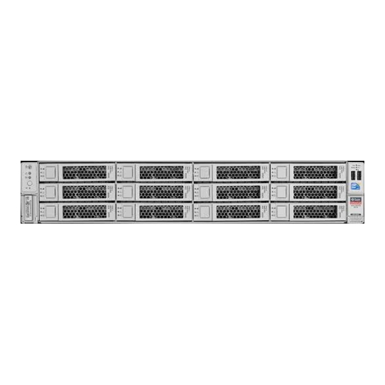
• Data cables: between the boot disk drive and the on-board SATA controller Server Front Panel Features shows front panel features on the Sun Fire X4270 M2 Server with 12, FIGURE 1-1 3.5-inch, storage drives. Sun Fire X4270 M2 Server Service Manual • May 2011... - Page 21 Frequency Identification (RFID) tag Power Button PS (Power Supply) REAR Fault LED Locator LED/Button System Overtemperature Fault LED Service Action Required LED (System Level) USB ports (2) Power/OK LED Disk Configuration Label Chapter 1 Sun Fire X4270 M2 Server Overview...
- Page 22 Sun Fire X4270 M2 Server with 24, FIGURE 1-2 2.5-inch, storage drives. Front Panel Features on Server With 24 Storage Drives FIGURE 1-2 Figure Legend Product Serial Number (PSN) Label and Radio System Overtemperature LED...
-
Page 23: Server Back Panel Features
Gigabit Ethernet Ports (0, 1, 2, 3) PCIe2 Slot 4 USB Ports 2.0 (0, 1) PCIe2 Slot 2 HD-15 Video Port shows back panel features on the Sun Fire X4270 M2 Server with FIGURE 1-4 rear-mounted disk drives. Chapter 1 Sun Fire X4270 M2 Server Overview... -
Page 24: Server Status Indicators And Leds
■ Section 1.5.3, “Storage and Boot Drive LEDs” on page 1-13 ■ Section 1.5.4, “Power Supply LEDs” on page 1-13 ■ Section 1.5.5, “Motherboard LEDs” on page 1-14 ■ 1-10 Sun Fire X4270 M2 Server Service Manual • May 2011... -
Page 25: Server General Status Indicators
• FAST BLINK – Use ILOM to activate this indicator to enable you to locate a particular system quickly and easily. • Pressing the Locate button will toggle LED FAST BLINK on or off. Chapter 1 Sun Fire X4270 M2 Server Overview 1-11... -
Page 26: Server Fan Leds
State Meaning Fan Status None Bicolored: • Amber – There is a fan fault. Amber/Green • Green – Fan is properly installed and functioning correctly. No fan errors detected. 1-12 Sun Fire X4270 M2 Server Service Manual • May 2011... -
Page 27: Storage And Boot Drive Leds
PS fan failure, PS overtemperature, PS over current, or PS over/under voltage. AC OK Green • OFF – No AC power is present. • STEADY ON – Normal operation. Input power is above minimum specification. Chapter 1 Sun Fire X4270 M2 Server Overview 1-13... -
Page 28: Motherboard Leds
If it is determined that a CPU is faulty, pressing the Fault Remind button on the motherboard signals the service processor to light the fault LED(s) associated with the faulted CPU(s). 1-14 Sun Fire X4270 M2 Server Service Manual • May 2011... -
Page 29: Fault Remind Super Capacitor Power Led
This indicator is provided to help prevent service actions on the server’s internal components while the AC line-cords are installed and power is being supplied to the server. Chapter 1 Sun Fire X4270 M2 Server Overview 1-15... - Page 30 1-16 Sun Fire X4270 M2 Server Service Manual • May 2011...
-
Page 31: Preparing To Service The System
Safety Information This section describes important safety information that you need to know prior to removing or installing parts in the Sun Fire X4270 M2 Server. Caution – Hazardous voltage present. Never attempt to run the server with the cover removed. -
Page 32: Required Tools
Follow the electrostatic discharge safety practices as described in this chapter. ■ Required Tools The Sun Fire X4270 M2 Server can be serviced with the following tools: Antistatic wrist strap ■ Antistatic mat ■... -
Page 33: Powering On And Off The Server
Powering On and Off the Server Refer to the following topics in this section to power on and off a server: Section 2.4.1, “Power On the Server” on page 2-3 ■ Section 2.4.2, “Power Off the Server” on page 2-4 ■... -
Page 34: Power Off The Server
The ILOM command-line interface (CLI) prompt appears (->). Depending on the type of problem, you might want to view server status or log files, or run diagnostics before you shut down the server. Sun Fire X4270 M2 Server Service Manual • May 2011... -
Page 35: About The Bios
2. Notify affected users that the server will be shut down. 3. Save any open files and quit all running programs. Refer to your application documentation for specific information. 4. Power down the server. Type: -> stop /SYS (for a Graceful shutdown as defined in TABLE 2-1 ->... -
Page 36: Bios Booting And Setup Considerations
No removable boot media is found No video device No video controller is found Firmware (BIOS) ROM corruption BIOS checksum fails and the boot block is not corrupted System restart System boot initiated Sun Fire X4270 M2 Server Service Manual • May 2011... -
Page 37: Bios Post F1 And F2 Errors
BIOS POST Events (Continued) TABLE 2-2 Boot continues Event Cause on host? Initiated by hard reset Boot process started by hard reset Memory initialization Memory sizing is occurring Does not apply System firmware progress Primary processor initialization Primary CPU initialization Does not apply System firmware progress... - Page 38 • Press F1 to continue. Note - This error message might display if during the SP/BIOS communication an internal error occurs. This error might require you to restart the SP. Sun Fire X4270 M2 Server Service Manual • May 2011...
- Page 39 BIOS POST F1 and F2 Error Messages (Continued) TABLE 2-3 BIOS POST Error Message Error Type Resolution • Primary Slave Hard Disk Error IDE/ATAPI • Press F1 to continue. error • Primary Master Hard Disk Error • Check the SP event log in ILOM for more details.
-
Page 40: How Bios Post Memory Testing Works
3. The BIOS polls the memory controllers for both correctable and non-correctable memory errors and logs those errors into the SP. 4. The message, BMC Responding appears at the end of POST. 2-10 Sun Fire X4270 M2 Server Service Manual • May 2011... -
Page 41: Ethernet Port Device And Driver Naming
2.5.1.4 Ethernet Port Device and Driver Naming The server supports four 10/100/1000BASE-T Gigabit Ethernet ports on the rear of the chassis. For port locations, see FIGURE 1-2 The device naming for the Ethernet interfaces is reported differently by different interfaces and operating systems. See for the physical (BIOS) and logical TABLE 2-4 (operating system) naming conventions used for each interface. -
Page 42: Ethernet Port Booting Priority
Save changes and exit, discard changes and exit, discard changes, or load optimal or fail-safe defaults. Section B.2, “BIOS Setup Utility Menu Screens” on page B-3 for examples of each of these screens. 2-12 Sun Fire X4270 M2 Server Service Manual • May 2011... - Page 43 identifies the sub-menus that you can access from each of the seven FIGURE 2-1 top-level BIOS menus. BIOS Configuration Utility Menu Tree FIGURE 2-1 For an example of the options that are available on the BIOS Setup Utility menus, see Appendix Chapter 2 Preparing to Service the System...
-
Page 44: Bios Setup Utility Hot Keys
Connect to the server using the Oracle ILOM Remote Console. ■ The following procedure describes the steps for accessing the BIOS Setup Utility menus. 2-14 Sun Fire X4270 M2 Server Service Manual • May 2011... -
Page 45: Access Bios Setup Utility Menus
2.5.4.1 Access BIOS Setup Utility Menus 1. Power-on or power-cycle the server. The Boot Option screen appears ( FIGURE 2-2 Boot Option Screen FIGURE 2-2 2. To enter the BIOS Setup Utility, do the following: a. Wait for the last line of the screen output to change to Initializing USB Controllers..Done This will take several seconds. - Page 46 Some screens present a confirmation dialog box that enables unwanted changes to be retracted. 7. On sub-screens that only provide configuration information and cannot be modified, press the Esc key to exit the screen. 2-16 Sun Fire X4270 M2 Server Service Manual • May 2011...
-
Page 47: Configuring Support For Tpm
8. To continue modifying other setup parameters, repeat Step 3 through Step Otherwise, go to Step 9. Press and release the right arrow key until the Exit menu screen appears. 10. Follow the instructions on the Exit menu screen to save or discard your changes and exit the BIOS Setup Utility. - Page 48 Main - System Overview screen FIGURE 2-4 2. In the BIOS Setup Utility screen, select the Advanced menu option. The Advanced Settings screen appears ( FIGURE 2-5 Advanced Settings Screen FIGURE 2-5 2-18 Sun Fire X4270 M2 Server Service Manual • May 2011...
- Page 49 3. In the Advanced Settings screen, select Trusted Computing and press Enter. The Trusted Computing screen appears ( FIGURE 2-6 Trusted Computing Screen FIGURE 2-6 4. In the Trusted Computing screen, select the TCG/TPM Support. A pop-up dialog box appears. 5.
- Page 50 7. In the pop-up tab, set the Execute TPM Command option to Enabled and click The updated Trusted Computing screen appears and shows that the Execute TPM Command setting has changed to Enabled ( FIGURE 2-8 2-20 Sun Fire X4270 M2 Server Service Manual • May 2011...
- Page 51 Execute TPM Command – Setting Enabled FIGURE 2-8 8. Press F10 to save the changes and exit the BIOS Setup Utility. 9. To verify that TPM support is configured, do the following: a. Reboot the server. b. To enter the BIOS Setup Utility, press the F2 key while the system is performing the power-on self-test (POST).
-
Page 52: Configuring Sp Lan Settings
Section 2.5.6.1, “Configure LAN Settings for SP” on page 2-23 ■ Section 2.5.6.2, “Viewing or Setting the Oracle ILOM SP IP Address Using the ■ BIOS Setup Utility” on page 2-24 2-22 Sun Fire X4270 M2 Server Service Manual • May 2011... -
Page 53: Configure Lan Settings For Sp
2.5.6.1 Configure LAN Settings for SP 1. Access the BIOS Setup Utility menus. For instructions, see Section 2.5.4.1, “Access BIOS Setup Utility Menus” on page 2-15. 2. In the BIOS Setup Utility menus, use the arrow keys (or Tab key) to navigate to the Advanced menu. -
Page 54: Viewing Or Setting The Oracle Ilom Sp Ip Address Using The Bios Setup Utility
VGA controller, the disk controller, and the network interface card. Approximately 48 Kbytes remain to be shared by the Option ROMs on all bootable PCI-Express plug-in cards. 2-24 Sun Fire X4270 M2 Server Service Manual • May 2011... -
Page 55: Enable Or Disable Option Rom Settings
2.5.7.1 Enable or Disable Option ROM Settings 1. Access the BIOS Setup Utility menus. For instructions, see Section 2.5.4.1, “Access BIOS Setup Utility Menus” on page 2-15. 2. In the BIOS Setup Utility menus, use the arrow keys (or Tab key) to navigate to the Boot menu. -
Page 56: Updating The Bios Firmware
2. From the front of the server, release the two slide release latches ( FIGURE 2-12 Squeeze the green slide release latches to release the slide rails. 2-26 Sun Fire X4270 M2 Server Service Manual • May 2011... -
Page 57: Removing The Server From The Rack
Slide Release Latches FIGURE 2-12 3. While squeezing the slide release latches, slowly pull the server forward until the slide rails latch. The server is now in the extended maintenance position. Removing the Server From the Rack The server must be removed from the rack to service the following components: Motherboard ■... -
Page 58: Remove Server From The Rack
4. From the front of the server, pull the release tabs forward and pull the server forward until it is free of the rack rails ( FIGURE 2-14 A release tab is located on each rail. 2-28 Sun Fire X4270 M2 Server Service Manual • May 2011... -
Page 59: Using Server Filler Panels
Release Tabs and Slide Assembly FIGURE 2-14 5. Set the server on a sturdy work surface. Using Server Filler Panels Each server is shipped with module-replacement filler panels for CPUs, storage drives, DDR3 memory modules (DDR3 DIMMs), PCIe cards, and power supplies. These filler panels are installed at the factory and must remain in the server until you replace them with a purchased option. -
Page 60: Filler Panel Removal And Installation
2-30 Sun Fire X4270 M2 Server Service Manual • May 2011... -
Page 61: Performing Electrostatic Discharge And Antistatic Prevention Measures
Server Filler Panel Removal and Installation Procedures (Continued) TABLE 2-7 Filler Panel Type Removal Procedure Install Procedure Storage Drive 1. Locate the disk drive filler panel to be 1. Locate the vacant disk drive module slot in removed from the server. the server, then ensure that the release lever on the filler panel is fully opened. -
Page 62: Using An Antistatic Wrist Strap
Antistatic bag used to wrap an Oracle replacement part ■ Oracle ESD mat, part number 250-1088 ■ A disposable ESD mat (shipped with some replacement parts or optional ■ system components) 2-32 Sun Fire X4270 M2 Server Service Manual • May 2011... -
Page 63: Removing The Server's Top Cover
2. Attach an antistatic wrist strap. When servicing or removing server components, attach an antistatic strap to your wrist and then to a metal area on the chassis. 2.10 Removing the Server’s Top Cover The top cover and fan door are integrated. Caution –... - Page 64 [2]. 4. Slide the top cover toward the rear of the server about a 0.5 inch (12 mm) [3]. 5. Lift up and remove the top cover [4]. 2-34 Sun Fire X4270 M2 Server Service Manual • May 2011...
-
Page 65: Removing The Front Cover From A Server With 2.5-Inch Storage Drives
2.11 Removing the Front Cover From a Server with 2.5-Inch Storage Drives Before you can remove the server’s disk backplane, you must first remove the server’s front cover. Note – This procedure only applies to the server with 2.5-inch storage drives. Note –... - Page 66 Removing the Front Cover FIGURE 2-16 2-36 Sun Fire X4270 M2 Server Service Manual • May 2011...
-
Page 67: Servicing Customer-Replaceable Devices
Servicing Customer-Replaceable Devices This chapter describes how to replace the hot-swappable and hot-pluggable customer-replaceable units (CRUs) in the Sun Fire X4270 M2 Server. The following topics are covered in this section: Section 3.1, “Hot-Pluggable Versus Hot-Swappable Devices” on page 3-1 ■... -
Page 68: Hot-Swappable Devices
In the Sun Fire X4270 M2 Server, storage drives are hot-pluggable. To hot-plug a drive you must take the drive offline (to prevent any applications from accessing it, and to remove the logical software links to it) before you can safely remove it. See Section 3.2, “Servicing Storage Drives and Boot Drives”... -
Page 69: Server Storage Drive And Boot Drive Locations
3.2.1 Server Storage Drive and Boot Drive Locations shows the physical drive locations for the Sun Fire X4270 M2 Server with FIGURE 3-2 twelve 3.5-inch hard disk drives. Server Front Panel With Twelve 3.5-inch Drives FIGURE 3-1 Figure Legend HDD2... - Page 70 Sun Fire X4270 M2 Server with FIGURE 3-2 twelve 3.5-inch hard disk drives. Server Front Panel With Twelve 2.5-Inch Drives FIGURE 3-2 Figure Legend shows the physical boot drive locations in the rear of the Sun Fire X4270 FIGURE 3-3 M2 Server.
-
Page 71: Storage Drive And Boot Drive Status Led Reference
3.2.2 Storage Drive and Boot Drive Status LED Reference shows the drive status LEDs. FIGURE 3-4 Storage and Boot Drive Status LEDs FIGURE 3-4 Storage and Boot Drive Status LED Descriptions TABLE 3-1 Legend Symbol Color Lights When... OK to Remove Blue The storage drive can be removed safely during a hot-plug operation. - Page 72 Caution – Whenever you remove a storage drive, you should replace it with another storage drive or a filler panel before you power on the server; otherwise the server might overheat due to improper airflow. Sun Fire X4270 M2 Server Service Manual • May 2011...
- Page 73 Removing the Storage Drive FIGURE 3-5 Chapter 3 Servicing Customer-Replaceable Devices...
-
Page 74: Install Storage Drive
Installing a Storage Drive FIGURE 3-6 4. Close the latch to lock the drive in place. 5. Do one of the following: If you have hot-plugged the drive, configure the storage drive. ■ Sun Fire X4270 M2 Server Service Manual • May 2011... -
Page 75: Remove Boot Drive
For configuration information, refer to TABLE 3-3 Storage Drive Installation Configuration Information TABLE 3-3 HBA Controller Type Refer to... For Sun Storage • LSI MegaRAID SAS Software User’s Guide located at: http://www.lsi.com/support/sun/ Note - Open the book PDF file and search on “drive offline.” For LSI MegaRAID •... -
Page 76: Install Boot Drive
See for drive locations. FIGURE 3-2 3. Slide the drive into the drive slot until it is fully seated ( [1]). FIGURE 3-8 3-10 Sun Fire X4270 M2 Server Service Manual • May 2011... -
Page 77: Servicing Fan Modules
Installing a Rear-Mounted Boot Drive FIGURE 3-8 4. Close the drive latch to lock the drive in place [2]. Servicing Fan Modules The following topics are covered in this section: Section 3.3.1, “About Server Fans” on page 3-12 ■ Section 3.3.2, “Detecting Fan Module Failure” on page 3-12 ■... -
Page 78: About Server Fans
Service Action Required LEDs are also lit if the system detects a fan module fault. Green – Indicates that the fan module is correctly installed and operating within specification. 3-12 Sun Fire X4270 M2 Server Service Manual • May 2011... -
Page 79: Remove Fan Module
3.3.4 Remove Fan Module Caution – Hazardous moving parts. Unless the power to the server is completely shut down, the only service permitted in the fan compartment is the replacement of the fan modules. 1. Extend the server into the maintenance position. Section 2.6, “Extending the Server to the Maintenance Position”... -
Page 80: Install Fan Module
Apply firm, downward pressure to the fan module to fully seat it into the fan power board. 3-14 Sun Fire X4270 M2 Server Service Manual • May 2011... - Page 81 Installing a Fan Module FIGURE 3-10 2. Verify that the Fan Fault status LED for the replaced fan module is lit green FIGURE 3-9 3. Close the top cover door. 4. Verify that the Top Fan LED and the Service Action Required LED on the server’s front panel are extinguished.
-
Page 82: Servicing Power Supplies
Power Supply Status LEDs Each power supply contains status LEDs that are visible on the back of the server provides a description of these LEDs. FIGURE 3-11 TABLE 3-5 3-16 Sun Fire X4270 M2 Server Service Manual • May 2011... - Page 83 Power Supply Status LEDs FIGURE 3-11 Power Supply Status LEDs TABLE 3-5 Legend Symbol Color Lights When... Green DC power is available. The power supply is producing DC power within specifications. Service Action Required Amber The power supply is faulty. The front REAR PS LED and the front and rear panel Service Action Required LEDs the are also lit if the system detects a...
-
Page 84: Remove Power Supply
Releasing the Cable Management Arm FIGURE 3-12 a. Press and hold the CMA release tab. b. Rotate the cable management arm out of the way so that you can access the power supply. 3-18 Sun Fire X4270 M2 Server Service Manual • May 2011... -
Page 85: Install Power Supply
4. Disconnect the power cord from the faulty power supply. 5. Grasp the power supply handle and press the release latch ( [1]). FIGURE 3-13 6. Pull the power supply out of the chassis [2]. Removing a Power Supply FIGURE 3-13 3.4.4 Install Power Supply 1. - Page 86 Note – See Section 1.4, “Server Back Panel Features” on page 1-9 for more information about identifying and interpreting system LEDs. 3-20 Sun Fire X4270 M2 Server Service Manual • May 2011...
-
Page 87: Servicing Motherboard Components
C H A P T E R Servicing Motherboard Components This chapter describes how to replace the motherboard and its components in the Sun Fire X4270 M2 Server. Note – Before performing any of the procedures in this chapter, perform the procedures described in... -
Page 88: Motherboard Component Locations
Motherboard Component Locations The motherboard components that are replaceable are shown in FIGURE 4-1 Location of Motherboard Components FIGURE 4-1 Figure Legend Memory DIMMs Battery PCIe Card CPUs PCIe Riser Sun Fire X4270 M2 Server Service Manual • May 2011... -
Page 89: Servicing Memory Modules (Dimms)
DIMMs, or damage to the DIMMs might occur. You must disconnect all power cables from the system before performing this procedure. The Sun Fire X4270 M2 Server supports a variety of DIMM configurations that can include quad-rank (QR) DIMMs, dual-rank (DR) DIMMs, or single-rank (SR) DIMMs. -
Page 90: Dimm And Cpu Physical Layout
The physical layout of the DIMMs and CPUs is shown in FIGURE 4-2 TABLE 4-1 CPU and DIMM Physical Layout FIGURE 4-2 CPUs and DIMMs Physical Layout TABLE 4-1 CPUs and DIMMs Physical Layout CPU 0 location CPU 1 location Sun Fire X4270 M2 Server Service Manual • May 2011... -
Page 91: Dimm Population Rules
CPUs and DIMMs Physical Layout TABLE 4-1 CPUs and DIMMs Physical Layout Channel locations for CPU 0 Three channels per CPU with each channel containing three color-coded DIMM slots (black, white, and blue). Channel locations for CPU 1 Three channels per CPU with each channel containing three color-coded DIMM slots (blue, white and black). - Page 92 • 1x of the same kind of DIMMs per channel = 1066 MHz (if using 1066 MHz DIMMs) The system operates all memory only as fast as the slowest DIMM configuration. * This DIMM configuration requires CPUs supporting 1333 MHz. Sun Fire X4270 M2 Server Service Manual • May 2011...
-
Page 93: Dimm Rank Classification Labels
4.2.3 DIMM Rank Classification Labels DIMMs come in a variety of ranks: single, dual, or quad. Each DIMM is shipped with rank a label identifying its rank classification. identifies the corresponding TABLE 4-3 classification label shipped with each DIMM. DIMM Classification Labels TABLE 4-3 Rank Classification Label... -
Page 94: Inconsistencies Between Dimm Fault Leds And The Bios Mapping Of Faulty Dimms
Section 2.9, “Performing Electrostatic Discharge and Antistatic Prevention Measures” on page 2-31. d. Remove the top cover. Section 2.10, “Removing the Server’s Top Cover” on page 2-33. 2. Remove the faulty DDR3 DIMM(s). Sun Fire X4270 M2 Server Service Manual • May 2011... - Page 95 a. To identify the location of the faulty DDR3 DIMMS, press the Fault Remind button on the motherboard ( FIGURE 4-3 Note – When the Fault Remind button is pressed, a LED located next to the Fault Remind button lights green to indicate that there is sufficient voltage present in the fault remind circuit to light any fault LEDs that were set due to a failure.
- Page 96 DIMM socket, insert a DIMM filler panel in the socket to ensure adequate cooling and reduce the possibility of a system shutdown. For instructions for installing a DDR3 filler panel, see Section 2.8.2, “Filler Panel Removal and Installation” on page 2-30. 4-10 Sun Fire X4270 M2 Server Service Manual • May 2011...
-
Page 97: Install Ddr3 Dimms
DIMM Socket Release and Alignment FIGURE 4-5 Figure Legend DIMM connector slot DIMM connector key DIMM ejector lever 4.2.7 Install DDR3 DIMMs 1. Unpack the replacement DDR3 DIMMs and place them on an antistatic mat. 2. Ensure that the replacement DIMMs match the sizes as the DIMMs they are replacing. - Page 98 Section 6.2, “Installing the Server Top Cover” on page 6-2. b. Return the server to the normal rack position. Section 6.4, “Returning the Server to the Normal Rack Position” on page 6-5. 4-12 Sun Fire X4270 M2 Server Service Manual • May 2011...
-
Page 99: Error Correction And Parity
Servicing the Air Baffle You must remove the air baffle when removing and installing the motherboard on Sun Fire X4270 M2 Server. Caution – To prevent the system from overheating, ensure that the air baffle is correctly installed before powering on the server. -
Page 100: Open Air Baffle
Section 2.10, “Removing the Server’s Top Cover” on page 2-33. 2. Open the air baffle as shown in FIGURE 4-7 Grasp the air baffle at the bottom and lift it up and out of the way. 4-14 Sun Fire X4270 M2 Server Service Manual • May 2011... -
Page 101: Remove Air Baffle
Opening the Air Baffle FIGURE 4-7 4.3.2 Remove Air Baffle 1. Prepare the server for service. a. Power off the server and disconnect the power cord (or cords) from the server power supply (or supplies). Section 2.4.2, “Power Off the Server” on page 2-4. -
Page 102: Install Air Baffle
1. Install the air baffle into the chassis. a. Press the air baffle connectors outward. b. Insert the air baffle in to the server, and lower it to its down position. 4-16 Sun Fire X4270 M2 Server Service Manual • May 2011... -
Page 103: Servicing Pcie Risers
2. Return the server to operation. a. Install the top cover. Section 6.2, “Installing the Server Top Cover” on page 6-2. b. Return the server to the normal rack position. Section 6.4, “Returning the Server to the Normal Rack Position” on page 6-5. - Page 104 Lift up the riser and any PCIe cards that are attached to it as a unit [2]. The server can have up to three PCIe risers. Each riser can support two PCIe cards. 4-18 Sun Fire X4270 M2 Server Service Manual • May 2011...
-
Page 105: Install Pcie Riser
Removing a PCIe Riser FIGURE 4-9 4.4.2 Install PCIe Riser 1. Lower the PCIe riser and any cards attached to it into the system ( FIGURE 4-10 [1]). Slide the back of the riser into the motherboard back panel stiffener. 2. -
Page 106: Servicing Pcie Cards
Section 4.5.2, “PCIe Card Configuration Guidelines” on page 4-22 ■ Section 4.5.3, “Remove a PCIe Card” on page 4-23 ■ Section 4.5.4, “Install a PCIe Card” on page 4-24 ■ 4-20 Sun Fire X4270 M2 Server Service Manual • May 2011... -
Page 107: Supported Pcie Cards
To determine which SAS PCIe option cards are supported and available for purchase on the Sun Fire X4270 M2 Server, go to the following web site and navigate to the appropriate page: http://www.oracle.com/goto/x4270m2. -
Page 108: Pcie Card Configuration Guidelines
To determine which SAS PCIe option cards are supported and available for purchase on the Sun Fire X4270 M2 Server, go to the following web site and navigate to the appropriate page: http://www.oracle.com/goto/x4270m2. -
Page 109: Remove A Pcie Card
4.5.3 Remove a PCIe Card 1. Prepare the server for service. a. Power off the server and disconnect the power cord (or cords) from the power supply (or supplies). Section 2.4.2, “Power Off the Server” on page 2-4. b. Extend the server to the maintenance position. Section 2.6, “Extending the Server to the Maintenance Position”... -
Page 110: Install A Pcie Card
10. Use ILOM to clear the server PCIe card fault. For instructions for clearing an PCIe card faults, see the Oracle Integrated Lights Out Manager (ILOM) 3.0 Supplement for Sun Fire X4170 M2 and X4270 M2 Servers (821-0489). 4-24 Sun Fire X4270 M2 Server Service Manual • May 2011... -
Page 111: Servicing The Server Battery
11. To determine if additional steps are required to complete the installation of the PCIe card, see the hardware installation guide for the type of PCIe card you installed. for a listing of the PCIe host bus adapter (HBA) cards supported by TABLE 4-5 the server and references to the applicable installation guide. -
Page 112: Install Battery
4. If the service processor is not configured to use NTP, you must reset the ILOM clock using the ILOM CLI or the web interface. For instructions, see the Sun Integrated Lights Out Manager (ILOM) 3.0 Documentation Collection. 5. Return the server to operation. 4-26 Sun Fire X4270 M2 Server Service Manual • May 2011... -
Page 113: Servicing Cpus
a. Install the top cover. Section 6.2, “Installing the Server Top Cover” on page 6-2. b. Return the server to the normal rack position. Section 6.4, “Returning the Server to the Normal Rack Position” on page 6-5. c. Reconnect the power cord (or cords) to the power supply (or supplies) and power on the server. - Page 114 This can happen if the Fault Remind button is pressed for a long time with fault LEDs lit or if power has been removed from the server for more than 15 minutes. 4-28 Sun Fire X4270 M2 Server Service Manual • May 2011...
- Page 115 CPU Fault LEDs Locations FIGURE 4-12 If CPU LED is off: CPU is operating properly. ■ If CPU LED is on (amber): CPU is faulty and should be replaced. ■ CPU0 is closest to power supply bay ( [1]). FIGURE 4-13 b.
- Page 116 CPU heat sink; otherwise the server might overheat due to improper airflow. For instructions for installing a CPU filler panel, see Section 2.8.2, “Filler Panel Removal and Installation” on page 2-30. 4-30 Sun Fire X4270 M2 Server Service Manual • May 2011...
-
Page 117: Install Cpu
Removing the CPU FIGURE 4-13 4.7.2 Install CPU Two procedures are provide here for installing the CPU: A procedure to use when you replace a CPU that has failed. ■ Section 4.7.2.1, “Replace Faulty CPU” on page 4-32 A procedure for installing a second CPU in a server that previously had only one ■... -
Page 118: Replace Faulty Cpu
CPU or a filler panel and reinstall the CPU heat sink; otherwise the server might overheat due to improper airflow. For instructions for installing a CPU filler panel, seeSection 2.8.2, “Filler Panel Removal and Installation” on page 2-30. 4-32 Sun Fire X4270 M2 Server Service Manual • May 2011... - Page 119 Installing the CPU. FIGURE 4-14 b. Lower the pressure frame [2]. Ensure that the pressure frame sits flat around the periphery of the CPU. c. Engage the release lever by rotating it downward and slipping it under the catch [2]. d.
-
Page 120: Upgrade Server To Two Cpus
Caution – CPU options should be installed only by a Sun qualified service technician. 1. Attach an antistatic wrist strap. Section 2.9, “Performing Electrostatic Discharge and Antistatic Prevention Measures” on page 2-31. 4-34 Sun Fire X4270 M2 Server Service Manual • May 2011... - Page 121 2. Unpack the CPU kit. The kit includes a CPU chip and a heatsink with the thermal grease pre-applied. 3. Install the CPU ( FIGURE 4-14 a. Properly orient the CPU with the socket alignment tabs and carefully place the CPU into the socket [1]. Ensure that the orientation is correct as damage might result if the CPU pins are not aligned correctly.
-
Page 122: Servicing The Motherboard
Section 2.7, “Removing the Server From the Rack” on page 2-27. c. Attach an antistatic wrist strap. Section 2.9, “Performing Electrostatic Discharge and Antistatic Prevention Measures” on page 2-31. 4-36 Sun Fire X4270 M2 Server Service Manual • May 2011... - Page 123 d. Remove the top cover from the server. Section 2.10, “Removing the Server’s Top Cover” on page 2-33. 2. Remove the plastic air baffle. Section 4.3.2, “Remove Air Baffle” on page 4-15. 3. Disconnect the SAS storage drive cables from the SAS PCIe card or the on-board SATA connectors located on the motherboard.
-
Page 124: Install Motherboard
Install the four Phillips screws that secure the motherboard to the bus bar [1]. c. Tighten the green captive screw on the front of the motherboard that secures the motherboard to the chassis [1]. 4-38 Sun Fire X4270 M2 Server Service Manual • May 2011... - Page 125 Installing the Motherboard FIGURE 4-16 3. If you are replacing the motherboard because it failed and needed to be replaced, you can now reinstall the reusable components. Reusable motherboard components are as follows: Memory DIMMS. For instructions, see Section 4.2.7, “Install DDR3 DIMMs” on ■...
-
Page 126: Resetting Passwords And Clearing Cmos Nvram
Section 2.9, “Performing Electrostatic Discharge and Antistatic Prevention Measures” on page 2-31. The following topics are covered: Section 4.9.1, “Overview” on page 4-41 ■ 4-40 Sun Fire X4270 M2 Server Service Manual • May 2011... -
Page 127: Overview
Section 4.9.2, “Reset the BIOS Password and Clear the CMOS NVRAM Using the ■ CLR CMOS Button” on page 4-41 4.9.1 Overview You can clear the CMOS NVRAM and BIOS password by pressing the CLR CMOS button, which is located on the motherboard. You can also reset the BIOS passwords from the BIOS Setup Utility. - Page 128 Section 6.5, “Powering On the Server” on page 6-7. The BIOS password is reset to the default and the CMOS NVRAM is cleared. Verify that the AC Present LED is lit. 4-42 Sun Fire X4270 M2 Server Service Manual • May 2011...
-
Page 129: Servicing Infrastructure Components
C H A P T E R Servicing Infrastructure Components This chapter describes how to replace cold-swappable, field-replaceable units (FRUs) in the Sun Fire X4270 M2 Server. The following topics are covered: Section 5.1, “Infrastructure Component Locations” on page 5-2 ■... -
Page 130: Infrastructure Component Locations
FIGURE 5-1 Location of Infrastructure Components FIGURE 5-1 Figure Legend Fan Board Power Distribution Board SAS Expander Board Connector Board Disk Backplane Power Supply Backplane Front control Panel Light Pipe Assembly Sun Fire X4270 M2 Server Service Manual • May 2011... -
Page 131: Servicing The Sas Expander Board
Servicing the SAS Expander Board Caution – Ensure that all power is removed from the server before removing or installing the SAS expander board. You must disconnect the power cables before performing these procedures. 5.2.1 Remove the SAS Expander Board 1. - Page 132 SAS expander card [5]. Note – The SAS expander card and its holding bracket are replaced as a unit. f. Place the SAS expander board with its bracket on an antistatic mat. Sun Fire X4270 M2 Server Service Manual • May 2011...
- Page 133 Removing the SAS Expander Board (Servers With 3.5-Inch Storage Drives) FIGURE 5-2 Chapter 5 Servicing Infrastructure Components...
-
Page 134: Install Sas Expander Board
Verify that the AC Present LED is lit. Servicing the Fan Board You must remove the fan board to access the storage drive data cable in the Sun Fire X4270 M2 Server Sun Fire X4270 M2 Server Service Manual • May 2011... -
Page 135: Remove Fan Board
Caution – Ensure that all power is removed from the server before removing or installing fan board. You must disconnect the power cables before performing this procedure. 5.3.1 Remove Fan Board 1. Prepare the server for service. a. Power off the server and disconnect the power cord (or cords) from the power supply (or supplies). -
Page 136: Install Fan Board
Lower the fan board into place in the chassis floor and slide it toward the rear of the server to engage the mushroom standoffs [4]. b. Secure the fan board to the chassis with the two green captive screws [2]. Sun Fire X4270 M2 Server Service Manual • May 2011... -
Page 137: Servicing The Disk Backplane
a. Connect the signal cable to the fan board [2). b. Reconnect the fan power cable [1]. 2. Install the SAS expander module. Section 5.2.2, “Install SAS Expander Board” on page 5-6. 3. Reinstall the fan modules. Section 3.3.5, “Install Fan Module” on page 3-14. - Page 138 Remove the cable cover ( FIGURE 5-4 To remove the cable cover, lift it up approximately 4mm, slide it forward, and lift it up and out of the server. 5-10 Sun Fire X4270 M2 Server Service Manual • May 2011...
- Page 139 Removing the Cable Cover (Only Required on Servers With 3.5-Inch Storage FIGURE 5-4 Drives) 6. Remove the disk backplane ( FIGURE 5-5 a. Disconnect the two power cables [1]. b. Disconnect the front panel light pipe cables [2]. There are two light pipe cables, one on either side of the backplane. c.
-
Page 140: Install Disk Backplane
Install the two green, No. 2 Phillips screws that secure the disk backplane to the server chassis [3]. c. Connect the signal cable to the disk backplane [2]. 5-12 Sun Fire X4270 M2 Server Service Manual • May 2011... -
Page 141: Servicing The Front Panel Led Modules
d. Connect the two light pipe cables to the disk backplane [2]. There are two light pipe cables, one on either side of the backplane. e. Connect the two power cables to the disk backplane [1]. 2. Install the SAS expander board. Section 5.2.2, “Install SAS Expander Board”... -
Page 142: Remove The Right Led/Usb Module
[3]. e. Slide the LED/USB module back and away from the server’s front panel [3]. f. Guide the LED/USB flex cable out through the chassis side wall [4]. 5-14 Sun Fire X4270 M2 Server Service Manual • May 2011... -
Page 143: Install The Right Led/Usb Module
Removing the Right LED/USB Module FIGURE 5-6 5.5.2 Install the Right LED/USB Module 1. Install the right LED/USB module ( FIGURE 5-7 a. Insert the LED/USB flex cable in through the opening chassis side wall [4]. b. Position the LED/USB module on the server’s front panel [3]. c. -
Page 144: Remove The Left Led Module
Section 2.11, “Removing the Front Cover From a Server with 2.5-Inch Storage Drives” on page 2-35. 2. Remove the left LED Module ( FIGURE 5-7 5-16 Sun Fire X4270 M2 Server Service Manual • May 2011... -
Page 145: Install The Left Led Module
a. Remove the No. 2 Phillips screw that secures the LED module to the server front panel [1]. b. Disconnect the LED module cable from the disk backplane and gently pull it through the side wall of the server chassis [2]. c. -
Page 146: Servicing The Power Distribution Board
Verify that the AC Present LED is lit. Servicing the Power Distribution Board On the Sun Fire X4270 M2 Server, you do not need to remove the motherboard to service the power distribution board. Caution – The server supplies power to the power distribution board even when the server is powered off. - Page 147 c. Attach an antistatic wrist strap. Section 2.9, “Performing Electrostatic Discharge and Antistatic Prevention Measures” on page 2-31. d. Remove the top cover. Section 2.10, “Removing the Server’s Top Cover” on page 2-33. 2. Remove the power distribution board ( FIGURE 5-8 a.
-
Page 148: Install Power Distribution Board
The power distribution board fits over a series of mushroom standoffs in the floor of the chassis. b. Slide the power distribution board toward the chassis wall until it plugs into the connector board [4]. 5-20 Sun Fire X4270 M2 Server Service Manual • May 2011... -
Page 149: Servicing The Connector Board
c. Install five No. 2 Phillips screws to secure the power distribution board to the bus bar [3]. d. Install the four No. 2 Phillips screws to secure the power distribution board to the chassis [3]. e. Connect the power supply ribbon cable to the power distribution board [2]. f. - Page 150 Disconnect the disk backplane signal cable from the connector board [4]. e. Remove the two straight-edge screws that secure the connector board bracket to the server’s mid wall [5]. 5-22 Sun Fire X4270 M2 Server Service Manual • May 2011...
- Page 151 Removing the Connector Board FIGURE 5-9 Chapter 5 Servicing Infrastructure Components 5-23...
-
Page 152: Install Connector Board
Section 5.6.2, “Install Power Distribution Board” on page 5-20. 6. Return the server to operation. a. Install the top cover. Section 6.2, “Installing the Server Top Cover” on page 6-2. 5-24 Sun Fire X4270 M2 Server Service Manual • May 2011... -
Page 153: Servicing The Power Supply Backplane
b. Return the server to the normal rack position. Section 6.4, “Returning the Server to the Normal Rack Position” on page 6-5. c. Reconnect the power cord (or cords) to the power supply (or supplies) and power on the server. Section 6.5, “Powering On the Server”... -
Page 154: Install Power Supply Backplane
To secure the power supply backplane to the server chassis, install the Phillips screw [1]. c. Reconnect the power supply ribbon cable to the power supply backplane [1]. 5-26 Sun Fire X4270 M2 Server Service Manual • May 2011... -
Page 155: Servicing The Rear-Mounted Boot Disk Drive Cage
7. Install the power distribution board. Section 5.6.2, “Install Power Distribution Board” on page 5-20. 8. Install the power supplies. Section 3.4.4, “Install Power Supply” on page 3-19. 9. Return the server to operation. a. Install the top cover. Section 6.2, “Installing the Server Top Cover” on page 6-2. - Page 156 Remove the two green captive screws that secure the boot disk drive cage to the server chassis [3]. f. Lift the cage up and out of the chassis [4]. 3. Place the cage on an antistatic mat. 5-28 Sun Fire X4270 M2 Server Service Manual • May 2011...
-
Page 157: Install The Rear-Mounted Boot Disk Drive Cage
Removing the Rear-Mounted Boot Disk Drive Cage FIGURE 5-11 5.9.2 Install the Rear-Mounted Boot Disk Drive Cage 1. Install the rear-mounted boot disk drive cage ( FIGURE 5-11 a. Lower the boot disk drive cage into the server chassis [4]. b. -
Page 158: Servicing Cables
To avoid personal injury or damage to the server, you must disconnect power cords before servicing the cables. 5.10.1 Remove Storage Drive Cable in a SAS Configuration 1. Prepare the server for service. 5-30 Sun Fire X4270 M2 Server Service Manual • May 2011... - Page 159 a. Power off the server and disconnect the power cord (or cords) from the power supply (or supplies). Section 2.4.2, “Power Off the Server” on page 2-4. b. Extend the server to the maintenance position. Section 2.6, “Extending the Server to the Maintenance Position” on page 2-26.
- Page 160 [1] on the SAS expander board (as viewed from the from the front of the server) connects to right connector [1] on the HBA card, and vice versa. 5-32 Sun Fire X4270 M2 Server Service Manual • May 2011...
- Page 161 Removing Storage Drive Cable From a Server With the Rear-Mounted Disk FIGURE 5-13 Drive Cage Installed Note – In the above figure, , the numbered call outs (1, 2) highlight that FIGURE 5-13 the cable that connects to the left connector [1] on the SAS expander board (as viewed from the from the front of the server) connects to right connector [1] on the HBA card, and vice versa.
-
Page 162: Install Storage Drive Cable In A Sas Configuration
1. Prepare the server for service. a. Power off the server and disconnect the power cord (or cords) from the power supply (or supplies). Section 2.4.2, “Power Off the Server” on page 2-4. 5-34 Sun Fire X4270 M2 Server Service Manual • May 2011... -
Page 163: Install Power Distribution Board Cable
b. Extend the server to the maintenance position. Section 2.6, “Extending the Server to the Maintenance Position” on page 2-26. c. Attach an antistatic wrist strap. Section 2.9, “Performing Electrostatic Discharge and Antistatic Prevention Measures” on page 2-31. d. Remove the top cover. Section 2.10, “Removing the Server’s Top Cover”... - Page 164 Reconnect the power cord (or cords) to the power supply (or supplies) and power on the server. Section 6.5, “Powering On the Server” on page 6-7. Verify that the AC Present LED is lit. 5-36 Sun Fire X4270 M2 Server Service Manual • May 2011...
-
Page 165: Returning The Server To Operation
C H A P T E R Returning the Server to Operation This chapter describes how to return the Sun Fire X4270 M2 Server to operation after you have performed service procedures. The following topics are covered in this chapter: Section 6.1, “Installing the Front Cover Onto a Server with 2.5-Inch Storage... -
Page 166: Install The Server Front Cover
If you removed the top cover, perform the following procedure to replace it. 6.2.1 Install the Server Top Cover 1. Place the top cover on the chassis ( [1]). FIGURE 6-2 Sun Fire X4270 M2 Server Service Manual • May 2011... - Page 167 Ensure that the rear interlocks on both sides of the top cover engage the slots on both sides of the server’s chassis. Installing the Top Cover on the Sun Fire X4270 M2 Server FIGURE 6-2 2. Slide the top cover forward until it seats [2].
-
Page 168: Reinstalling The Server In The Rack
3. Insert the mounting brackets into the slide-rails, then push the server into the rack until the mounting brackets encounter the slide-rail stops (approximately 12 inches, or 30 cm). The server is now in the extended maintenance position. Sun Fire X4270 M2 Server Service Manual • May 2011... -
Page 169: Returning The Server To The Normal Rack Position
Returning the Server to the Rack FIGURE 6-3 Returning the Server to the Normal Rack Position If you extended the server to the maintenance position, use this procedure to return the server to the normal rack position. Chapter 6 Returning the Server to Operation... -
Page 170: Return The Server To The Normal Rack Position
4. Reconnect the cables to the back of the server. If the cable management arm (CMA) is in the way, disconnect the left CMA release and swing the CMA open. Sun Fire X4270 M2 Server Service Manual • May 2011... -
Page 171: Powering On The Server
5. Reconnect the CMA. Swing the CMA closed and latch it to the left rack rail. Powering On the Server Before powering on your server for the first time, follow the installation and cabling instructions provided in the Sun Fire X4170 M2 and X4270 M2 Servers Installation Guide (821-0481), which is optionally shipped with the system and is also available online at: http://docs.sun.com/app/docs/prod/sf.x4270m2#hic... - Page 172 Sun Fire X4270 M2 Server Service Manual • May 2011...
-
Page 173: Troubleshooting The Server And Restoring Ilom Defaults
C H A P T E R Troubleshooting the Server and Restoring ILOM Defaults This chapter introduces the diagnostic tools you can use to troubleshoot or monitor the performance of your server. It also includes information about how to restore the service processor (SP) password and serial connection defaults in Oracle Integrated Lights Out Manager (ILOM), as well as how to restore your ILOM SP firmware. -
Page 174: Troubleshooting The Server
The diagnostic tools range from standalone software packages, to firmware-based tests like power-on self-test (POST), U-Boot tests, or Pc-Check tests, to hardware LEDs that tell you when the system components are operating. Sun Fire X4270 M2 Server Service Manual • May 2011... - Page 175 summarizes the variety of diagnostic tools that you can use when TABLE 7-1 troubleshooting or monitoring your server. Summary of Oracle Diagnostic Tools TABLE 7-1 Diagnostic Tool Type What It Does Accessibility Remote Capability Integrated Lights Monitors environmental Can function on standby Designed for Out Manager firmware...
-
Page 176: Diagnostic Tool Documentation
Locate the latest version of these guides at: http://docs.sun.com/app/docs/prod/sf.x4270m2#hic POST • Section 2.5.1.1, “Default BIOS Power-On Self-Test (POST) Events” on page 2-6 • Section 2.5.1.2, “BIOS POST F1 and F2 Errors” on page 2-7 Sun Fire X4270 M2 Server Service Manual • May 2011... -
Page 177: Using The Preboot Menu Utility
Summary of Documentation for Oracle Diagnostic Tools (Continued) TABLE 7-2 Diagnostic Tool Where to Find Information U-Boot • Oracle x64 Servers Diagnostics Guide Locate the latest copy of this guide at: http://docs.sun.com/app/docs/prod/sf.x4270m2#hic Pc-Check Oracle Solaris Locate the latest Oracle Solaris command information for Solaris 10 at: commands http://docs.sun.com/app/docs/doc/817-0550/eqxqt?a=view SunVTS... -
Page 178: Prerequisites For Accessing The Preboot Menu
Use a remote serial terminal or console running terminal emulation software to access the Preboot Menu remotely. Note – You cannot use an SSH, or a remote KVMS session to access the Preboot Menu remotely. Sun Fire X4270 M2 Server Service Manual • May 2011... -
Page 179: Access The Preboot Menu
7.2.1.2 Access the Preboot Menu 1. Ensure that the requirements in Section 7.2.1.1, “Prerequisites for Accessing the Preboot Menu” on page 7-6 are met. 2. Reset ILOM. For example: From the server SP ILOM, enter the command: ■ -> reset /SP ILOM reboots and messages begin scrolling on the screen. -
Page 180: Edit Preboot Menu For Remote Serial Access
6. Press Enter to move through the settings until the check_physical_presence setting appears. To change the check_physical_presence setting, type no, then press Enter. The Preboot Menu displays the check_physical_presence setting with the new value. Sun Fire X4270 M2 Server Service Manual • May 2011... - Page 181 7. Press Enter for the new value to take effect. The Preboot Menu asks you to confirm your changes. Enter ‘y[es]’ to commit changes: [no] 8. Type y to save your changes and exit the edit session. If you want to exit the edit session without saving your changes, type n. 9.
-
Page 182: Edit Mode Settings In Preboot Menu
1. Access the Preboot Menu as described in Section 7.2.1.2, “Access the Preboot Menu” on page 7-7. 2. At Preboot Menu prompt, type: Preboot> unconfig ilom_conf Setting ‘preserve_conf’ to ‘no’ for the next boot of ILOM. 7-10 Sun Fire X4270 M2 Server Service Manual • May 2011... -
Page 183: Restoring Ilom Access To The Serial Console
3. Reset the SP by typing: Preboot> boot The Preboot Menu exits and the SP restarts. After restarting the ILOM SP, the value for ILOM settings revert to their defaults. 7.2.3 Restoring ILOM Access to the Serial Console In the event that the serial connection between ILOM and a host becomes unavailable, you can restore access to the serial port connection by reconfiguring the host as the external serial port owner in either the ILOM web interface or CLI, or in the Preboot Menu. -
Page 184: Restoring The Sp Firmware Image
The following requirements must be met prior to restoring the SP firmware on your server using the Preboot Menu. You must be a qualified service technician to perform this procedure. ■ 7-12 Sun Fire X4270 M2 Server Service Manual • May 2011... -
Page 185: Restore The Sp Firmware Image Using The Preboot Menu
You must have a valid .flash firmware image file on a TFTP server. ■ Note – Restore the SP firmware using the Preboot Menu requires a .flash file instead of a.pkg file that is typically used to update the SP using the ILOM interfaces. -
Page 186: Preboot Menu Command Summary
Caution - If you start the host when ILOM is off, the BIOS does not send error events, or power messages to the SP. This can cause the server to lose power. • hard-off – Turns the host off. 7-14 Sun Fire X4270 M2 Server Service Manual • May 2011... - Page 187 Preboot Menu Commands (Continued) TABLE 7-4 Command Description { config | dhcp | ping | flash } • config – Starts a dialog that enables you to change the ILOM network settings. • dhcp – Changes the network addressing from static to DHCP. Note - You must set ipdiscovery = dhcp using the net config command first.
- Page 188 7-16 Sun Fire X4270 M2 Server Service Manual • May 2011...
-
Page 189: Connector Pinouts
A P P E N D I X Connector Pinouts This appendix provides reference information about the Sun Fire X4270 M2 Server back panel ports and pin assignments. Topics covered in this appendix include: Section A.1, “Serial Management Port Connector” on page A-2 ■... -
Page 190: Serial Management Port Connector
This port is the default connection to the system console. Serial Management Connector Diagram FIGURE A-1 Figure Legend Request to Send Ground Data Terminal Ready Receive Data Transmit Data Data Set Ready Ground Clear to Send Sun Fire X4270 M2 Server Service Manual • May 2011... -
Page 191: Network Management Port Connector
Network Management Port Connector The network management connector (labeled NET MGT) is an RJ-45 connector located on the motherboard and can be accessed from the back panel. This port needs to be configured prior to its use. Network Management Connector Diagram FIGURE A-2 Figure Legend Transmit Data +... -
Page 192: Video Connector
Blue Video Monitor ID - Bit 1 Monitor ID - Bit 2 Monitor ID - Bit 0 Ground Horizontal Sync Red Ground Vertical Sync Green Ground N/C (Reserved) Blue Ground Sun Fire X4270 M2 Server Service Manual • May 2011... -
Page 193: Usb Connectors
USB Connectors Two Universal Serial Bus (USB) ports are located on the motherboard and can be accessed from the server back panel. USB Connector Diagram FIGURE A-4 Figure Legend USB 0-1 +5 V (fused) USB 1-1 +5 V (fused) USB 0-2 USB0/1- USB 1-2 USB2/3-... -
Page 194: Gigabit Ethernet Connectors
Transmit/Receive Data 0 + Transmit/Receive Data 2 – Transmit/Receive Data 0 – Transmit/Receive Data 1 – Transmit/Receive Data 1 + Transmit/Receive Data 3 + Transmit/Receive Data 2 + Transmit/Receive Data 3 – Sun Fire X4270 M2 Server Service Manual • May 2011... -
Page 195: Configuring Bios Settings
A P P E N D I X Configuring BIOS Settings This appendix describes how to view and/or modify the Basic Input/Output System (BIOS) settings on the . The BIOS Setup Utility reports system information and server can be used to configure the server BIOS settings. Note –... -
Page 196: Bios Setup Screens Overview
Screen” on page B-10 fail-safe defaults. Section B.2, “BIOS Setup Utility Menu Screens” on page B-3 for examples of each of these screens. Sun Fire X4270 M2 Server Service Manual • May 2011... -
Page 197: Bios Setup Utility Menu Screens
BIOS Setup Utility Menu Screens This section shows samples of the BIOS Setup Utility screens. All screens reflect the optimal defaults at startup. Note – The screens shown are examples. The version numbers and the screen content and selections shown are subject to change over the life of the product. The following topics are covered: Section B.2.1, “BIOS Main Menu Screens”... -
Page 198: Bios Main Menu Screens
The BIOS Main screens provide general product information, including BIOS, processor, system memory, and system time/date. shows the BIOS Main FIGURE B-1 top-level screen. BIOS Setup Utility: Main – System Overview FIGURE B-1 Sun Fire X4270 M2 Server Service Manual • May 2011... -
Page 199: Bios Advanced Menu Screens
B.2.2 BIOS Advanced Menu Screens The BIOS Advanced screens provide detailed configuration information for the CPU, memory, IDE, Super IO, trusted computing, USB, PCI, MPS and other system information. shows the BIOS Advanced top-level screen. FIGURE B-2 BIOS Setup Utility: Advanced – Advanced Settings FIGURE B-2 Appendix B Configuring BIOS Settings... -
Page 200: Bios Pci Menu Screen
The BIOS PCI screen enables you to configure the server to clear NVRAM during system boot. shows the BIOS PCI screen. FIGURE B-3 BIOS Setup Utility: PCI – Advanced PCI Settings FIGURE B-3 Sun Fire X4270 M2 Server Service Manual • May 2011... -
Page 201: Bios Boot Menu Screens
B.2.4 BIOS Boot Menu Screens The BIOS Boot screens enable you to configure the boot device priority (storage drives and the DVD-ROM drive). shows the BIOS Boot top-level screen. FIGURE B-4 BIOS Setup Utility: Boot – Boot Settings FIGURE B-4 Appendix B Configuring BIOS Settings... -
Page 202: Bios Security Menu Screen
The BIOS Security screen enables you to set or change the supervisor and user passwords. shows the BIOS Security screen. FIGURE B-5 BIOS Setup Utility: Security – Security Settings FIGURE B-5 Sun Fire X4270 M2 Server Service Manual • May 2011... -
Page 203: Bios Chipset Menu Screens
B.2.6 BIOS Chipset Menu Screens The BIOS Chipset screens enable you to set the chipset parameters. shows FIGURE B-6 the BIOS Chipset top-level screen. BIOS Setup Utility: Chipset – Advanced Chipset Settings FIGURE B-6 Appendix B Configuring BIOS Settings... -
Page 204: Bios Exit Menu Screen
FIGURE B-8 Note – The confirmation dialog box is only shown below for the Save Changes and Exit option screen. The other exit confirmation screens work in a similar way. B-10 Sun Fire X4270 M2 Server Service Manual • May 2011... - Page 205 BIOS Setup Utility: Exit – Save Configuration Changes and Exit Confirmation FIGURE B-8 Appendix B Configuring BIOS Settings B-11...
- Page 206 B-12 Sun Fire X4270 M2 Server Service Manual • May 2011...
- Page 207 Index considerations and limitations, 4-6 ECC errors, 4-13 Advanced Menu BIOS screen, 2-12 error correction, 4-13 antistatic mat, 2-32 FAULT REMIND button, 4-9 antistatic wrist strap, 2-31, 2-32 parity, 4-13 physical layout, 4-4 population rules, 4-5 BIOS for maximum performance, 4-6 boot option screen, 2-15 speed rules, 4-6 configuring, 2-5...
- Page 208 3-8, 3-10 PCI-E and PCI-X cards, 4-23 hard drive backplane, 5-12 power distribution board, 5-18 motherboard assembly, 4-38 server from rack, 2-27 PCI-E and PCI-X cards, 4-24 Index-2 Sun Fire X4270 M2 Server Service Manual • January 2012...
- Page 209 removing a hard drive, 3-5, 3-9 required tools, 2-2 root password resetting, 7-10 sample BIOS setup screens, B-3 SAS expander board, 5-3, 5-6 Security Menu BIOS screen, 2-12 serial connection to ILOM restoring, 7-11 Service Action Required LED, 3-15, 3-16 Service Required LED, 3-12 servicing cables, 5-30 servicing CPUs, 4-40...
- Page 210 Index-4 Sun Fire X4270 M2 Server Service Manual • January 2012...
Need help?
Do you have a question about the Sun Fire X4270 M2 and is the answer not in the manual?
Questions and answers