Table of Contents
Advertisement
Quick Links
Advertisement
Table of Contents

Related Manuals for Xantrex XDC 10-600


Summary of Contents for Xantrex XDC 10-600
- Page 1 Artisan Technology Group is your source for quality new and certified-used/pre-owned equipment SERVICE CENTER REPAIRS WE BUY USED EQUIPMENT • FAST SHIPPING AND DELIVERY Experienced engineers and technicians on staff Sell your excess, underutilized, and idle used equipment at our full-service, in-house repair center We also offer credit for buy-backs and trade-ins •...
-
Page 2: Dc Power Supply
XDC 10-600 XDC 10-1200 XDC 20-300 XDC 20-600 XDC 30-200 XDC 30-400 XDC 40-150 XDC 40-300 XDC 60-100 XDC 60-200 XDC 80-75 XDC 80-150 XDC 100-60 XDC 100-120 XDC 150-40 XDC 150-80 XDC 300-20 XDC 300-40 XDC 600-10 XDC 600-20... - Page 3 Artisan Technology Group - Quality Instrumentation ... Guaranteed | (888) 88-SOURCE | www.artisantg.com...
- Page 4 Operating Manual for XDC 6000 Watt and 12000 Watt Series Digital Programmable DC Power Supply Artisan Technology Group - Quality Instrumentation ... Guaranteed | (888) 88-SOURCE | www.artisantg.com...
- Page 5 What will Xantrex do? Xantrex will, at its option, repair or replace the defective product free of charge, provided that you notify Xantrex of the product defect within the Warranty Period, and provided that Xantrex through inspection establishes the existence of such a defect and that it is covered by this Limited Warranty.
- Page 6 Xantrex or its authorized service centers (hereafter “ASCs”);...
- Page 7 LIMITED IN DURATION TO THE PERIOD STIPULATED UNDER THIS LIMITED WARRANTY. IN NO EVENT WILL XANTREX BE LIABLE FOR ANY SPECIAL, DIRECT, INDIRECT, INCIDENTAL OR CONSEQUENTIAL DAMAGES, LOSSES, COSTS OR EXPENSES HOWEVER ARISING WHETHER IN CONTRACT OR TORT INCLUDING WITHOUT...
- Page 8 Please refer to your product user manual for limitations on uses of the product. Specifically, please note that this power supply is not intended for use in connection Limitations with life support systems and Xantrex makes no warranty or representation in on Use connection with any use of the product for such purposes.
- Page 9 Warnings Warnings and cautions are defined and formatted in this manual as shown below. Cautions WARNING Describes a potential hazard which could result in injury or death, or, a procedure which, if not performed correctly, could result in injury or death. CAUTION Describes a procedure which, if not performed correctly, could result in damage to data, equipment, or systems.
- Page 10 Symbols Used in This Earth (Ground) Terminal Manual Protective Conductor Terminal On (Supply) Off (Supply) Warning (Shock Hazard) Caution (Check manual for specific information.) Release 3.0 Artisan Technology Group - Quality Instrumentation ... Guaranteed | (888) 88-SOURCE | www.artisantg.com...
- Page 11 Approvals CE Mark CE-marked units meet the following standards: • IEC 1010-1-92 including Amendments 1 and 2: • Overvoltage Category II • Permanently Connected Equipment • EN50081-2-1996 Electromagnetic Generic Emission - Industrial Equivalent • EN50082-2-1995 Electromagnetic Compatibility Generic Immunity - Industrial Environment CSA Certified CSA C22.2 No.
- Page 12 About This Manual Who Should Use This Manual This manual is designed for users who understand basic electrical theory, especially as applied to the operation of power supplies. This implies a recognition of constant voltage and constant current operating modes and the control of input and output power, as well as the observance of safe techniques while making connections to the supply and any changes in settings.
- Page 13 About This Manual Appendix B: SCPI Command Reference describes the Standard Commands for Programmable Instruments (SCPI) commands supported by this model. Appendix C: Error Messages describes the error messages that could appear during operation. describes the General Purpose Interface Bus (GPIB) Appendix D: GPIB commands and lines supported by this model.
-
Page 14: Table Of Contents
Contents About This Manual ........... . ix List of Tables . - Page 15 Contents Load Connections ........... 50 Wire Size .
- Page 16 Contents Program Auto Sequence ......... . 87 Programming a Sequence .
- Page 17 Contents Enable Output ..........128 Program V,I,P .
- Page 18 Contents Appendix B. SCPI Command Reference Overview............193 Codes and Standards .
- Page 19 Contents Appendix D. GPIB Overview ............223 Codes and Standards .
-
Page 20: List Of Tables
List of Tables Table 1.1 Front Panel Functions ........26 Table 2.1 Basic Setup Procedure . - Page 21 List of Tables Table B.10 Status Commands ........205 Table B.11 Protection Commands .
-
Page 22: List Of Figures
List of Figures Figure 1.1 Front Panel (6000 Watt) ........22 Figure 1.2 Front Panel (12000 Watt) . - Page 23 List of Figures Operating Manual for XDC Series Power Supply Artisan Technology Group - Quality Instrumentation ... Guaranteed | (888) 88-SOURCE | www.artisantg.com...
-
Page 24: Section 1. About The Xdc Power Supply
Section 1. About The XDC Power Supply Overview The XDC Series of digital, programmable DC power supplies is designed for use in OEM, ATE, burn-in, magnet charging, and other high power systems for a broad range of applications. The XDC uses our newly developed digital technology which, combined with “Soft Switching,”... -
Page 25: Front Panel
About The XDC Power Supply Front Panel • Bright vacuum fluorescent display with annunciators to indicate complete supply status at a glance • Front panel, software-based calibration • Fully isolated analog programming and readback capabilities • CE Mark, CSA Certified, FCC Compliance, UL (pending) *These features are available on 6000 Watt units when the power supply is equipped with the optional GPIB/CANbus interface card. -
Page 26: Figure 1.2 Front Panel (12000 Watt)
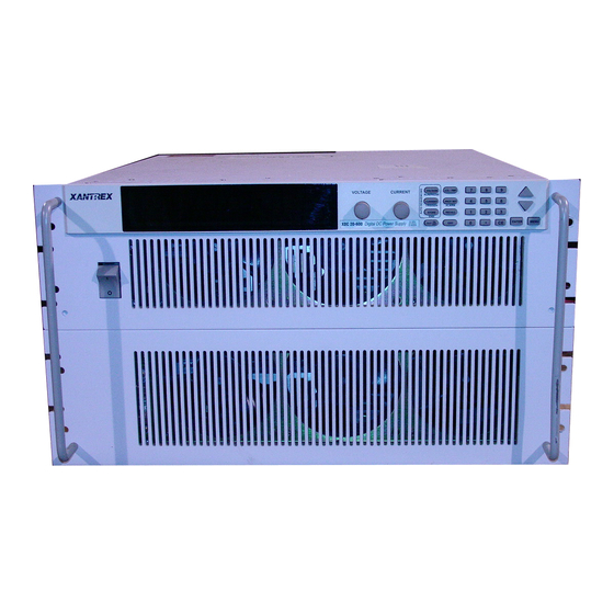
About The XDC Power Supply Front Panel Figure 1.2 Front Panel (12000 Watt) 1. Rack mount brackets 2. Handles 3. On/Off switch 4. Air intake vents 5. Front panel display (vacuum fluorescent display). See Figure 1.4 for details. 6. Voltage knob 7. -
Page 27: Figure 1.3 Keypad
About The XDC Power Supply Front Panel Figure 1.3 Keypad 1. Voltage knob: Turn knob to increase or decrease output voltage. (This is a velocity- sensitive rotary encoder.) 2. Current knob: Turn knob to increase or decrease output current limit. (This is a velocity-sensitive rotary encoder.) Note The secondary functions for keys 3 to 5 listed below operate when the power supply is in Auto Sequence mode. - Page 28 About The XDC Power Supply Front Panel 8. PROTECTION SET key: View and set protection setpoints. ALARM response: Read and clear alarm messages. ALARM annunciator indicates if there are any alarm messages. 9. RECALL settings key: Apply stored power supply settings. 10.
-
Page 29: Table 1.1 Front Panel Functions
About The XDC Power Supply Front Panel Table 1.1 Front Panel Functions Key Functions Voltage Setpoint Enter voltage Current Setpoint Enter current Output ON/OFF Toggle Local/Remote Mode Toggle Protection Set OVP level Enter OV level UVP level Enter UV level S/D if tripped? Select Y or N OCP level... - Page 30 About The XDC Power Supply Front Panel Menu Function ERROR MSGS Read error msgs USER LINES Aux line A Configure aux line A Set aux line A polarity Aux line B Configure aux line A Set aux line B polarity PON CONFIG Factory default Set output on/off...
-
Page 31: Display
About The XDC Power Supply Display MODEL INFO View info Display Figure 1.4 Front Panel Display 1. Main Display: Shows setpoints, readback, and menus. There are 14 characters. Each character is 5 pixels wide by 7 pixels high. 2. Status Annunciators: See “Status Annunciators” on page 28 and Figure 1.5 for detailed information. - Page 32 About The XDC Power Supply Status Annunciators 1. AUX A: Condition selected for auxiliary line A is TRUE. 2. Master: Power supply is selected to be the master in current share configurations. 3. AUX B: Condition selected for auxiliary line B is TRUE. 4.
-
Page 33: Rear Panel
About The XDC Power Supply Rear Panel Rear Panel Figure 1.6 Rear Panel (6000 Watt low and medium output shown) 1. Fan Exhaust Vents: Do not obstruct. 2. Remote Sensing Ports: From the rear point of view, left is negative; right is positive. -
Page 34: Overview Of Operation
About The XDC Power Supply Overview of Operation Overview of Operation Power ON Power ON describes the period between the time the AC power is turned ON and the time the power supply is ready for normal operation. Each supply comes with a series of factory default settings that may be in effect at the conclusion of the Power ON period. - Page 35 About The XDC Power Supply Overview of Operation Operating Manual for XDC Series Power Supply Artisan Technology Group - Quality Instrumentation ... Guaranteed | (888) 88-SOURCE | www.artisantg.com...
-
Page 36: Section 2. Installation
Section 2. Installation Overview Section 2 provides recommendations and procedures for inspecting, installing, and testing the power supply. For more information about controls and connectors, refer to the front panel diagrams (Figure 1.1 to Figure 1.5) as well as the rear panel diagram (Figure 1.6) in Section 1. -
Page 37: Inspection, Cleaning, And Packaging
Installation Inspection, Cleaning, and Packaging Inspection, Cleaning, and Packaging Initial When you receive your power supply, do a quick visual check. Inspection 1. Ensure that the box contains the power supply, the operating manual, the AC input cover and strain relief, and the output cover. 2. -
Page 38: Returning Power Supplies To The Manufacturer
Returning Power Supplies to the Manufacturer Returning Power Supplies to the Manufacturer Return Before returning a product directly to Xantrex you must obtain a Return Material Authorization (RMA) number and the correct factory “Ship To” address. Products Material must also be shipped prepaid. Product shipments will be refused and returned at your... -
Page 39: Packaging For Shipping Or Storage
Installation Returning Power Supplies to the Manufacturer Packaging for Follow these instructions to prepare the power supply for shipping or storage. Shipping or 1. When returning the unit or sending it to the service center, attach a tag to the unit Storage stating its model number (located on the front panel label) and serial number (located on the rear panel label). -
Page 40: Location, Mounting, And Ventilation
Installation Location, Mounting, and Ventilation Location, Mounting, and Ventilation Use the power supply in rack-mounted applications only. The power supply is designed to fit in a standard 19 in. (483mm) equipment rack. Rack Mounting WARNING- High Energy and High Voltage Ensure that the 8-32 rack mounting screws do not extend more than 1/8 in. -
Page 41: Figure 2.2 Unpacking The Power Supply (6000 Watt Shown)
Installation Location, Mounting, and Ventilation Figure 2.2 Unpacking the Power Supply (6000 Watt shown) Operating Manual for XDC Series Power Supply Artisan Technology Group - Quality Instrumentation ... Guaranteed | (888) 88-SOURCE | www.artisantg.com... -
Page 42: Ventilation
Installation Location, Mounting, and Ventilation Figure 2.3 Mounting the Power Supply in the Rack With Support Rails (6000 W shown) Ventilation Allow cooling air to reach the ventilation inlets on the front of the unit and allow 4 in. (10 cm) of unrestricted air space at the rear of the unit for the fan exhaust. Ventilation inlets are located on the top and sides;... -
Page 43: Ac Input Power
Installation AC Input Power AC Input Power WARNING Disconnect AC power from the unit before removing the connector cover. Live line voltages may be exposed when the cover is removed. WARNING A safety ground wire must be connected to the unit as shown in Figure 2.4 and Figure 2.6 to ensure operator safety. -
Page 44: Ac Input Wire
Installation AC Input Power AC Input Wire The manufacturer recommends the AC input wire specified in Table 2.2 and Table 2.3. This must be permanently connected to an approved AC distribution box with suitably rated over-current protection. If you require a special cord, contact the manufacturer. -
Page 45: Figure 2.5 Attaching The Ac Input Wires For 6000 Watt Units
Installation AC Input Power 6. Route the AC wires to the input terminal block by connecting the red, black, and white wires to the remaining 3 cable clamp connectors. There is no set order for connecting the wires. Any of the 3-phase wires can be connected to any of the 3 line input connectors. -
Page 46: Ac Wire Input Connection For 12000 W
Installation AC Input Power AC Wire Input See Figure 2.6, on page 44. Connection To connect the 12000 W AC input wires: for 12000 W 1. Ensure that the AC input cord is de-energized, and that the power switch on the front of the power supply is OFF. -
Page 47: Figure 2.6 Attaching The Ac Input Wires For 12000 Watt Units
Installation AC Input Power left terminal: Ground Connection 3 right terminals: 3-Phase Terminal Block Connectors AC input cover plate Figure 2.6 Attaching the AC Input Wires for 12000 Watt units Operating Manual for XDC Series Power Supply Artisan Technology Group - Quality Instrumentation ... Guaranteed | (888) 88-SOURCE | www.artisantg.com... -
Page 48: Basic Checks Or Self-Tests
Installation Basic Checks or Self-Tests Basic Checks or Self-Tests WARNING The factory setting for Power ON is 0V and 0A with the output OFF. These settings can be customized by end users. If you suspect that the power supply has been used by someone else since it was received from the factory, be prepared for the unit to power ON with a live DC output. -
Page 49: Power On Check
Installation Basic Checks or Self-Tests Power ON To complete the power on check: Check 1. Ensure that the AC power switch is OFF. 2. Connect the unit to an AC outlet. 3. Turn the front panel AC power switch to ON. After a short power-on delay, the front panel digital meters and the CV annunciator illuminate. -
Page 50: Current Mode Operation Check
Installation Basic Checks or Self-Tests 4. Slowly turn the Current knob clockwise 1 or 2 turns. Slowly turn the Voltage knob clockwise and observe both the front panel voltmeter and the DVM. Do not exceed 10V. 5. Compare the DVM reading with the front panel voltmeter reading to verify the accuracy of the internal voltmeter. -
Page 51: Load Wiring
Installation Load Wiring Load Wiring When connecting load wiring to the power supply, consider the following factors: • Current carrying capacity of the wire • Maximum load wiring length for operation with sense lines • Noise and impedance effects of the load lines Current As a minimum, load wiring must have a constant capacity greater than the output Carrying... -
Page 52: Load Wiring Length For Operation With Sense Lines
Installation Load Wiring Load Wiring For applications using remote sensing, or for improved voltage regulation at the load, you must limit the voltage drop across each load line. We recommend that you use Length for the larger load wiring to ensure a smaller voltage drop (1V maximum), although Operation units will compensate for up to 5V drop in each line with the remote sense lines with Sense... -
Page 53: Load Connections
Installation Load Connections Load Connections WARNING Exercise caution when operating the power supply. High energy levels can be stored at the output terminals on a power supply in normal operation. In addition, potentially lethal voltages exist in the power circuit and on the output and sense connectors of a power supply with a rated output greater than 40V. -
Page 54: Single Load
Installation Load Connections Single Load To connect a single load to the DC output bus bars (10–150V outputs): 1. Ensure that the power supply is powered OFF. 2. Place a bolt in the connecting hole of the negative bus bar, and fasten the negative wire or bus bar, a washer, and a nut to the bolt. -
Page 55: Multiple Loads
Installation Load Connections Multiple To connect multiple loads in parallel: Loads • Follow the “Single Load” procedure with the following exception: • To minimize interaction between loads, bring the wiring for each load directly back to the supply output. When each load to the power supply is wired separately, the loads will see only the precisely regulated output from the supply. -
Page 56: Output Strain Relief/Cover
Installation Load Connections Output Strain See Figure 2.8 and Figure 2.9 for installation of the output cover. Use this cover to protect users from accidental contact with the bus bars and to clamp output cables in Relief/Cover place. Figure 2.8 Output Bus Bar Cover for 6000 Watt units (Low and Medium Voltage) Figure 2.9 Output for 12000 Watt units (Low and Medium Voltage) Release 3.0... -
Page 57: Figure 2.10 Output Cover With Strain Relief For 6000 Watt Units
Installation Load Connections Figure 2.10Output Cover with Strain Relief for 6000 Watt units (High Voltage 300–600V) Operating Manual for XDC Series Power Supply Artisan Technology Group - Quality Instrumentation ... Guaranteed | (888) 88-SOURCE | www.artisantg.com... - Page 58 Installation Load Connections Figure 2.11 Output for 12000 Watt units (High Voltage 300–600V) Release 3.0 Artisan Technology Group - Quality Instrumentation ... Guaranteed | (888) 88-SOURCE | www.artisantg.com...
-
Page 59: Remote Sensing
Installation Remote Sensing Remote Sensing The power supply regulates the output voltage at the output connectors in its normal configuration without remote sense lines connected. Remote sensing lets the power supply track and regulate the output voltage at the load, and thereby compensate for the voltage drop in the load lines. The power supply will only compensate within the limitations of its voltage rating, to a maximum of 5V per load line. -
Page 60: Section 3. Operation
Section 3. Operation Overview Once you have installed the power supply and connected both the AC input power and the load as explained in Section 2, the power supply is in its default configuration and is ready to operate in local control mode. Section 3 begins by explaining how to power on and power off the power supply. -
Page 61: Powering Off The Power Supply
Operation Power Supply Operating States Powering From the front panel, the safest method for shutting down the power supply is: OFF the Step # Do This You Will See Power Supply The OUT OFF annunciator illuminates; Ouput V and I are 0. Switch the AC power to OFF. -
Page 62: Power Supply Regulation Modes
Operation Power Supply Regulation Modes Power Supply Regulation Modes The power supply has 3 regulation modes while in the Normal Operation State: • Constant Voltage (CV) • Constant Current (CC) • Constant Power (CP) The CV, CC, and CP annunciators indicate the regulation mode. Constant In this mode, the supply’s output voltage is constant while the current and power Voltage (CV) -
Page 63: Remote Control Modes
Operation Remote Control Modes Remote Control Modes A number of control interfaces are available. You can control the power supply remotely using 0–5V or 0–10V signals via the remote analog programming interface or from a remote terminal using a remote digital interface. A remote digital interface following RS-232 protocol is standard. -
Page 64: Front Panel Controls
Operation Front Panel Controls Front Panel Controls The power supply is shipped ready to operate in local mode. The factory default power-on setting is 0V, 0A with the DC output turned off. This section describes the function keys, menu options, and control knobs that you use to operate the power supply. -
Page 65: Menu Navigation
Operation Front Panel Controls 6. PROT SET: Lets you view and set protection setpoints. (See “Set Output Protection” on page 65.) 7. RECALL: Lets you apply stored power supply settings. (See “Recall Settings” on page 79.) 8. EXIT: Lets you cancel an operation or leave Calibration mode or Auto Sequence mode. -
Page 66: Control Knobs
Operation Front Panel Controls 11. KNOB LOCKOUT: Locks out either the Voltage or Current knob, or locks out both. (See “Lock Out Control Knobs” on page 98.) 12. SETPT LIMIT: Sets up minimum and maximum voltage, current, and power setpoints. (See “Set V, I, and P Limits” on page 100.) 13. -
Page 67: Power Supply Operation
Operation Power Supply Operation Power Supply Operation This section describes how to configure and operate the power supply. Set Voltage The VOLTAGE key allows you to set and view the DC voltage output setpoint. Step # Do This You Will See VOLTAGE Set #####V Use the numeric keypad, Voltage... -
Page 68: Set Power
Operation Power Supply Operation Set Power The POWER SETPOINT menu option lets you select the power output limit, measured in watts. The following table shows how to access and work with the Power Setpoint option. The power setpoint is normally at the maximum rating of the power supply, in the factory default configuration and does not need to be re-set for typical use. - Page 69 Operation Power Supply Operation OVP shuts down the power supply if the protection limit is exceeded. The other options offer a choice: they shut down the power supply or issue a warning. When the protection level is set to zero, that mechanism is considered disabled. However, in the case of OVP, a hardware protection mechanism still exists.
- Page 70 Operation Power Supply Operation To set the Over-Voltage Protection: Step # Do This You Will See PROT SET OVP SHUTDOWN ALARMS OVP SET 0V ENTER Use the Voltage knob, the numeric, OVP SET ####V keypad, or the arrow keys to enter a value.
- Page 71 Operation Power Supply Operation These 2 extra steps are shown in the following example. To set the Under-Voltage Protection: Step # Do This You Will See PROT SET OVP SET 0V ALARMS Press repeatedly until the UVP SET 0V PROT SET ALARMS desired setting appears.
- Page 72 Operation Power Supply Operation To set the Under-Current Protection: Step # Do This You Will See PROT SET OVP SET 0V ALARMS Press repeatedly until the PROT SET UCP SET 0A ALARMS desired setting appears. UCP SET 0A ENTER Use the Current knob, the numeric UCP SET ####A keypad, or the arrow keys to enter a value.
- Page 73 Operation Power Supply Operation To set the Under-Power Protection: Step # Do This You Will See PROT SET OVP SET 0V ALARMS Press repeatedly until the UPP SET 0W PROT SET ALARMS desired setting appears. UPP SET 0W ENTER Use both the Current and Voltage UPP SET ####W knobs, or the numeric keypad, or the arrow keys to enter a value (must be...
-
Page 74: Set Shutdown Recovery For Ac Off And Otp
Operation Power Supply Operation To set Fold Protection: Step # Do This You Will See PROT SET OVP SET 0V ALARMS Press repeatedly. PROT SET Fold SD Mode ALARMS ENTER Use the arrow keys or the numeric Fold on #### keypad to select the value: None, CC, CV, CP ENTER... -
Page 75: Respond To Alarms
Operation Power Supply Operation To set both OTP and AC Off to Auto-Recovery: Step # Do This You Will See ERROR MSGS MENU S/D RECOVERY 3 times OTP Latched ENTER OTP AutoRecov ACO AutoRecov ENTER OTP is set to Auto Recovery. ACO remains set to Auto Recovery ENTER and the display returns to its default... - Page 76 Operation Power Supply Operation If the alarms are cleared, the system returns to its default operating state. If the alarms persist, the system prompts OVP SET #####V. The system has shifted to output protection mode. You can press ENTER to work with the OVP setting or press the arrow keys to view the other protection settings.
-
Page 77: Set Up Remote Control
Operation Power Supply Operation Shutdown vs Protection Alarm If a protection setpoint is exceeded, the system does the following: 1. If S/D if tripped? Y has been selected, the unit shuts down. If it is an OVP alarm, the unit shuts down. 2. -
Page 78: Select Remote Control Source
Operation Power Supply Operation Select The REMOTE SELECT menu option allows you to select an interface for remote control. Before selecting a remote control source, be sure to set up each interface Remote using the Remote Configure menu. See “Configure Remote Control Source” on page Control Source Remote control sources are listed here along with their respective programming... -
Page 79: Configure Remote Control Source
Operation Power Supply Operation Configure The REMOTE CONFIG menu option lets you set up the attributes of the remote control sources. Remote Control The following table shows how to access and work with the Remote Configuration Source option. Step # Do This You Will See ERROR MSGS MENU... -
Page 80: Store User Settings
Operation Power Supply Operation Store User If you have a frequent or constant need for a specific voltage and current output, you can save these setpoints in the power supply’s memory as a user setting. Once a Settings setting is stored, it remains in the power supply’s memory after the unit is powered off. -
Page 81: Change Stored Settings
Operation Power Supply Operation The following table demonstrates how to set and save current and voltage settings: Step # Do This You Will See Set #####V VOLTAGE Turn the Voltage knob or use the Set #####V numeric keypad to enter a voltage Your voltage setting appears on the setpoint. -
Page 82: Recall Settings
Operation Power Supply Operation Recall After you have saved one or more settings, you can press RECALL to retrieve them from the power supply’s non-volatile memory or to run an auto-sequence program. Settings (You can also recall stored settings through your Power ON configuration. See “Configure Power ON Settings”... - Page 83 Operation Power Supply Operation To select a stored user setting: Step # Do This You Will See Press twice. User Setting RECALL User Set ## ENTER Use the numeric keypad or arrow keys to enter a value between 1 and 10. Use the numeric keypad ENTER or arrow keys to enter a value...
-
Page 84: Table 3.1 Settings Affected By Recall
Operation Power Supply Operation Table 3.1 Settings Affected by Recall Feature Factory Preset Value Voltage setpoint 0.0V Current setpoint 0.0A Power setpoint 103% of power rating Triggered voltage setpoint Disabled (DEF) Triggered current setpoint Disabled (DEF) Triggered power setpoint Disabled (DEF) Trigger source None Low voltage setpoint limit... -
Page 85: Read Error Messages
Operation Power Supply Operation Read Error The ERROR MSGS menu option lets you display up to 50 queued messages. Once each message has been read, it is cleared from the system. Press either arrow key to Messages clear the displayed message and bring up the next message. Once all messages have been read and cleared, the prompt reads No errors, and the power supply automatically returns to the default state. -
Page 86: Configure User Lines
Operation Power Supply Operation Configure The USER LINES menu option lets you configure the auxiliary status lines User Lines The Auxiliary (Aux) lines are 2 open collector outputs that can be used to monitor the status of the power supply. The auxiliary lines are referred to as AUX A and AUX B. -
Page 87: Configure Power On Settings
Operation Power Supply Operation Aux line B has been selected to be configured. To configure Aux line B: Step # Do This You Will See Press repeatedly until the Cfg CV desired option appears. For this example, CV is selected. Pol Act High ENTER Press repeatedly until the... - Page 88 Operation Power Supply Operation Factory Preset Selecting Factory Preset lets you restore the factory defaults the next time the power supply is powered ON. To select Factory Preset: Step # Do This You Will See ERROR MSGS MENU 2 times PON CONFIG MENU Last Setting...
- Page 89 Operation Power Supply Operation User Setting User Setting lets you restore a custom setting the next time the unit is powered on. This assumes at least one user setting has been stored in memory. See “Store User Settings” on page 77. To select User Setting: Step # Do This You Will See...
-
Page 90: Program Auto Sequence
Operation Power Supply Operation Auto-Sequence Auto Sequence lets you recall a stored program next time the unit is powered on. (Assumes at least one program has been saved in memory. See “To edit the sequence’s trigger source:Using Auto Sequencing” on page 96.) To select Auto Sequence: Step # Do This You Will See... -
Page 91: Programming A Sequence
Operation Power Supply Operation Programming This option allows you to set up command programs for automated operation. a Sequence To program a sequence: Note In the following procedure, only change the default setpoints if required. Otherwise simply press to accept. ENTER Step # Do This You Will See... - Page 92 Operation Power Supply Operation Step # Do This You Will See Set the step advance method. To Next Step To go to the next step in Step 2 ENTER the sequence. This will return you to step 7 in this table. Repeat steps 7 to 14 for all remaining steps in the sequence.
- Page 93 Operation Power Supply Operation Setting step advance by trigger: This procedure continues from step 13 in the “To program a sequence:” table. It explains how to program the sequence to advance a particular step by waiting for a certain trigger event. See “Editing Trigger Source of a Sequence” on page 96 for more information about trigger event.
-
Page 94: Deleting A Sequence
Operation Power Supply Operation Deleting a This option allows you to delete an entire sequence. Sequence To delete a sequence: Step # Do This You Will See ERROR MSGS MENU 6 times or AUTO SEQ PGM MENU Sequence 1 ENTER . -
Page 95: Editing A Sequence Step
Operation Power Supply Operation Editing a This option allows you to edit a particular step in a sequence that has already been programmed or to add steps to a new program. Sequence Step To edit a step in a programmed sequence: Step # Do This You Will See ERROR MSGS... -
Page 96: Inserting A Sequence Step
Operation Power Supply Operation Inserting a This option allows you to insert a particular step in a sequence that has already been programmed. Sequence Step To insert a step into a programmed sequence: Step # Do This You Will See ERROR MSGS MENU 6 times or... -
Page 97: Deleting A Sequence Step
Operation Power Supply Operation Deleting a This option allows you to delete a particular step in a sequence that has already been programmed. Sequence Step To delete a step in a programmed sequence: Step # Do This You Will See ERROR MSGS MENU 6 times or... -
Page 98: Editing Repeat Times Of A Sequence
Operation Power Supply Operation Editing This option allows you to edit the number of times the sequence will run before it goes into STOP mode. Repeat Times of a To edit the sequence’s repeat times: Sequence Step # Do This You Will See ERROR MSGS MENU... -
Page 99: Editing Trigger Source Of A Sequence
Operation Power Supply Operation Editing When steps are programmed to advance step by trigger, this option allows you to edit the source of those trigger events. Trigger Source of a To edit the sequence’s trigger source:Using Auto Sequencing Sequence Step # Do This You Will See ERROR MSGS MENU... -
Page 100: Using Auto Sequencing
Operation Power Supply Operation Using Auto Auto Sequence programs can be set to run as a Power ON default or recalled from memory by pressing the RECALL key. In Auto Sequence mode, 3 of the function Sequencing keys operate as alternates: •... -
Page 101: Configure Display
Operation Power Supply Operation Configure The DISPLAY CONFIG menu option allows you to select the readback values displayed when the power supply is operating in its default state. Display The factory default is to display voltage and current readback, but you can also choose voltage and power, current and power, or voltage, current, and power. - Page 102 Operation Power Supply Operation If you attempt to use either knob, the display shows Knobs Locked, and there is no effect on the output. To lock out only the Voltage knob: Step # Do This You Will See ERROR MSGS MENU until you see the “KNOB KNOB LOCKOUT...
-
Page 103: Set V, I, And P Limits
Operation Power Supply Operation Set V, I, and P The voltage, current and power setpoints can be limited to less than the supply rating range to match the tolerance of connected equipment or any other criteria you may Limits have. You can control the voltage, current and power setpoint limits through the SETPT LIMIT menu option. - Page 104 Operation Power Supply Operation To set the current limits: Step # Do This You Will See ERROR MSGS MENU until you see the “SETPT SETPT LIMIT LIMIT” option Voltage Limit ENTER Current Limit High 0A ENTER Use the Current knob, arrow keys, or High #####A numeric keypad to enter a value.
-
Page 105: Slew Rate
Operation Power Supply Operation To set the power limit: Step # Do This You Will See ERROR MSGS MENU until you see the “SETPT SETPT LIMIT LIMIT” option Voltage Limit ENTER 2 times Power Limit High #####W ENTER Use the Voltage and Current knobs, High #####W arrow keys, or numeric keypad to enter a value. - Page 106 Operation Power Supply Operation The slew rate error increases as the slew rate increases. Selecting SLEW RATE from the main menu will give you two choices: Voltage slew - adjust the voltage slew rate Voltage default - restore the default voltage slew rate Selecting VOLTAGE DEFAULT will return the slew rate to the default value of 1% rated voltage per 150us.
-
Page 107: View Model Information
Default Display View Model The MODEL INFO menu option displays hardware and software information including: Information • Manufacturer (Xantrex) • Model description (e.g. XDC 60–100) • Voltage and current ratings (60 V 100 A) • ROM version (e.g. ROM Ver. 5.000) •... -
Page 108: Section 4. Remote Operation
Section 4. Remote Operation Overview This chapter is divided into 3 main parts: • “Remote Analog Operation” on page 108 provides an overview of how to use remote analog control • “Multichannel Operation (6000 Watt only)” on page 113 gives information on the setup and use of Multichannel functionality •... - Page 109 Remote Operation Overview The IEEE 488.2 common commands that are supported are: *CLS *PSC <on_off_state> *ESE *RCL <user_setting> *ESE <enable_mask> *RST *ESR? *SAV <user_setting> *IDN? *SDS *OPC *SRE? *OPC? *SRE <enable_mask> *OPT *STB *PRE? *TRG *PRE <enable_mask> *TST? *PSC? *WAI For a detailed listing of all SCPI commands, see Appendix B, Table B.1 to Table B.14.
-
Page 110: Making Connections For Remote Control
Remote Operation Making Connections for Remote Control Making Connections for Remote Control See Figure 4.1 for the locations of the RS-232, GPIB and CANbus connectors and the locations and the pin numbers of the User Lines and the Analog Programming Lines. -
Page 111: Remote Analog Operation
Remote Operation Remote Analog Operation Remote Analog Operation Analog The analog interface has 2 ports: the user lines and the analog programming lines. Connections The tables below show the function and power flow for each pin on these ports. The user lines are optically isolated. The output lines are open collector configuration. -
Page 112: Table 4.2 Analog Programming Pins
Remote Operation Remote Analog Operation CHASSIS POTENTIAL ISOLATED USER LINES CNY17-2 USER LINES CNY17-2 508 Ohm 0.4W CNY17-2 508 Ohm 0.4W CNY17-2 Vf = 1.3V TYP, 1.5V MAX If = 10mA Recommended, 90mA MAX Figure 4.2 Schematic For User Line Interface Table 4.2 Analog Programming Pins Pin # Function... -
Page 113: Configure Analog Control
Remote Operation Remote Analog Operation Table 4.3 Analog Pin Connections for Power Loop Back Programming Line Pin # User Line Pin # Remote Interlock Using a Contact Closure The interlock input may be configured for use with an external voltage free contact. Connect pins as shown: Table 4.4 Analog Pin Connections with a Contact Closure Programming Line Pin #... - Page 114 Remote Operation Remote Analog Operation Next select analog programming as the remote control interface. Your options are • Analog V & I - voltage and current programmed via the analog interface • Analog V - voltage programmed via the analog interface; current set via front panel •...
-
Page 115: Using Remote Analog Control
Remote Operation Remote Analog Operation Using Connect your programming voltage sources and monitors, ensuring that the appropriate 0– 5V or 0–10V range has been configured and selected. (See page 75.) Remote With the Analog Control mode selected, varying the programming source from 0 to Analog 5V (or 10) will vary the output voltage or current from 0 to its rated maximum. -
Page 116: Multichannel Operation (6000 Watt Only)
Remote Operation Multichannel Operation (6000 Watt only) Multichannel Operation (6000 Watt only) Multichannel Multichannel operation is only available for 6000 Watt units. You may remotely Connections control up to 50 power supplies from one programming interface (RS-232 or GPIB) by using multichannel addressing if the CANbus option is installed. One power supply will be connected to a PC via RS-232 or GPIB. -
Page 117: Configuration
Remote Operation Multichannel Operation (6000 Watt only) Configuration Before connecting a power supply to a multichannel network, you must configure each power supply with a unique address. The front panel or a remote interface maybe used to do this. One power supply must be configured to operate via RS-232 or GPIB. Front Panel 1. -
Page 118: Using Multichannel Operation
Remote Operation Multichannel Operation (6000 Watt only) 2. At least one power supply should be connected to a PC via RS-232 or GPIB for multichannel functionality. Configure each of the power supplies with a unique address, as described in the configuration section. Addresses may be in the range 1 to 50 inclusive. -
Page 119: Multichannel Commands
Remote Operation Multichannel Operation (6000 Watt only) Note that slave units have an automatic readdressing capability when in multchannel mode. A slave unit will attempt another address when it is added to a string with an address that is already taken. If no new address can be found then the following error will be queued: Error 1702, “Multichannel address taken”... -
Page 120: Multichannel Broadcast Commands
Remote Operation Multichannel Operation (6000 Watt only) Multichannel Add a suffix of "0" to simultaneously broadcast the "command" to the master and all other units on the CANbus. Only commands are allowed, queries are not allowed. Broadcast Note that there will be a lag in execution time between the local unit and all other Commands units of up to a maximum of 20 ms. -
Page 121: Rs-232 Operation
Remote Operation RS-232 Operation RS-232 Operation RS-232 Use a standard null modem cable to connect the power supply to the host interface. Connection The RS-232 port is a standard male DB9 connector. Table 4.6 describes the pin functions. Pins 1, 4, 6, and 9 are not used. Table 4.6 RS-232 Pins Pin # Function... -
Page 122: Using Rs-232
Remote Operation RS-232 Operation Next, select RS-232 as the remote control interface. Step # Do This You Will See ERROR MSGS MENU 4 times REMOTE SELECT RS-232 ENTER RS-232 setting is saved. ENTER Press the LCL/RMT button to begin remote operation via the RS-232 interface. SCPI Set the band rate: SYST:COMM:SER:BAUD {1200 | 2400 | 4800 | 9600 | 19200 |... -
Page 123: Gpib Operation
Remote Operation GPIB Operation GPIB Operation GPIB The GPIB port is a special GPIB female connector. Table 4.7 describes the pin Connection functions. Pin 12 is not used. Table 4.7 GPIB Pins Pin # Function NRFD NDAC Not used Ground Ground Ground Ground... -
Page 124: Configuration
Remote Operation GPIB Operation Configuration Configure the power supply’s GPIB address and power-on service request setting. The defaults are GPIB address 2 and power-on service request off. Front panel First set the GPIB parameters: Step # Do This You Will See ERROR MSGS MENU 5 times... -
Page 125: Using Gpib
Remote Operation GPIB Operation SCPI To set up GPIB control parameters: SYST:COMM:GPIB:ADDR <GPIB-address> where • the GPIB address may be in the range 1 to 30. To configure the unit to generate a power-on service request: SYST:COMM:GPIB:PONS {ON | OFF} To select GPIB as the remote control source: SYST:REM:SOUR GPIB Using GPIB Sending a GPIB command should put the power supply in remote mode with the... -
Page 126: Store User Settings
Remote Operation SCPI Commands for Digital Interfaces SCPI Commands for Digital Interfaces These SCPI commands are for use with GPIB, RS-232 and Multichannel remote digital interfaces. Set Up Power For a complete list of commands and remote functionality, see Appendix B, “SCPI ON Defaults Command Reference”. - Page 127 Remote Operation SCPI Commands for Digital Interfaces Last Setting Selecting Last Setting lets you restore the settings that are in use when the power supply is powered off, the next time it is powered on. To power on the last stored setting: OUTP:PON:REC LAST To check the current user setting: OUTP:PON:REC?
-
Page 128: Power On Output State
Remote Operation SCPI Commands for Digital Interfaces Power On You may also change the output state whether the output is enabled or disabled at power on. Output State To change the power on at output state: OUTP:PON:STAT [ON|OFF|1|0] To check the setting: OUTP:PON:STAT? Reset Resetting the unit puts certain features to a known state. -
Page 129: Table 4.8 Features Affected By Reset (*Rst) Command
Remote Operation SCPI Commands for Digital Interfaces Table 4.8 Features Affected by Reset (*RST) Command Feature Reset State (*RST) Voltage setpoint 0.0V Current setpnoint 0.0A Power setpoint 103% of power rating Low voltage setpoint limit 0.0V High voltage setpoint limit 103% of voltage rating Low current setpoint limit 0.0A High current setpoint limit 103% of current rating... -
Page 130: Store User Settings
Remote Operation SCPI Commands for Digital Interfaces Store User If you have a frequent or constant need for a specific voltage and current output, you can save these setpoints in the power supply’s memory as a user setting. Once a Settings setting is stored, it remains in the power supply’s memory after the unit is powered off. -
Page 131: Change Remote/Local Control Of Power Supply
Remote Operation SCPI Commands for Digital Interfaces Change A SCPI command is provided for use with the RS-232 and multichannel interfaces to change the remote/local mode. (GPIB will use IEEE 4888-1 functions to change Remote/Local modes.) Control of Power Supply SYST:REM:STAT {LOC|REM|RWL} Where: •... - Page 132 Remote Operation SCPI Commands for Digital Interfaces To check a triggered setpoint: SOUR:VOLT:TRIG? SOUR:CURR:TRIG? SOUR:POW:TRIG? To set limits: SOUR:VOLT:LIM:HIGH <voltage> SOUR:VOLT:LIM:LOW <voltage> SOUR:CURR:LIM:HIGH <current> SOUR:CURR:LIM:LOW <current> SOUR:POW:LIM:HIGH <power> SOUR:POW:LIM:LOW <power> If the high end of the range was set to 5 volts, the command, SOUR:VOLT 10 would return an error.
-
Page 133: Configure V, I, P Protection Limits
Remote Operation SCPI Commands for Digital Interfaces Configure V, I, Over-Voltage Protection P Protection To set the Over-Voltage Protection level: Limits SOUR:VOLT:PROT <voltage> To check the Over-Voltage Protection level: SOUR:VOLT:PROT? To check if the Over-Voltage Protection was tripped: SOUR:VOLT:PROT TRIP? Alternatively, you can query the status registers. - Page 134 Remote Operation SCPI Commands for Digital Interfaces Under-Current Protection To set the Under-Current Protection level: SOUR:CURR:PROT:UND <current> SOUR:CURR:PROT:UND:STAT <on-off-state> The first UCP protection command sets the protection level. The second command lets you choose a warning alarm only [OFF] or shut down with an alarm [ON] if the protection level is exceeded.
-
Page 135: Configure Other Protection Mechanisms
Remote Operation SCPI Commands for Digital Interfaces Configure Fold Protection Other Fold protection causes the supply to shut down if the selected regulation mode is Protection entered. A delay time may be specified as well. Mechanisms To set the fold mode: OUTP:PROT:FOLD {CC|CV|CP|NONE} Where: NONE indicates fold protection is disabled. - Page 136 Remote Operation SCPI Commands for Digital Interfaces Over Temperature Protection The user has the option of setting whether the over temperature protection (OTP) mechanism is latched or automatically resumes operation. (The trip levels are internally set and cannot be changed by the user.) SENSE:TEMP:PROT:LATCH {ON|1|OFF|0} Where: ON or 1 means the supply will be latched in shutdown if OTP is tripped, until the...
-
Page 137: Clear Protection Event
Remote Operation SCPI Commands for Digital Interfaces Clear To clear a protection mechanism that has tripped: Protection OUTP:PROT:CLE Event This will clear all protection mechanisms and re-enable the output. If the condition that caused the alarm still exists, the protection will be allowed to trip again. View Power The following 3 commands query the voltage, current, or power being supplied at the output terminals. -
Page 138: Read Error Messages
Remote Operation SCPI Commands for Digital Interfaces To check the setting: OUTP:AUXA:SOUR? To set up Auxiliary line B: OUTP:AUXB:SOUR <aux-line-mnemonic> To set the polarity of the auxiliary status lines: OUTP:AUXA:POL {HIGH|LOW} OUTP:AUXB:POL {HIGH|LOW} Where: HIGH means that the logic of the output is active high. (That is, if the condition is true, the line is pulled high.) LOW means the logic of the output is active low. -
Page 139: Triggering Commands
Remote Operation SCPI Commands for Digital Interfaces Triggering Triggers are event-driven signals that instruct power supplies to change their output. Triggering provides a method to control changes in the power supply’s output and to Commands program several power supplies to react at the same time. Triggering is useful in manufacturing processes where power requirements change as the machinery performs different operations. - Page 140 Remote Operation SCPI Commands for Digital Interfaces Operation Users can select and start a sequence, and while the sequence is running, pause or end it. Users can press and hold the TRIGGER button to skip over steps that have a set duration.
-
Page 141: Programming Sequences
Remote Operation SCPI Commands for Digital Interfaces Programming Select Sequence to Program Sequences PROGram:NAME <sequence_number> <sequence_number> is a number between 1 and 10 that corresponds to the number of the sequence. Define the name of the program to be selected. If <sequence_number> already exists, then that existing program is selected. - Page 142 Remote Operation SCPI Commands for Digital Interfaces Selecting a Trigger Source If any triggers are programmed into the sequence, select a trigger source: PROG:TRIG:SOUR {BUS|MAN|EXT|IMM} • BUS - trigger signal is IEEE 488.1 GET or *TRG • MANual - trigger input is from the front panel TRIGGER key •...
-
Page 143: Auto Sequence Operation
Remote Operation SCPI Commands for Digital Interfaces Auto Select Sequence to Run Sequence PROGram:NAME <sequence_number> Operation where <sequence_number> can range from 1 to 10. Operation Running PROGram :STATe [RUN|PAUSe|STOP] • Once the programmed sequence has been selected, you can start it by setting the state to RUN, by sending the command PROG:STAT RUN. -
Page 144: Slew Rate
Remote Operation SCPI Commands for Digital Interfaces Slew Rate The slew rate is calculated as a function of change in the output voltage and a given time interval. The maximum slew rate is 1% V rating/150us. The slew rate is saved upon power off and restored at power on. -
Page 145: Identification Query
SCPI Commands for Digital Interfaces Identification The identification query command returns a string that states the manufacturer, model, serial number, and firmware revision. Query *IDN? may return “Xantrex, XDC 60-100, 100000, 3.000/0/0/0000. Option *OPT? Identification Query SYST[<channel>]:OPTion? The option identification query returns a string listing any reportable options that are installed in the power supply. - Page 146 Remote Operation SCPI Commands for Digital Interfaces Enable Register The enable register enables reporting of the event bits to the summary bit or the status byte. The contents of the enable register are unchanged by *CLS and *RST. Transition Filters A positive transition filter allows an event to be reported when a condition changes from false to true.
-
Page 147: Figure 4.4 Operation Status Registers
Remote Operation SCPI Commands for Digital Interfaces STATus:OPERation:REGulating Not Used Not Used Not Used Not Used Not Used Not Used Not Used Over VOLtage Not Used Under VOLTage Not Used Over CURrent Not Used Under CURrent Not Used Over POWer Not Used Under POWer Not Used... -
Page 148: Table 4.9 Operation Status Register
Remote Operation SCPI Commands for Digital Interfaces Table 4.9 OPERation Status Register Bit Weight Bit Name Description CALibrating Indicates that the supply is in CALibration Mode. SETTling Not implemented RANGing Not implemented SWEeping Not implemented MEASuring Not implemented Waiting for TRIGger Indicates if the supply is waiting Summary for a TRIGger. -
Page 149: Table 4.10 Regulating Sub-Register
Remote Operation SCPI Commands for Digital Interfaces REGulating Sub-Register This describes the regulating mode. If none of these bits is active, the output unregulated (UNRegulated) bit is active in the questionable status register. Table 4.10 REGulating Sub-Register Bit Weight Bit Name Description The power supply is regulating in Constant Voltage mode. -
Page 150: Table 4.12 Protection Shutdown Sub-Register
Remote Operation SCPI Commands for Digital Interfaces Protection SHUTdown Sub-Register Table 4.12 Protection SHUTdown Sub-Register Bit Weight Bit Name Description Over VOLTage Over voltage protection has tripped Under VOLTage Under voltage protection has tripped Over CURrent Over current protection has tripped Under CURrent Under current protection has tripped Over POWer... -
Page 151: Table 4.13 Remote Control Sub-Register
Remote Operation SCPI Commands for Digital Interfaces Table 4.13 Remote CONtrol Sub-Register Bit Weight Bit Name Description Analog The Voltage Setpoint is under control of the Control Analog Programming Interface. Voltage Analog The Current Setpoint is under control of the Control Analog Programming interface. - Page 152 Remote Operation SCPI Commands for Digital Interfaces QUEStionable Status Register The Questionable Status Register is a 16-bit register that stores information about questionable events or status during power supply operation. That is, bits in these registers may indicate that the output of the supply is of undesirable or questionable quality.
-
Page 153: Figure 4.5 Questionable Status Registers
Remote Operation SCPI Commands for Digital Interfaces Over VOLtage STATus:QUEStionable:VOLTage Under VOLtage Not Used Not Used Not Used Not Used Not Used Not Used Not Used Not Used Not Used Not Used Not Used Not Used Not Used Not Used Over CURrent STATus:QUEStionable:CURRent Under CURrent... -
Page 154: Table 4.15 Questionable Status Register
Remote Operation SCPI Commands for Digital Interfaces Table 4.15 QUEStionable Status Register Bit Weight Bit Name Description VOLTage Summary Reflects a summary of the VOLTage Sub-Register. CURRent Summary Reflects a summary of the CURRent Sub-Register. TIME Not implemented POWer Summary Reflects a summary of the POWer Sub-Register. -
Page 155: Table 4.16 Voltage Sub-Register
Remote Operation SCPI Commands for Digital Interfaces VOLTage Sub-Register This shows whether the present voltage level is over or under the specified trip limit. Table 4.16 VOLTage Sub-Register Bit Weight Bit Name Description Over VOLtage Set if the supply’s output voltage exceeds the over-voltage trip level, either user-specified variable trip limit, or the fixed trip limit. -
Page 156: Table 4.19 Temperature Sub-Register
Remote Operation SCPI Commands for Digital Interfaces TEMPerature Sub-Register This shows whether the temperature of critical components is near or over the maximum operating temperature. Table 4.19 TEMPerature Sub-Register Bit Weight Bit Name Description Over TEMperature Set if the power supply temperature exceeds the maximum operating temperature. -
Page 157: Table 4.20 Standard Event Status Register
Remote Operation SCPI Commands for Digital Interfaces Table 4.20 Standard Event Status Register Bit Weight Bit Name Description Operation Set if KOPC command has been received Complete and all pending operations have been (OPC) completed. The message, Event –800 Operation Complete, is loaded into the Error/Event Queue. -
Page 158: Table 4.21 Status Byte Summary Register
Remote Operation SCPI Commands for Digital Interfaces Status Byte The Status byte register contains the STB and RQS(MSS) messages as defined in 488.1. The user can read the status byte register using a 488.1 serial poll or the 488.2 *STB? common command. If the user sends a serial poll, bit 6 will respond with Request Service (RSQ). - Page 159 Remote Operation SCPI Commands for Digital Interfaces Questionable Status Register Summary (QSR) This bit is TRUE when a bit in the Questionable Event Status Register is set and its corresponding bit in the Questionable Status Enable Register is TRUE. Message Available (MAV) This bit is TRUE whenever the power supply is ready to accept a request by the Digital Programming Interface to output data bytes.
-
Page 160: Status Register Commands
Remote Operation SCPI Commands for Digital Interfaces Status In the following sections <status-enable> is a value from 0 to 32767 representing a 15-bit register mask. Register Commands SCPI Status Commands Preset Status Configures the status data structures to ensure that certain events are reported at a higher level through the status-reporting mechanism. - Page 161 Remote Operation SCPI Commands for Digital Interfaces IEEE 488.2 Status and Event Commands Clear Status Command Clears all Event Registers, including the Status Byte, the Standard Event Status and the Error Queue. Command: *CLS SCPI equivalent for multichannel use: STATus[<channel>]:CLEar Standard Event Status Enable Register The Event Summary Enable command determines which bits in the Standard Event Status Register are summarized in the Event Summary Bit (ESB) of the Status Byte.
- Page 162 Remote Operation SCPI Commands for Digital Interfaces Service Request Enable Register The Service Request Enable Register allows the user to select the reasons for the power supply to issue a service request. The Service Request Enable Register allows the user to select which summary messages in the Status Byte Register may cause service requests.
- Page 163 Remote Operation SCPI Commands for Digital Interfaces Status Byte The status byte query will return the contents of the status byte register and the MSS (Master Summary Status) message. The response is in the format of a weighted decimal value representing the status byte register and the MSS message (bit 6). Thus, the response to *STB? is identical to the response to a serial poll except that the MSS message appears in bit 5 in place of the RQS message.
- Page 164 Remote Operation SCPI Commands for Digital Interfaces Wait-to-Continue Command The Wait-to-Continue command prevents the power supply from executing any further commands or queries until the no-operation-pending flag is TRUE. Command: *WAI Operation Status Register Commands Query Operation Status Register Event SCPI command: STATus[<channel>]:OPERation[:EVENt]? Query Operation Status Register Condition SCPI command: STATus[<channel>]:OPERation:CONDition?
- Page 165 Remote Operation SCPI Commands for Digital Interfaces Regulating Sub-Register Commands Query Regulating Event SCPI command: STATus[<channel>]:OPERation:REGulating[:EVENt]? Query Regulating Condition SCPI command: STATus[<channel>]:OPERation:REGulating:CONDition? Enable Regulating Sub-Register SCPI command: STATus[<channel>]:OPERation:REGulating:ENABle <status-enable> Query format: STATus[<channel>]:OPERation:REGulating:ENABle? Set Regulating Positive Transition Filter SCPI command: STATus[<channel>]:OPERation:REGulating:PTRansition <status-enable>...
- Page 166 Remote Operation SCPI Commands for Digital Interfaces Shutdown Sub-Register Commands Query Shutdown Event SCPI command: STATus[<channel>]:OPERation:SHUTdown[:EVENt]? Query Shutdown Condition SCPI command: STATus[<channel>]:OPERation:SHUTdown:CONDition? Enable Shutdown Sub-Register SCPI command: STATus[<channel>]:OPERation: SHUTdown:ENABle <status-enable> Query format: STATus[<channel>]:OPERation:SHUTdown:ENABle? Set Shutdown Positive Transition Filter SCPI command: STATus[<channel>]:OPERation:SHUTdown:PTRansition <status-enable>...
- Page 167 Remote Operation SCPI Commands for Digital Interfaces Protection Shutdown Sub-Register Commands Query Protection Shutdown Event SCPI command: STATus[<channel>]:OPERation:SHUTdown:PROTection[:EVENt] Query Protection Shutdown Condition SCPI command: STATus[<channel>]:OPERation:SHUTdown:PROTection:CONDiti Enable Protection Shutdown Sub-Register SCPI command: STATus[<channel>]:OPERation:SHUTdown:PROTection:ENABle <status-enable> Query format: STATus[<channel>]:OPERation:SHUTdown:PROTection:ENABle? Set Protection Shutdown Positive Transition Filter SCPI command: STATus[<channel>]:OPERation:SHUTdown:PROTection:PTRansi tion <status-enable>...
- Page 168 Remote Operation SCPI Commands for Digital Interfaces Remote Control Sub-Register Commands Query Remote Control Event SCPI command: STATus[<channel>]:OPERation:RCONtrol[:EVENt]? Query Remote Control Condition SCPI command: STATus[<channel>]:OPERation:RCONtrol:CONDition? Enable Remote Control Sub-Register SCPI command: STATus[<channel>]:OPERation:RCONtrol:ENABle <status-enable> Query Format: STATus[<channel>]:OPERation:RCONtrol:ENABle? Set Remote Control Positive Transition Filter SCPI command: STATus[<channel>]:OPERation:RCONtrol:PTRansition <status-enable>...
- Page 169 Remote Operation SCPI Commands for Digital Interfaces Current Share Sub-Register Commands Query Current Share Register Event STATus[<channel>]:OPERation:CSHare[:EVENt]? Query Current Share Register Condition SCPI command: STATus[<channel>]:OPERation:CSHare:CONDition? Enable Current Share Sub-Register SCPI command: STATus[<channel>]:OPERation:CSHare:ENABle <status-enable> Query Format: STATus[<channel>]:OPERation:CSHare:ENABle? Set Current Share Positive Transition Filter SCPI command: STATus[<channel>]:OPERation:CSHare:PTRansition <status-enable>...
- Page 170 Remote Operation SCPI Commands for Digital Interfaces Questionable Status Register Commands Query Questionable Status Register Event SCPI command: STATus[<channel>]:QUEStionable[:EVENt]? Query Questionable Status Register Condition SCPI command: STATus[<channel>]:QUEStionable:CONDition? Enable Questionable Status Register SCPI command: STATus[<channel>]:QUEStionable:ENABle <status-enable> Query Format: STATus[<channel>]:QUEStionable:ENABle? Set Questionable Status Positive Transition Filter SCPI command: STATus[<channel>]:QUEStionable:PTRansition <status-enable>...
- Page 171 Remote Operation SCPI Commands for Digital Interfaces Voltage Sub-Register Commands Query Voltage Sub-Register Event SCPI command: STATus[<channel>]:QUEStionable:VOLTage[:EVENt]? Query Voltage Sub-Register Condition SCPI command: STATus[<channel>]:QUEStionable:VOLTage:CONDition? Enable Voltage Sub-Register SCPI command: STATus[<channel>]:QUEStionable:VOLTage:ENABle <status-enable> Query Format: STATus[<channel>]:QUEStionable:VOLTage:ENABle? Set Voltage Positive Transition Filter SCPI command: STATus[<channel>]:QUEStionable:VOLTage:PTRansition <status-enable>...
- Page 172 Remote Operation SCPI Commands for Digital Interfaces Current Sub-Register Commands Query Current Sub-Register Event SCPI command: STATus[<channel>]:QUEStionable:CURRent[:EVENt]? Query Current Sub-Register Condition SCPI command: STATus[<channel>]:QUEStionable:CURRent:CONDition? Enable Current Sub-Register SCPI command: STATus[<channel>]:QUEStionable:CURRent:ENABle <status-enable> Query Format: STATus[<channel>]:QUEStionable:CURRent:ENABle? Set Current Positive Transition Filter SCPI command: STATus[<channel>]:QUEStionable:CURRent:PTRansition <status-enable>...
- Page 173 Remote Operation SCPI Commands for Digital Interfaces Power Sub-Register Commands Query Power Sub-Register Event SCPI command: STATus[<channel>]:QUEStionable:POWer[:EVENt]? Query Power Sub-Register Condition SCPI command: STATus[<channel>]:QUEStionable:POWer:CONDition? Enable Power Sub-Register SCPI command: STATus[<channel>]:QUEStionable:POWer:ENABle <status-enable> Query Format: STATus[<channel>]:QUEStionable:POWer:ENABle? Set Power Positive Transition Filter SCPI command: STATus[<channel>]:QUEStionable:POWer:PTRansition <status-enable>...
- Page 174 Remote Operation SCPI Commands for Digital Interfaces Temperature Sub-Register Commands Query Questionable Temperature Sub-Register Event Temperature Event Sub-Register is read and then cleared. SCPI command: STATus[<channel>]:QUEStionable:TEMPerature[:EVENt]? Query Questionable Temperature Sub-Register Condition SCPI command: STATus[<channel>]:QUEStionable:TEMPerature:CONDition? Enable Temperature Sub-Register SCPI command: STATus[<channel>]:QUEStionable:TEMPerature:ENABle <status-enable>...
- Page 175 Remote Operation SCPI Commands for Digital Interfaces Operating Manual for XDC Series Power Supply Artisan Technology Group - Quality Instrumentation ... Guaranteed | (888) 88-SOURCE | www.artisantg.com...
-
Page 176: Section 5. Current Sharing (6000 Watt Only)
Section 5. Current Sharing (6000 Watt only) Overview The current sharing function is only available for 6000 Watt units. Power supplies can be equipped with the optional CANbus interface to allow current sharing between units connected in parallel. Current sharing can use a maximum of 5 supplies. -
Page 177: Configure Current Share
Current Sharing (6000 Watt only) Overview Configure Current sharing may be configured either by SCPI commands sent via a remote interface or by using the Front Panel. The current sharing modes available are: Current Share • No sharing • Master: sets up the unit as the master controller. •... -
Page 178: Setup Current Sharing Network
Current Sharing (6000 Watt only) Overview SCPI Select whether the unit will operate as a master or slave unit: SOURCE:COMBine:CSHare:MODE [MASTer | SLAVe | OFF] To query the total output current of all current sharing units, use the SCPI command: MEAS:CURR? SUM The current share subregister (CSHare) will show whether the master or slave is operating. -
Page 179: Operation
Current Sharing (6000 Watt only) Operation Operation Once a current sharing network is setup, you may adjust the voltage setpoint on the master. The master will automatically adjust the setpoints of the slave units to equalize the current output of all units. You may also disable or enable the output of the master, automatically disabling or enabling the output of all slaves. -
Page 180: Specifications
Current Sharing (6000 Watt only) Operation Specifications Max current share units Max cable length Bus speed 700 kbits/sec Termination 120 ohm, 1/4 Watt Connections parallel male DB9 to female DB9 cable Release 3.0 Artisan Technology Group - Quality Instrumentation ... Guaranteed | (888) 88-SOURCE | www.artisantg.com... - Page 181 Current Sharing (6000 Watt only) Operation Operating Manual for XDC Series Power Supply Artisan Technology Group - Quality Instrumentation ... Guaranteed | (888) 88-SOURCE | www.artisantg.com...
-
Page 182: Appendix A. Calibration
Appendix A. Calibration These are the calibration procedures for the 6000 W unit. If you purchased a 12000 W unit, please reference the accompanying addendum for the correct calibration procedures. Overview The calibration of the unit is software dependent; there are no potentiometers to adjust. -
Page 183: Front Panel
Calibration Entering Calibration Mode Front Panel To access calibration mode via the front panel Step # Do This You Will See MENU ERROR MSGS Press 2 times. CALIBRATION Code ##### ENTER Code 0000 Enter the calibration security code. The factory code is “0000”. Output V Cal You are now in the ENTER... -
Page 184: Scpi
Calibration Entering Calibration Mode SCPI To access calibration mode via remote interface, use the command: CAL:STAT ON, "0000" To check if the power supply is in calibration mode, use the command: CAL:STAT ? Security code To protect calibration data, a security code is required to enter calibration mode. The security code set at the factory to "0000."... -
Page 185: Setup And Equipment
Calibration Setup and Equipment Setup and Equipment • 6 digit DVM • current shunt • variable load • 0-10 V DC power supply (analog programming interface) • Load wiring sized for the maximum available output current. See Table 2.4, on page 48. -
Page 186: Front Panel Calibration Procedure
Calibration Front Panel Calibration Procedure Front Panel Calibration Procedure Calibration can also be done via remote control, using SCPI commands. See “Remote Interface Calibration Procedure” on page 187. Calibration of voltage programming and readback are combined in a single procedure. Output 1. -
Page 187: Analog Programming Interface 0-5V Range
Calibration Front Panel Calibration Procedure 4. Enter current data Enter the current output, read from the external DVM via the shunt. Press ENTER 5. Maximum calibration level The power supply will set the output to 90%. 6. Enter current data Enter the current output, read from the external DVM via the shunt. - Page 188 Calibration Front Panel Calibration Procedure 7. Power supply calculates and stores calibration constants. 8. The menu will go to the 5V analog voltage readback calibration menu. Analog Programming Interface Voltage Readback Calibration 1. Attach a DVM across the voltage readback lines, Pins B5 and B1(GND). 2.
- Page 189 Calibration Front Panel Calibration Procedure 4. Enter voltage data Enter the voltage at the current programming lines, read from the external DVM. Press ENTER 5. Maximum calibration level Set the input to the programming lines to approximately 4.5V (90% of full scale).
-
Page 190: Analog Programming Interface 0-10V Range
Calibration Remote Interface Calibration Procedure Analog The 0-10V range of the analog programming interface must be calibrated separately. Follow the procedure exactly as for calibrating the 0-5V range, using the Programming corresponding 10V menu options. All the analog signals will be scaled by a factor of Interface 0-10V Range Remote Interface Calibration Procedure... -
Page 191: Analog Programming Interface 0-5V Range
Calibration Remote Interface Calibration Procedure 3. Enter current data Enter the current read from the external DVM via the shunt. CAL:OUTP:CURR:DATA <current> 4. Maximum calibration level Set the output current to 90% by sending the command: CAL:OUTP:CURR:LEV MAX 5. Enter current data Enter the current read from the shunt via the external DVM. - Page 192 Calibration Remote Interface Calibration Procedure 5. Enter voltage data Enter the voltage at the voltage programming lines, read from the external DVM. CAL:ANAL:5V:PROG:VOLT:DATA <voltage> 6. Power supply calculates and stores calibration constants. Analog Programming Interface Voltage Readback Calibration 1. Attach a DVM across the voltage readback lines, Pins B5 and B1(GND). 2.
- Page 193 Calibration Remote Interface Calibration Procedure 3. Enter voltage data Enter the voltage at the current programming lines, read from the external DVM. CAL:ANAL:5V:PROG:CURR:DATA <voltage> 4. Maximum calibration level Set the input to the programming lines to approximately 4.5V (90% of full scale).
-
Page 194: Analog Programming Interface 0-10V Range
Calibration Remote Interface Calibration Procedure Analog The 0-10V range of the analog programming interface must be calibrated separately. Follow the procedure exactly as for calibrating the 0-5V range, except that all the Programming analog signals will be scaled by a factor of 2. Interface 0-10V Range The commands will begin with the header:... -
Page 195: Exit Calibration Mode
Calibration Exit calibration mode Exit calibration mode When you have completed calibration, hit the EXIT key. The SCPI command is: CAL:STAT OFF, "0000" Restore Factory Calibration To restore the unit to the calibration constants set at the factory: Step # Do This You Will See Output V Cal Factory Cal... -
Page 196: Appendix B. Scpi Command Reference
Appendix B. SCPI Command Reference Overview This appendix provides a summary of the Standard Commands for Programmable Instruments (SCPI) that are supported by the this Programmable Power Supply. Codes and Standards This power supply conforms to the following international standards: •... -
Page 197: Ieee-488.2/Scpi Syntax And Style
SCPI Command Reference IEEE-488.2/SCPI Syntax and Style IEEE-488.2/SCPI Syntax and Style Parameters Units of Measure and Multipliers Refer to IEEE 488.2, section 7.7.3 for the definition of units of measure. The default units of measure include: • V (Volt – voltage) •... -
Page 198: Using Scpi Commands
SCPI Command Reference Using SCPI Commands Using SCPI Commands Throughout these commands, the optional command [<channel>] is available for the 6000 W units, but not available for 12000 W power supplies. This manual shows SCPI commands in the following format: CALibration:CURRent:LEVel {<current>|MIN|MAX} The command is expressed as a mixture of upper- and lowercase letters. -
Page 199: Using Minimum And Maximum
SCPI Command Reference Using SCPI Commands • Angle brackets ( < > ) identify where specific values must be entered for a parameter. For example, in the example at the top of the page, the parameter <current> appears in the command string. To set the current setpoint to 0.1A, the syntax is CAL:CURR:LEV 0.1. -
Page 200: Parameter Types
SCPI Command Reference Parameter Types Parameter Types Several different data types are defined for use in program messages and response messages. Boolean Boolean parameters are single binary conditions such as 1 and 0, or ON and OFF. Parameters The following is an example of a command that uses Boolean parameters: SYST:COMM:GPIB:PONS {ON|OFF|1|0} Discrete Discrete parameters are used when program settings have a limited number of... -
Page 201: Scpi Command Summary
SCPI Command Reference SCPI Command Summary SCPI Command Summary The SCPI commands supported by the this Programmable Power Supply are described in the tables in the remainder of this section. These tables use the following column headings: • Function The commonly used name for the function •... -
Page 202: Table B.1 Ieee 488.2 Commands
Table B.1IEEE 488.2 Commands SCPI Command Function Description Query Clear Status *CLS Clears the status data structures. [:]STATus[<channel>]:CLEAr Standard Event Status *ESE? Query the Standard Event Status Enable Enable Query [:]STATus[<channel>]:STANdard:ENABle register settings. Standard Event Status *ESE Set the Standard Event Status Enable Enable [:]STATus[<channel>]:STANdard:ENABle <ESE-word>... -
Page 203: Table B.2 Readback Commands
Save Default Settings *SDS Save the factory default settings. [:]SYSTem[<channel>]:SAVE:DEFault <setting_location> *SRE? Query Service Request Query the Service Request Enable Register Enable [:]STATus[<channel>]:SREQuest:ENABle? bits. Service Request Enable *SRE Set the Service Request Enable Register [:]STATus[<channel>]:SREQuest:ENABle <status-enable> bits. Read Status Byte *STB? Read the status byte and Master Summary [:]STATus[<channel>]:SBYTe[EVENt]? -
Page 204: Table B.3 Commands For Output Control
Table B.3Commands for Output Control SCPI Command Function Description Query Set (Immediate) Current [[:]SOURce][<channel>]:CURRent[:LEVel][:IMMediate][:A Change current setpoint Setpoint MPLitude] {<current>|MAXimum|MINimum} Set Triggered Current [[:]SOURce][<channel>]:CURRent[:LEVel]:TRIGgered[:AMP Change triggered current setpoint Setpoint Litude] {<current>|MAXimum|MINimum|DEFault} Set (Immediate) Power [[:]SOURce][<channel>]:POWer[:LEVel][:IMMediate][:AMP Change power setpoint Setpoint Litude] {<power>|MAXimum|MINimum} Set Triggered Power [[:]SOURce][<channel>]:POWer[:LEVel]:TRIGgered[:AMPLi Change triggered power setpoint... -
Page 205: Table B.4 Commands For Current Share (6000 W Only)
Set Under Power [[:]SOURce][<channel>]:POWer:PROTection:UNDer:STATe Select under power protection to shutdown Protection <on-off-state> (ON) or set alarm (OFF) Shutdown State Query Under Power [[:]SOURce][<channel>]:POWer:PROTection:UNDer:TRIPped Query if under power protection mechanism Protection Tripped has tripped Set Over Voltage [[:]SOURce][<channel>]:VOLTage:PROTection[:OVER][:LEV Set the over voltage protection level Protection Level el] {<voltage>|MAXimum|MINimum} Query Over Voltage... -
Page 206: Table B.5 Commands For Calibration
Table B.5Commands for Calibration Function SCPI Command Description Query Restore Factory [:]CALibration[<channel>]:RESTore Restonres the calibration to the constants set at the factory Change Calibration [:]CALibration[<channel>][:SECure]:CODE <codeword> Changes the calibration security code. Password Set Calibration State [:]CALibration[<channel>][:SECure]:STATe Change calibration state (mode) <on-off-state>,<codeword>... -
Page 207: Table B.7 Commands For Fold Protection
Table B.7Commands for Fold Protection Function SCPI Command Description Query Set Output Fold Delay [:]OUTPut[<channel>]:PROTection:FOLD:DELay <delay> Set the delay time (seconds) before fold protection is triggered. Set Output Fold Mode [:]OUTPut[<channel>]:PROTection:FOLD[:MODE] Select which regulation mode to fold back {NONE|CC|CP|CV} (None,CV, CC, CP) Query if fold protection has tripped Query Fold Protection [:]OUTPut[<channel>]:PROTection:FOLD:TRIPped? -
Page 208: Table B.10 Status Commands
Table B.10Status Commands SCPI Command Function Description Query Power On Status Clear [:]STATus[<channel>]:POSClear <on-off-state> Controls the automatic power-on clearing of (*PSC) the Service Requect Enable Register, Standard Event Status Enable Register, Parallel Poll Enable Register and other event enable registers Query Operation Status [:]STATus[<channel>]:OPERation:CONDition? See Table 4.9, on page 145. - Page 209 Set Operation Status [:]STATus[<channel>]:OPERation:RCONtrol:NTRansition See Table 4.13, on page 148. Remote Control Negative <status-enable> Transition Register Set Operation Status [:]STATus[<channel>]:OPERation:RCONtrol:PTRansition See Table 4.13, on page 148. Remote Control Positive <status-enable> Transition Register Query Operation Status [:]STATus[<channel>]:OPERation:REGulating:CONDition? See Table 4.10, on page 146. Regulating Condition Register Set Operation Status...
- Page 210 Set Operation Status [:]STATus[<channel>]:OPERation:SHUTdown:PROTection:NT See Table 4.11, on page 146. Shutdown Protection Ransition <status-enable> Negative Transition Register Set Operation Status [:]STATus[<channel>]:OPERation:SHUTdown:PROTection:PT See Table 4.11, on page 146. Shutdown Protection Ransition <status-enable> Positive Transition Register Preset Enable, Positive [:]STATus[<channel>]:PRESet Transition and Negative Transition Status Registers Query Questionable...
- Page 211 Set Questionable Status [:]STATus[<channel>]:QUEStionable:POWer:NTRansition See Table 4.18, on page 152. Power Negative Transition <status-enable> Register Set Questionable Status [:]STATus[<channel>]:QUEStionable:POWer:PTRansition See Table 4.18, on page 152. Power Positive Transition <status-enable> Register Query Questionable [:]STATus[<channel>]:QUEStionable:TEMPerature:CONDiti See Table 4.19, on page 153 Status Temperature Condition Register Set Questionable Status [:]STATus[<channel>]:QUEStionable:TEMPerature:ENABle...
-
Page 212: Table B.11 Protection Commands
Table B.11Protection Commands SCPI Command Function Description Query Set Over Temperature [:]SENSe[<channel>]:TEMPerature:PROTection:LATCh Select if output is latched off or auto Response recovers in the case of an over temperature <on-off-state> condition Query Over Temperature [:]SENSe[<channel>]:TEMPerature:PROTection:TRIPped? Query temperature protection tripped Protection Tripped Set AC Fail Response [:]SENSe[<channel>]:VOLTage:AC:PROTection:LATCh Select if output is latched off or auto... -
Page 213: Table B.14 Auto Sequence Commands
Table B.14Auto Sequence Commands Function SCPI Command Description Query Delete selected sequence [:]PROGram[<channel>][:SELected]:DELete[:SELected] The selected sequence is deleted Delete all sequences [:]PROGram[<channel>][:SELected]:DELete:ALL All sequences are deleted Select a sequence to run [:]PROGram[<channel>][:SELected]:NAME Select sequence to run or edit or edit <sequence_number>... - Page 214 Delete specific sequence [:]PROGram[<channel>]:SEQuence<sequence_number>:STEP< Delete a specific sequence step step step_number>:DELete Edit specific sequence [:]PROGram[<channel>]:SEQuence<sequence_number>:STEP Edit a specific sequence step step <step_number>[:EDIT] [[[[[<voltage>],<current>],<power>],<OVP_level>],{<ti me>|TRIG}] Insert step into specific [:]PROGram[<channel>]:SEQuence<sequence_number>:STEP< Insert a step into a specific sequence sequence step_number>:INSert <voltage>,<current>,<power>,<OVP_level>,{<step_time>| TRIG} Program specific [:]PROGram[<channel>]:SEQuence<sequence_number>:STEP<...
-
Page 215: Table B.15 Legacy Commands
Table B.15Legacy Commands Function Legacy Command Description Query Reset Equivalent to *RST and SYSTem:RESet commands Performs a device reset. Set the power supply to a known state that is independent of the use history of the device Query System Error ERR? Equivalent to SYSTem:ERRor? command except that the return string contains the command... -
Page 216: Expressions
Expressions Table B.16Expressions Expression Details aux_line_mnemonic Define the output of the auxiliary line.The possible values are NONE, ON, OFF, OVOLtage, UVOLtage, OCURrent, UCURrent, OPOWer, UPOWer, ACOFf, OTEMperature, HTEMpertature, SPRotection, UNRegulated, FOLD, CC, CV, CP. channel The address for a multichannel slave. An integer value in the range 2 to 50. codeword A string representing any 4-digit positive integer. - Page 217 SCPI Command Reference Expressions Operating Manual for XDC Series Power Supply Artisan Technology Group - Quality Instrumentation ... Guaranteed | (888) 88-SOURCE | www.artisantg.com...
-
Page 218: Appendix C. Error Messages
Appendix C. Error Messages Overview Errors are placed in a queue as they are detected. The queue works on a first in, first out (FIFO) basis. If the queue overflows, the last error in the queue is replaced with error –350, “Queue Overflow”. When all errors have been read from the queue, further error queries return 0, “No error”. -
Page 219: Command Error List
Error Messages Command Error List Command Error List An error in the range [-199, -100] indicates that an IEEE 488.2 syntax error has been detected by the instrument’s parser. The occurrence of any error in this class causes the command error bit (bit 5) in the Event Status Register to be set. Table C.1Command Error List Error Error Message Description... - Page 220 Error Messages Execution Error List Error Error Message Description code -220 Parameter error Indicates that a program data element related error occurred. -221 Setting conflict Indicates that a legal program data element was parsed but could not be executed due to the current power supply state. Factors that may contribute to this error are: Remote source - To set most values, the remote source must be correct.
-
Page 221: Device-Specific Error List
Error Messages Device-Specific Error List Device-Specific Error List An error in the range [-399, 300] or [1, 32767] indicates that the instrument has detected an error which is not a command error, a query error, or an execution error; some device operations did not properly complete, possibly due to an abnormal hardware or firmware condition. -
Page 222: Query Error List
Error Messages Query Error List Query Error List An error number in the range [-499, -400] indicates that the output queue control of the instrument has detected a problem with the message exchange protocol described in IEEE 488.2, chapter 6. The occurrence of any error in this class causes the query error bit (bit 2) in the Event Status Register to be set. -
Page 223: Front Pane0L Error Codes
Error Messages Front Panel Error Codes Front Panel Error Codes Table C.7 Front Panel Error Codes Error Error Message Description code +1301 Front Panel Protocol Error Invalid data from the front panel was sent to the CPU +1302 Front Panel Not Responding +1303 Front Panel Self-Test Failed CPU Error Codes... -
Page 224: Canbus Error Codes
Error Messages CANbus Error Codes CANbus Error Codes Table C.11CANbus Error Codes Error Error Message Description code +1701 CANbus hardware missing The CANbus option is not installed on the controller card, or controller card is not present. +1702 CANbus device specific error An error has occurred on the CANbus circuit. -
Page 225: Current Share Error Codes
Error Messages Current Share Error Codes Current Share Error Codes Current share functionality is only available with the 6000 Watt power supply. Table C.13Current Share Error Codes Error Error Message Description code +1900 Current Share General Error +1911 Current share master already online A unit on the CANbus network has already been assigned the current share master unit. -
Page 226: Appendix D. Gpib
Appendix D. GPIB Overview This power supply can be programmed from a remote terminal using a General Purpose Interface Bus (GPIB) interface. Communications over the GPIB interface meet IEEE 488.2 standards and are SCPI compliant. Codes and Standards The GPIB interface of the this Programmable DC Power Supply has been implemented according to IEEE standard 488.1-1987, “IEEE Standard Digital Interface for Programmable Instrumentation.”... -
Page 227: Protocol Specifications
GPIB Protocol Specifications Protocol Specifications Multiline IEEE 488.2 (Section 5) requires specific Device Interface Functions. Control Functions Table D.1Multiline Control Functions Function Mnemonic Description Functions Subset Source Complete capability SIDS, SGNS, SDYS, STRS, Handshake SWNS, SIWS Acceptor Complete capability AIDS, ANRS, ACRS, ACDS, Handshake AWNS Talker... -
Page 228: Electrical Specifications
GPIB Electrical Specifications Electrical Specifications Driver IEEE 488.2 (Section 3.3). Requirements Table D.3Driver Types for Interface Lines Signal Signal Driver Driver Line Line DIO1 Tri State Tri State DIO2 Tri State Tri State DIO3 Tri State NRFD Open Collector (mandatory) DIO4 Tri State NDAC... - Page 229 GPIB Performance Specifications Operating Manual for XDC Series Power Supply Artisan Technology Group - Quality Instrumentation ... Guaranteed | (888) 88-SOURCE | www.artisantg.com...
-
Page 230: Appendix E. Specifications And Characteristics
Appendix E. Specifications and Characteristics Notes • These specifications are represented over the full operating temperature range. • Nominal line input voltage assumed unless otherwise stated. • All sense lines are configured for default local operation. • All specifications are subject to change without notice. Release 3.0 Artisan Technology Group - Quality Instrumentation ... -
Page 231: Table E.1 Specifications For 6000 Watt Units (10V To 60V Models)
Specifications and Characteristics Electrical Specifications—Summary Electrical Specifications—Summary Table E.1Specifications for 6000 Watt units (10V to 60V Models) Models 10-600 20-300 30-200 40-150 60-100 Output Ratings: Output Voltage 0–10 V 0–20 V 0–30 V 0–40 V 0–60 V Output Current 0–600 A 0–300 A 0–200 A 0–150 A... -
Page 232: Table E.2 Drift Specifications For 6000 Watt Units (10V To 60V Models)
Specifications and Characteristics Electrical Specifications—Summary Table E.2Drift Specifications for 6000 Watt units (10V to 60V Models) Models 10–600 20–300 30–200 40–150 60–100 Drift (30 minutes): Voltage (0.04% of Vmax) 4 mV 8 mV 12 mV 16 mV 24 mV Current (0.6% of Imax) 3600 mA 1800 mA 1200 mA... -
Page 233: Table E.3 Specifications For 6000 Watt Units (80V To 600V Models)
Specifications and Characteristics Electrical Specifications—Summary Table E.3Specifications for 6000 Watt units (80V to 600V Models) Models 80–75 100–60 150–40 300–20 600–10 Output Ratings: Output Voltage 0–80 V 0–100 V 0–150 V 0–300 V 0–600 V Output Current 0–75 A 0–60 A 0–40 A 0–20 A 0–10 A... -
Page 234: Table E.4 Drift Specifications For 6000 Watt Units (80V To 600V Models)
Specifications and Characteristics Electrical Specifications—Summary Table E.4Drift Specifications for 6000 Watt units (80V to 600V Models) Models 80–75 100–60 150–40 300–20 600–10 Drift (30 minutes): Voltage (0.04% of Vmax) 32 mV 40 mV 60 mV 120 mV 240 mV Current (0.6% of Imax) 450 mA 360 mA 240 mA... -
Page 235: Table E.5 Specifications For 12000 Watt Units (10V To 60V Models)
Specifications and Characteristics Electrical Specifications—Summary Table E.5Specifications for 12000 Watt units (10V to 60V Models) Models 10-1200 20-600 30-400 40-300 60-200 Output Ratings: Output Voltage 0–10 V 0–20 V 0–30 V 0–40 V 0–60 V Output Current 0–1200 A 0–600 A 0–400 A 0–300 A 0–200 A... -
Page 236: Table E.6 Drift Specifications For 12000 Watt Units (10V To 60V Models)
Specifications and Characteristics Electrical Specifications—Summary Table E.6Drift Specifications for 12000 Watt units (10V to 60V Models) Models 10–1200 20–600 30–400 40–300 60–200 Drift (30 minutes): Voltage (0.04% of Vmax) 4 mV 8 mV 12 mV 16 mV 24 mV Current (0.6% of Imax) 7200 mA 3600 mA 2400 mA... -
Page 237: Table E.7 Specifications For 12000 Watt Units (80V To 600V Models)
Specifications and Characteristics Electrical Specifications—Summary Table E.7Specifications for 12000 Watt units (80V to 600V Models) Models 80–150 100–120 150–80 300–40 600–20 Output Ratings: Output Voltage 0–80 V 0–100 V 0–150 V 0–300 V 0–600 V Output Current 0–150 A 0–120 A 0–80 A 0–40 A 0–20 A... -
Page 238: Table E.8 Drift Specifications For 12000 Watt Units (80V To 600V Models)
Specifications and Characteristics Electrical Specifications—Summary Table E.8Drift Specifications for 12000 Watt units (80V to 600V Models) Models 80–150 100–120 150–80 300–40 600–20 Drift (30 minutes): Voltage (0.04% of Vmax) 32 mV 40 mV 60 mV 120 mV 240 mV Current (0.6% of Imax) 900 mA 720 mA 480 mA... -
Page 239: Ac Line Input Specifications
Specifications and Characteristics AC Line Input Specifications AC Line Input Specifications The input to the power supply requires the following specifications. AC Line Input Voltage Operating Ranges Table E.9AC Line Input Specifications Operating Range 3 φ (3 wire + safety nominal 208V (Standard) 190 to 242 V... -
Page 240: Output Performance Specifications
Specifications and Characteristics Output Performance Specifications Output Performance Specifications These specifications define the electrical performance specifications of the power supply output. These specifications apply to both local and remote sense configurations, except where noted. These specifications apply to all programming sources, except where noted. - Page 241 Specifications and Characteristics Output Performance Specifications Typical Programming Resolution Front Panel or Remote Digital Interface Voltage 0.002% of Vmax Current 0.002% of Imax Power 0.05% of Pmax Over Voltage Protection 0.002% of Vmax Remote Analog Programming Interface Voltage 0.002% of Vmax Current 0.002% of Imax Typical Measurement Resolution...
- Page 242 Specifications and Characteristics Output Performance Specifications 30 Minute Drift Voltage 0.04% of Vmax Current 0.6% of Imax Power 6000W: 1% of Pmax 12000W: 2% of Pmax 8 Hour Drift Temperature Stability Voltage 0.02% of Vmax Current 6000W: 0.04% of Imax 12000W: 0.05% of imax 12000W 600V model: 0.08% of Imax Power...
- Page 243 Specifications and Characteristics Output Performance Specifications User Line Interface Includes auxiliary status lines, interlock, and external trigger lines. Maximum Current Sink Capability, Each Output 10 mA Maximum Supply Voltage 15 V Minimum Supply Voltage Isolation 300 Vdc with respect to chassis potential or negative output Switching Frequency Typical 31 kHz;...
- Page 244 Specifications and Characteristics Output Performance Specifications Output Hold-Up Time – Source Interruption Minimum 4 ms with output deviation less than 5% of maximum output voltage after source interruption. Transient Response Time Time to recover within 0.75% of rated output of previous level after step change in load current between 50% and 100%.
-
Page 245: Environmental Specification
Specifications and Characteristics Environmental Specification Environmental Specification Operating Altitude Up to 6,500 feet (2,000 m) Storage Altitude Up to 50,000 feet (15,000 m) Installation Category II (IEC 1010-1) Polution Degree 2 (IEC 1010-1) Thermal Specification Operating Temperature Range 0°C–50°C Storage Temperature Range –40°C–+85°C Consult the factory for operation below 0°C and above 50°C. -
Page 246: Mechanical Specification
Specifications and Characteristics Mechanical Specification Mechanical Specification Weight 6000 W: approx. 75 lb. (34 kg) for 10 V-600 A unit, without packaging 12000 W: approx. 170 lb. (77 kg) for 10 V-1200 A unit, without packaging Size 21 in. 533 mm 22.78 in. -
Page 247: Figure E.2 Power Supply Dimensions (12000 Watt Unit)
Specifications and Characteristics Mechanical Specification 22.23 in. 565 mm 23.73 in. 603 mm 19 in. 483 mm 10.37 in. 263 mm Figure E.2 Power Supply Dimensions (12000 Watt unit) Operating Manual for XDC Series Power Supply Artisan Technology Group - Quality Instrumentation ... Guaranteed | (888) 88-SOURCE | www.artisantg.com... -
Page 248: Index
Index Index automatic mode crossover 59 AUX A display annunciator 29 AC input connector 30 AUX B display annunciator 29 AC input power 40 auxiliary 134 AC input wires connecting 41 illustrated 42 specification 41 bar graph AC off current 28 auto-recovery 71 power 28 active power factor correction 21... - Page 249 Index control options AUX B 29 configuring remote control source 76 bar graphs 29 described 21 CC 29 GPIB 21 CP 29 remote vs local 74 CV 29 RS-232 21 ERR 29 SCPI 21 illustrated 28 selecting remote control source 75 Interlock 29 CP display annunciator 29 LCL 29...
- Page 250 Index On (supply) vii Protective Conductor Terminal vii factory default settings 31 Warning (Shock Hazard) vii FCC compliance viii incorrect code 180 fold protection information about your power supply 104 options 70 input connector 40 setting 71 input power 40 front panel controls 61 input wires front panel, illustrated 22...
- Page 251 Index power-on 58 soft start 58 maintenance 34 operation Master display annunciator 29 control modes 31 menu overview 31 navigation 62 power on 31 menu items operation (local control mode) 57 AUTO SEQ PGM 62 powering off 58 CALIBRATION 63 powering on 57 CURRENT SHARE 62 operation complete event error 219...
- Page 252 Index power-on operating state 58 selecting source 75 programming capability 22 remote control modes, described 60 PROT SET key 25 remote control vs local control 74 protection 65 remote mode AC off 133 changing 128 clearing 134 REMOTE SELECT (menu item) 62 fold 70 remote sensing 56 over current (OCP) 68...
- Page 253 Index recall 79 user 77 terminal blocks 30 shutdown recovery 71 TRIGGER key 24 single load, connecting 51 Trigger? display annunciator 29 Slave display annunciator 29 triggering 136 slew rate auto sequence 90 overview 102 external input 108 programming via SCPI 141 setpoints 129 setting 103 sources 136...
- Page 254 Artisan Technology Group - Quality Instrumentation ... Guaranteed | (888) 88-SOURCE | www.artisantg.com...
- Page 255 Xantrex Technology Inc. 8999 Nelson Way Burnaby, British Columbia Canada V5A 4B5 604 422 8595 Tel 604 421 3056 Fax 800 667 8422 Toll Free North America prg.info@xantrex.com www.xantrex.com TM-XDOP-01XN PRINTED IN CANADA Artisan Technology Group - Quality Instrumentation ... Guaranteed | (888) 88-SOURCE | www.artisantg.com...
- Page 256 Artisan Technology Group is your source for quality new and certified-used/pre-owned equipment SERVICE CENTER REPAIRS WE BUY USED EQUIPMENT • FAST SHIPPING AND DELIVERY Experienced engineers and technicians on staff Sell your excess, underutilized, and idle used equipment at our full-service, in-house repair center We also offer credit for buy-backs and trade-ins •...
Need help?
Do you have a question about the XDC 10-600 and is the answer not in the manual?
Questions and answers