
Related Manuals for Xantrex XKW 8-125


Summary of Contents for Xantrex XKW 8-125
- Page 1 XKW 8-125 XKW 20-50 XKW 33-33 XKW 40-25 XKW 60-18 XKW 80-13 XKW 150-7 XKW 300-3.5 XKW 600-1.7 Operating Manual XKW 1000 Watt Series Programmable DC Power Supply...
- Page 3 Operating Manual for XKW 1000 Watt Series Programmable DC Power Supply...
- Page 4 What will Xantrex do? Xantrex will, at its option, repair or replace the defective product free of charge, provided that you notify Xantrex of the product defect within the Warranty Period, and provided that Xantrex through inspection establishes the existence of such a defect and that it is covered by this Limited Warranty.
- Page 5 Xantrex or its authorized service centers (hereafter “ASCs”);...
- Page 6 LIMITED IN DURATION TO THE PERIOD STIPULATED UNDER THIS LIMITED WARRANTY. IN NO EVENT WILL XANTREX BE LIABLE FOR ANY SPECIAL, DIRECT, INDIRECT, INCIDENTAL OR CONSEQUENTIAL DAMAGES, LOSSES, COSTS OR EXPENSES HOWEVER ARISING WHETHER IN CONTRACT OR TORT INCLUDING WITHOUT...
- Page 7 Please refer to your product user manual for limitations on uses of the product. Specifically, please note that this power supply is not intended for use in connection Limitations with life support systems and Xantrex makes no warranty or representation in on Use connection with any use of the product for such purposes.
- Page 8 Warnings Warnings and cautions are defined and formatted in this manual as shown below. Cautions WARNING Describes a potential hazard which could result in injury or death, or, a procedure which, if not performed correctly, could result in injury or death. CAUTION Describes a procedure which, if not performed correctly, could result in damage to data, equipment, or systems.
-
Page 9: About This Manual
About This Manual This Operating Manual contains user information for the Series of variable DC output power supplies, available in several voltage models at 1000 Watts. It provides information about features and specifications, installation procedures, and basic functions testing, as well as operating procedures for using both front panel control and remote analog programming functions. - Page 10 About This Manual Power Supply Safety Markings Alternating Current Off (Supply) Earth (Ground) Terminal Caution (Hot Surface) Protective Conductor Terminal Caution (Check manual additional information.) On (Supply) viii Operating Manual for XKW 1kW Series Power Supply...
-
Page 11: Table Of Contents
Contents About This Manual ........... vii Section 1. - Page 12 Contents Multiple Supplies ........... . 38 Series Operation .
-
Page 13: Description
Section 1. Features and Specifications Description This series of power supplies provides highly stable, variable DC output voltage and current at 1000 Watts of output power. You can select from several remote control choices: standard analog programming, optional isolated programming or readback, and optional GPIB programming or RS-232 control. -
Page 14: Features And Options
Features and Specifications Features and Options Features and Options Simultaneous digital display of both voltage and current. • Ten-turn front panel voltage and current controls for high resolution setting of • the output voltage and current from zero to the rated output. Automatic mode crossover into current or voltage mode. -
Page 15: Specifications Front Panel Controls
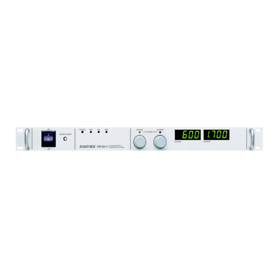
Features and Specifications Front Panel Controls Figure 1.1 Power Supply Front Panel Release 2.2... -
Page 16: Rear Panel Connectors And Switch
Features and Specifications Rear Panel Connectors and Switch Rear Panel Connectors and Switch The input AC power, output DC power, as well as the remote program sense and monitor connector are located on the rear panel. The program and monitor function selector switch (SW1) is located internally on the main PCB. - Page 17 Features and Specifications Controls, Connectors, and Indicators Figure 1.2 Power Supply Rear Panel Release 2.2...
- Page 18 Features and Specifications Controls, Connectors, and Indicators Figure 1.3 J3 Program, Sense, and Monitor Connector Description Operating Manual for XKW 1kW Series Power Supply...
-
Page 19: Specifications
Features and Specifications Specifications Specifications These specifications are warranted over a temperature range of 0 °C to 50 °C. Electrical Specifications Specifications are subject to change without notice. Table 1.2 Electrical Specifications for 8 V to 60 V Models Models 8-125 20-50 33-33... - Page 20 Features and Specifications Specifications Table 1.3 Electrical Specifications for 80 V to 600 V Models Models 80-13 150-7 300-3.5 600-1.7 Output Ratings: Output Voltage 0-80 V 0-150 V 0-300 V 0-600 V Output Current 0-125 A 0-7 A 0-3.5 A 0-1.7 A Output Power 1040 W...
-
Page 21: Additional Specifications
Features and Specifications Specifications Additional Specifications Rise Time (No Load, Full Load): 300 ms (full load and no load) Fall Time (No Load): 200 ms Fall Time (Full Load): Voltage Mode Transient Response: 1 ms Time Delay from power on until 2 s maximum output stable Measured with stepped 0-10 V analog programming source and a resistive load. -
Page 22: Remote Programming And Monitoring
Features and Specifications Specifications Remote Programming Monitoring Remote Start/Stop and Interlock TTL compatible input. Contact Closure, 12-250 Vac or 12-130 Vdc Remote Monitoring 0-5 V Remote Programming and Programming better than 5% Monitoring Accuracy Monitoring voltage 10% Current 5% Maximum Remote Sense Line Drop Compensation 1. -
Page 23: Mechanical Specifications
Features and Specifications Specifications Mechanical Specifications Front Panel V and I Control 10-turn voltage and current potentiometers Front Panel Voltage Control 0.02% of V max Resolution Front Panel Voltage and Current 3 or 4 digit LED readouts for each. Meters Table 1.2 Table 1.3 for accuracy. - Page 24 Features and Specifications Specifications Operating Manual for XKW 1kW Series Power Supply...
-
Page 25: Introduction
Section 2. Installation Introduction This section provides recommendations and procedures for inspecting, installing, and testing the power supply. Basic Setup Procedure Table 2.1 for a summary of the basic setup procedure and an overall view of the subsections in Section 2. -
Page 26: Inspection, Cleaning, And Packaging
Installation Inspection, Cleaning, and Packaging Inspection, Cleaning, and Packaging Initial When you first receive your unit: Inspection 1. Inspect the unit for scratches and cracks, and for broken switches, connectors, and displays. 2. Ensure that the packing box contains the AC power cord. 3. -
Page 27: Returning Power Supplies To The Manufacturer
Returning Power Supplies to the Manufacturer Returning Power Supplies to the Manufacturer Return Before returning a product directly to Xantrex you must obtain a Return Material Authorization (RMA) number and the correct factory “Ship To” address. Products Material must also be shipped prepaid. Product shipments will be refused and returned at your... -
Page 28: Packaging For Shipping Or Storage
Installation Returning Power Supplies to the Manufacturer Packaging for Follow these instructions to prepare the unit for shipping or storage. Shipping or 1. When returning the unit or sending it to the service center, attach a tag to the unit Storage stating its model number, available from the front panel label, and its serial number, available from the rear panel label. -
Page 29: Location, Mounting And Ventilation
Installation Location, Mounting and Ventilation Location, Mounting and Ventilation Ventilation The power supply may be used in rack mounted or benchtop applications. In either case, sufficient space must be allowed for cooling air to reach the ventilation inputs Requirements on the right hand side of the unit and for the fan exhaust air to exit from the rear of the unit. -
Page 30: Ac Input Power
Installation AC Input Power AC Input Power AC Input Voltage Selection WARNING Exercise caution when using and servicing power supplies. High energy levels can be stored at the output terminals on all power supplies in normal operation. In addition, potentially lethal voltages exist in the power circuit and the output connector of power supplies which are rated at 40V and over. -
Page 31: Input Line Impedance
Installation AC Input Power 100-130Vac 20A Input To convert the unit for use with a 100-130Vac 20 A input, perform the following steps: 1. Ensure that the unit is switched off and disconnected from any power source. 2. Remove the Phillips head screws which secure the cover and then remove the cover from the unit. -
Page 32: Functional Tests
Installation Functional Tests Functional Tests Before connecting the unit to an AC outlet, make sure that the power switch is in the OFF position and that the voltage and current controls are turned fully counter clockwise. Check that the J3 mating connector on the rear of the unit is in place with jumpers connected for local operation as shown below. -
Page 33: Current Mode Operation
Installation Functional Tests Current Mode To check current mode operation, proceed as follows: Operation 1. Rotate the VOLTAGE and CURRENT controls fully counterclockwise. 2. Rotate the VOLTAGE control 1/2 turn clockwise. 3. Connect a high current DC ammeter across the rear output terminals, observing correct polarity. -
Page 34: Load Connection
Installation Load Connection Load Connection Reliable performance of the power supply can be obtained if certain basic precautions are taken when connecting it for use on the lab bench or installing it in a system. To obtain a stable, low noise output, careful attention should be paid to factors such as conductor ratings, system grounding techniques and the way in which the load and remote sensing connections are made. -
Page 35: Output Cord Strain Relief
Installation Load Connection Proper connection of distributed loads is an important aspect of power supply application. A common mistake is to connect leads from the power supply to one load, from that load to the next load, and so on for each load in the system. In this parallel power distribution method, the voltage at each load depends on the current drawn by the other loads and DC ground loops are developed. - Page 36 Installation Load Connection Assembly Instructions 1. Snap off the rectangular bushing attached to each piece of the strain relief. See Figure 2.3. Figure 2.3 Strain Relief (One piece, inside view) 2. Install bushings on strain relief pieces, as required. Cable diameter must be between 0.120"...
-
Page 37: Local And Remote Sensing
Installation Local and Remote Sensing Local and Remote Sensing The use of remote sensing permits the regulation point of the power supply to be shifted from the output terminals (local sensing) to the load or other distribution terminals, thereby automatically compensating for the voltage losses in the leads supplying the load (provided these losses do not exceed 0.5V/line for the 8V model or 1V/line for all other models). - Page 38 Installation Local and Remote Sensing Operating Manual for XKW 1kW Series Power Supply...
-
Page 39: Single Supply Operation (Local Mode)
Section 3. Operation Single Supply Operation (Local Mode) To operate the power supply in local mode, first install the unit and connect the load following the instructions in Section 2, “Installation”. For further information see “Remote Programming of Output Voltage and Current Limit” on page 47 complete description of switch SW1 functions. -
Page 40: Multiple Supplies
Operation Multiple Supplies Multiple Supplies CAUTION All remote programming input and monitoring lines are internally referenced to the supply’s negative output. Do not reference remote programming or monitor lines to the supply’s positive output. J3 pin 6 (ground) is directly connected to the supply’s negative output. -
Page 41: Parallel Operation
Operation Multiple Supplies Parallel Parallel operation is used to obtain a higher current single output supply using two or more single units. Set all of the outputs to the same voltage before connecting the Operation positive terminals (+) and negative terminals (-) in parallel. The total current available is the sum of the maximum currents of each supply. -
Page 42: Over Voltage Protection (Ovp)
Operation Over Voltage Protection (OVP) Over Voltage Protection (OVP) The OVP circuit allows for protection of the load in the event of a remote programming error, incorrect voltage control adjustment, or power supply failure. The protection circuit monitors the output and reduces the output voltage and current to zero whenever a preset voltage limit is exceeded. -
Page 43: Remote Programming Of Ovp With External Voltage Sources
Operation Over Voltage Protection (OVP) Remote To remotely program the OVP trip level using a 0-5V DC (Figure 3.2) or 0-10V DC (Figure 3.3) voltage source use the following procedure. Programming of OVP With 1. With the unit off and disconnected from its AC source, remove the cover and set External switch SW1-4 closed (default factory setting) for 0-5V programming or open for Voltage... - Page 44 Operation Over Voltage Protection (OVP) Figure 3.3 SW1/J3 Configuration for 0-10Vdc OVP Programming (J3 sense line, voltage and current control jumpers shown set for local operation) Operating Manual for XKW 1kW Series Power Supply...
-
Page 45: Remote Programming Of Ovp With An External Resistance
Operation Over Voltage Protection (OVP) Remote To remotely program the OVP trip level using a 5k ohm external potentiometer, use the following procedure. Programming of OVP with 1. With the unit off and disconnected from its AC source remove, the cover, set an External switch SW1-8 open and check that switch SW1-4 is closed (default factory Resistance... -
Page 46: Remote Programming Of Ovp With External Current Sources
Operation Over Voltage Protection (OVP) Remote To remotely program the OVP trip level using a 0-1mA current source, use the following procedure. Programming of OVP with 1. With the unit off and disconnected from its AC source, remove the cover and set External switches SW1-4 and SW1-8 closed (default factory setting). -
Page 47: Remote Ovp Sensing
Operation Over Voltage Protection (OVP) Remote OVP The default configuration for the OVP circuit senses the output voltage at the power supply output terminals. For applications using remote sensing where there is a need Sensing to accurately monitor the actual load voltage, the following procedure allows the OVP sense point to be shifted from the power supply output to the sense line connection points. -
Page 48: Remote On/Off
Operation Remote ON/OFF Remote ON/OFF CAUTION The external voltage applied to pins 1 and 2 (Shutdown input and return) cannot exceed 250V rms with respect to the supply’s negative output or the supply may be damaged. This feature is useful in test applications requiring remote ON-OFF control of the output. -
Page 49: Remote Programming Of Output Voltage And Current Limit
Operation Remote Programming of Output Voltage and Current Limit Remote Programming of Output Voltage and Current Limit Remote Programming Switch SW1 CAUTION The remote programming input is internally referenced to the supply's negative output. Do not connect remote programming input lines (J3 pins 9 and 10) to the supply's positive output. -
Page 50: Programming With External Voltage Sources
Operation Remote Programming of Output Voltage and Current Limit Programming The output voltage can be programmed using either a 0-5Vdc or 0-10Vdc external voltage source. To program the output voltage with a 0-5Vdc source, set switch With External SW1-3 open (default factory setting) and remove the jumpers connecting pins 8 to 9 Voltage and 20 to 21 on connector J3. - Page 51 Operation Remote Programming of Output Voltage and Current Limit The output current limit can be programmed using a 0-100mVdc, 0-5Vdc or 0-10Vdc external voltage source. Selection of the programming voltage is done using switches SW1-1 and SW1-2 as indicated in Table 3.1.
-
Page 52: Programming With An External Resistance
Operation Remote Programming of Output Voltage and Current Limit Programming The output voltage and current limit can be programmed using a 5k ohm external potentiometer. With an External To program the output voltage, set switch SW1-3 open (default factory setting) and Resistance remove the jumpers connecting pins 8 to 9 and 20 to 21 on connector J3. -
Page 53: Programming With An External Current Source
Operation Remote Programming of Output Voltage and Current Limit Programming The output voltage and current limit can be programmed using an external 0-1mA current source. With an External To program the output voltage, set the front panel voltage control to maximum, set Current switch SW1-3 open (default factory setting) and remove the jumper between pins 20 Source... -
Page 54: Remote Monitoring And Status Indicators
Operation Remote Monitoring and Status Indicators Remote Monitoring and Status Indicators Readback signals for remote monitoring of the output voltage and current are available at connector J3 on the rear of the unit. A 0-5V (uncalibrated) signal between pins 19 (positive) and 12 (negative) represents 0-100% of the rated output voltage. -
Page 55: Using Over Temperature Protection (Otp)
Operation Using Over Temperature Protection (OTP) Using Over Temperature Protection (OTP) The OTP circuit protects the power supply in the event of excessive temperature. The protection circuit monitors the temperature of a supply heatsink using a temperature sensor, and will activate the internal shutdown circuit whenever the maximum temperature is exceeded. - Page 56 Operation Using Over Temperature Protection (OTP) Operating Manual for XKW 1kW Series Power Supply...
-
Page 57: Introduction
Section 4. Calibration Introduction WARNING Exercise caution when using and calibrating a power supply. High energy levels can be stored at the output voltage terminals on a power supply in normal operation. In addition, potentially lethal voltages exist in the power circuit and on the output and sense connectors of a power supply with a rated output greater than 40 V. -
Page 58: Calibrating
Calibration Calibration Setup Calibrating Figure 4.1 Calibration Adjustment Locations Table 4.1 Calibration Trimpot Designations and Parameters Designation Assembly Parameter Affected Output Current Monitor Calibration Output Current Monitor Offset Current Control Circuit Offset Output Current Range Voltage Control Circuit Offset Output Voltage Range Front Panel Voltmeter Calibration Front Panel Ammeter Calibration Operating Manual for XKW 1kW Series Power Supply... - Page 60 Xantrex Technology Inc. 8999 Nelson Way Burnaby, British Columbia Canada V5A 4B5 604 422 8595 Tel 604 421 3056 Fax 800 667 8422 Toll Free North America prg.info@xantrex.com www.xantrex.com TM-10OP-01XN PRINTED IN CANADA...
Need help?
Do you have a question about the XKW 8-125 and is the answer not in the manual?
Questions and answers