TESTO 6381 Instruction Manual
Differential pressure transmitter, probes
Hide thumbs
Also See for 6381:
- Instruction manual (92 pages) ,
- Instruction manual (86 pages) ,
- Instruction manual (84 pages)

Related Manuals for TESTO 6381


Summary of Contents for TESTO 6381
- Page 1 6381 Ethernet · differential pressure transmitter testo 6610 · Probes P2A software · Parameterizing, adjusting and analyzing software Instruction manual Volume 1...
-
Page 3: Safety And The Environment
Use only original spare parts from Testo. Any additional work must only be carried out by authorized personnel. Otherwise testo will not accept any responsibility for the proper functioning of the instrument after repair and for the validity of certifications. -
Page 4: About This Document
2 About this document About this document > Please read this documentation through carefully and familiarize yourself with the product before putting it to use. Pay particular attention to the safety instructions and warning advice in order to prevent injuries and damage to the products. >... -
Page 5: Table Of Contents
Inserting Ethernet module (order no. 0554 6656) ............. 21 4.3.2. Assembling the instrument ..................23 4.3.2.1. Wall mounting (for testo 6611, 6613, 6614, 6615, 6617 probes) ....23 4.3.2.2. Duct mounting (for testo 6612 probes) ............24 4.3.3. Connecting the instrument ..................25 4.3.3.1. - Page 6 4.3.4.10. Analog output adjustment ................. 56 4.3.4.11. n-point adjustment (pressure) ..............57 4.3.4.12. High-humidity adjustment for testo 6614 ..........59 4.3.4.13. Self adjustment of testo 6615 trace humidity probe ........60 4.4. Operation ................62 4.4.1. Relationship between user menu and mini-DIN socket is active ........ 62 4.4.2.
-
Page 7: Transmitter
Ethernet. Furthermore, it is possible to issue an alarm for those responsible for the process, if necessary. 4.1.2. Scope of delivery The scope of delivery of the testo 6381 transmitter includes the following: • Key cover •... -
Page 8: Accessories
4 Transmitter 4.1.3. Accessories The following accessories are available for the testo 6381 transmitter, amongst others: • Protection caps for probes • Mains unit • P2A software (parameterizing, adjusting and analyzing software) • Assembly accessories Information about accessories and their order numbers can be found in volume 2, 8.2 Accessories and spare parts or... - Page 9 Upon delivery and following a factory reset the readings are shown in the display in the unit that was ordered via the KMAT option Fxx, see volume 2, 8.2.1. Ordering options for 6381 transmitter (0555 6381). Humidity and temperature measuring range •...
- Page 10 4 Transmitter Meas. cycle • 1/sec Interface • Mini-DIN for P2A software (parameterizing and adjusting software) and handheld testo 400/650 Voltage supply • 4-wire (separate signal and supply lines): 20 to 30 V AC/DC, 300 mA power consumption Maximum load •...
- Page 11 4 Transmitter Relay • 4 relays, 250 V AC/DC, 3 A (optional) Display • 2-line LCD with plain text line (optional) Operating temperature • -5 to 50 °C/23 to 122 °F Storage temperature • -20 to 60 °C/-4 to +140 °F Process temperature •...
-
Page 12: Dimensions
4 Transmitter 4.1.5. Dimensions Dimensions in mm with M20 cable couplings With NPT cable coupling With M plug-in connection... -
Page 13: Product Description
R3 and R4 relays 11 Eyelet for measuring point panel 12 M 20 x 1.5 screw connection*, e.g. R1 and R2 relays 13 Probe connector (testo 6610) 14 Upper part of housing * Alternatively, NPT cable couplings or M plug-in connections are available A... -
Page 14: Usable Probes
(M3 x 6 screw) 8 Plastic bracket for assembly on rear panel 4.2.2. Usable probes The testo 6381 transmitter can be used with the following probes: Probes Article no. Characteristic testo 6611 0555 6610-L11 Wall probe version; accuracy to ±1 % RH;... -
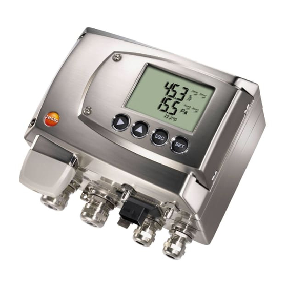
Page 15: Display And Keypad
-40 to +356 °F, sensor soldered 4.2.3. Display and keypad The display option allows operation of the testo 6381 transmitter via the display and four keys. The LCD display consists of two 7-segment lines for displaying readings and units and of an information line (for status messages, for example). -
Page 16: Parameters
4 Transmitter • 1 or optionally 3 voltage outputs of 0 to 1 V/0 to 5 V/0 to 10 V (4-wire). The transmitter can be ordered with three analog outputs as an option. The optional three channels are galvanically isolated. 4.2.7. -
Page 17: Scaling
4 Transmitter 4.2.8. Scaling There are three types of min./max. values: 1 The measuring range: The maximum sensor performance is in this range. Values outside of the measuring range are displayed via messages, for example. Measuring range, see table (below). 2... - Page 18 4 Transmitter Measuring range/ Maximum scaling standard scaling -10 to 10 Pa -20 to 20 Pa -50 to 50 Pa -100 to 100 Pa -100 to 100 Pa -200 to 200 Pa -500 to 500 Pa -1000 to 1000 Pa -10 to 10 hPa -20 to 20 hPa -50 to 50 hPa...
- Page 19 Psychrometer °C temperature °F Water content 99999 99999 (vol) For constant use in high humidity (> 80% rF at ≤ 30°C for > 12 h, > 60% rF at > 30°C for > 12 h), please contact us via www.testo.com/service-contact...
-
Page 20: Alarm Handling
The testo 6381 monitors limit values with the help of relays. If a reading is outside the limit values, a relay to be specified by the user is switched. -
Page 21: Commissioning
Inserting Ethernet module (order no. 0554 6656) The Ethernet module can be ordered retroactively as an accessory. It can easily be installed in the testo 6381 transmitter. ✓ The probe connector must be disconnected. 1. Loosen screw connection (1) of service flap and open the flap. - Page 22 4 Transmitter 4. Place Ethernet module (A) on lower part of instrument (4). First set the desired operating mode via the DIP switch (see 4.3.3.6. Setting the Ethernet module) before fixing the instrument in place. 5. Set on upper part of instrument (5) and fix in place using the housing screws (6) provided in the accessories.
-
Page 23: Assembling The Instrument
4.3.2. Assembling the instrument 4.3.2.1. Wall mounting (for testo 6611, 6613, 6614, 6615, 6617 probes) Attaching rear panel bracket 1. Remove locking screw (see item (4) of drawing below) and detach rear panel bracket from plastic bracket (see item (2) of drawing below). -
Page 24: Duct Mounting (For Testo 6612 Probes)
3. Insert probe connector (5) into socket until it engages. 4.3.2.2. Duct mounting (for testo 6612 probes) 1. Hold wall/duct bracket (order no. 0554 6651) (6) against duct wall (8) and mark drill holes for wall/duct bracket and probe shaft. -
Page 25: Connecting The Instrument
4 Transmitter 5. Fix the correct position of the probe shaft (9) with screw (11) and mark (insert probe shaft as far as possible). 6. Slide plastic bracket (2) on the back of the transmitter onto bracket (3, 4) until it engages. Take the weight of the transmitter into account. - Page 26 4 Transmitter 2. Loosen and remove housing screws (2). The Ethernet module (A) is already detached from the upper and lower parts of the housing by removing the housing screws (2). 3. Remove upper part of housing (3) and place on a clean surface. 4....
- Page 27 4 Transmitter WARNING Electrical voltage Danger of injury! > De-energize the mains connection before connecting the transmitter. Only have the transmitter wired and connected by authorized personnel with the voltage disconnected.
-
Page 28: Overview Of Terminals
4 Transmitter 4.3.3.1. Overview of terminals 1 Lower part of housing 7 Earthing terminal (internal) 2 Relay board (option) 8 M 16 x 1.5 screw connection* 3 Relay terminals 9 Earthing terminal (external) 4 Insulating trough for relay 10 M 20 x 1.5 screw connection* board 11... -
Page 29: Connecting Voltage Supply And Analog Outputs
4 Transmitter 4.3.3.2. Connecting voltage supply and analog outputs Terminal strip for voltage supply and analog outputs, item (5) of 4.3.3.1. overview of terminals 1. Feed cable with voltage supply and analog signal lines through opened M 16 x 1.5 screw connection (item (8) in the 4.3.3.1. overview of terminals). -
Page 30: Connecting The Relay Outputs
4 Transmitter 1. Feed connection cables of the one, or optionally three, channels through opened M 16 x 1.5 screw connection (item (8) in the 4.3.3.1. overview of terminals). 2. Strip the cable ends, clamp wire end ferrules on and screw to channel terminals as shown in diagram. - Page 31 4 Transmitter Connection note • For the connection, a double-insulated mains cable (sheathed cable) with a cross-section of at least 1.5 mm² must be used. • Cable connection (2) may not be routed in a loop within the tray (1). •...
- Page 32 4 Transmitter Use of relay as NC contact (NC = normally closed) 1 Alarm/status light (example of installation) 2 250 V AC/DC, 3 A The busy light (alarm/status light) is permanently on until the relay opens or the circuit is interrupted. This circuit can therefore be used to monitor the functionality of the alarm circuit, as a cable break, for instance, is indicated by the busy light going off.
-
Page 33: Plug-In Connection Option
4 Transmitter The busy light (alarm/status light) only comes on when the relay is switched (closed). Monitoring the functionality of the alarm circuit is therefore not possible with this switching operation. 5. C lose M 20 x 1.5 screw connection (item (10) in 4.3.3.1. overview of terminals). -
Page 34: Creating The Pe/Earthing Terminal
- Ch3 4.3.3.5. Creating the PE/earthing terminal As the testo 6381 has a metal housing, we recommend that the instrument be earthed. This can be done using the earthing terminal within the instrument (1) or the earthing terminal outside of the instrument (2). -
Page 35: Setting The Ethernet Module
• Saveris subscriber function (DIP switch no. 1 = on, DIP switch no. 2 = on), testo 6381 is used as a testo Saveris component. • XML server function (DIP switch no. 1 = off, DIP switch no. 2 = on), integration of the testo 6381 into the customer's Ethernet system. - Page 36 4 Transmitter 2. Set DIP switch no. 1 (1) at Ethernet module. In the picture: DIP switch no. 1 off, DIP switch no. 2 on 3. Set Ethernet module on lower part of housing (see arrow). 4. For the configuration of the Ethernet module, see following chapter.
-
Page 37: Closing The Instrument
4 Transmitter 4.3.3.7. Closing the instrument 1. Place Ethernet module (A) on lower part of instrument (1). 2 Set on upper part of instrument (2) and fix in place using housing screws (3). -
Page 38: Ethernet Communication
In general, the Ethernet module performs two functions: • a corresponding testo 6381 becomes a Saveris subscriber • a corresponding testo 6381 can be integrated into any Ethernet systems 4.3.4.2. Mains connection > Connect the network cable to the transmitter. -
Page 39: Led Status Displays
Saveris (testo Saveris Ethernet Wizard). 1. Set the IP address with the P2A software (see volume 2, 7.3. Using the software) or with the testo Saveris Ethernet Wizard (see instruction manual). 2. Disconnect service plug. 3. Disconnect the Ethernet module from the voltage supply. -
Page 40: Integration Into Customer's Ethernet System
Saveris Professional Client is installed • Select Saveris Viewer (limited functionality). The entry is available if Saveris Viewer is installed Testo Saveris software program window is opened with Select project dialogue. If the software will not start, check whether the testo... - Page 41 XML file is the next page) located H:/wget/wget-complete-stable /wget --post-file= C:/usersettings.xml 254.169.100.100/config/ setusersettings The Ethernet module supports reading out of • Readings • Instrument type (testo 6381) • Firmware date and version (testo 6381) • Status and status messages (testo 6381)
- Page 42 4 Transmitter • Alarm messages (testo 6381) • Service hour counter (testo 6381 and probe) as well as the reading and writing of the: • Adjustment data (testo 6381) • Configuration data of analog outputs (testo 6381) • Configuration data of relays (testo 6381) •...
- Page 43 4 Transmitter Description Parameter Answer (see Appendix) param=0 (relay 1) /config/getreldefinition Read off relay information reldefinition.xml param=1 (relay 2) of transmitter param=2 (relay 3) param=3 (relay 4) /config/getheatertime Read off sensor heating heatertime.xml information /config/getoptions Read off options of options.xml transmitter /config/getcollectivealarm Read off alarm messages collectivealarm.xml...
- Page 44 4 Transmitter Description of the XML elements General elements XML tag Description Type measurement_value Parent element. Contains the child elements value, unit, resolution value Reading Numerical, decimal number unit Unit ASCII number_values Qty. Numerical, whole number Elements in calibration.xml XML tag Description Type calibration_data...
- Page 45 4 Transmitter XML tag Description Type month Month Numerical, whole number Numerical, whole number Elements in heatertime.xml XML tag Description Type heatertime Base element. Contains the child element heatertimeoff heatertimeoff Time sensor heating off in min Numerical, whole number Elements in hourscount.xml XML tag Description Type...
- Page 46 4 Transmitter Elements in options.xml XML tag Description Type options Base element. Contains the child elements device_options, production_options device_options See device_options description Numerical, whole number production_options See production_options description Numerical, whole number Elements in reldefinition.xml XML tag Description Type relay_data Base element.
- Page 47 4 Transmitter XML tag Description Type statecounter Counter Numerical, whole number Elements in usersettings.xml XML tag Description Type usersettings Base element. Contains the child elements (pressure)* (abs_pressure_pa_process)*, (humidity_process)*, (temperature_c_process)*, (humidity_norm)*, (abs_pressure_pa)*, h2o2, setting_display, backlight, contrast, language, disp_msg, h2o2_prozess pressure Absolute pressure Numerical, decimal number h2o2 H2O2 value...
- Page 48 4 Transmitter XML tag Description Type Pressure process data, process humidity_process Numerical, decimal number humidity in % RH Pressure process data, process temperature_c_process Numerical, decimal number temperature in °C Humidity process data, absolute abs_pressure_pa Numerical, decimal number pressure in Pa Elements in versions.xml XML tag Description...
- Page 49 4 Transmitter xxxx xxxx xxxx xxxx xxxx xxx1 2222 3334 2 free 3 0=4 to 20 mA 1=0 to 20 mA 2=0 to 1 V 3=0 to 5 V 4=0 to 10 V 4 0=1 analog output 1=3 analog outputs device_options description Content of device_options is a double word type number (32 bit).
-
Page 50: Adjusting The Instrument
More information can be found in the download area at www.testo.com. 4.3.4.6. Adjusting the instrument The testo adjusting concept allows the entire signal chain from the sensor signal (probe) and the digital signal (within the transmitter) through to the analog signal (transmitter output signal) to be adjusted (see diagram). -
Page 51: Overview: Adjustment Keys And Test Contacts
Either the 1-point adjustment or 2-point adjustment is suitable for adjusting the sensor signal - digital signal chain. The testo 6381transmitter has digital probes whose adjustment information is stored in the probes' internal memory. Both 1-point and 2-point adjustments can thus be carried out on another testo 6381 (e.g. -
Page 52: 1-Point Adjustment (Offset - Humidity/Temperature)
Please note that the 1-point adjustment is generally performed on the basis of the % RH and °C/°F parameters. Adjusting testo 6381 using testo handheld instrument ✓ The service flap is open, a testo 400/650 handheld instrument with a precision humidity probe is ready. - Page 53 1. Connect testo handheld instrument 400/650 (1) with connected humidity reference probe (3) (order no. reference set 0699 3656/20) to the service interface (5) of the testo 6381 via the adjustment adapter (2) (connected to probe socket 1 of the handheld instrument).
-
Page 54: 2-Point Adjustment (Humidity/Temperature)
6615 (trace humidity) probes. The reference conditions should be generated in a humidity generator to adjust these probes. In addition, these probes can also be adjusted at a third adjustment point by Testo Service. • testo 6614: third adjustment point at 90 % RH •... - Page 55 (humidity generator) ✓ The service flap of the testo 6381 is open: 1. Expose the humidity probe of the testo 6381 to the reference condition of 11.3 % RH for at least 1.5 hours at 25 °C. 2. After this equalization period, press the 11.3 %...
-
Page 56: Analog Output Adjustment
8. Contact ch. 2- Adjusting analog outputs 1 and 2 (optional) ✓ With testo 6381 with current output: Load of max. 500 is connected to channel that is to be adjusted (see 4.3.3.4. Plug-in connections for power supply and channels) ✓... -
Page 57: N-Point Adjustment (Pressure)
4.4.6.9. Performing the 2-Points-Adjustment for 20% RH and 80 % RH). 3. Disconnect connections between the multimeter and the contacts of the testo 6381 and close the service flap. Adjusting analog output 3 (optional) If the optional third analog output is to be adjusted, a cable connection to measure the analog value must be installed. - Page 58 ✓ A precise pressure sensor (5-times more accurate than the transmitter, e.g. DPC precision pressure sensor from testo industrial services) is available. 1. Connect the positive output of the pressure sensor (3) to the...
-
Page 59: High-Humidity Adjustment For Testo 6614
4 Transmitter 4.3.4.12. High-humidity adjustment for testo 6614 With the testo 6614, the rear of the Testo humidity sensor is heated, creating a microclimate around the sensor (within the filter) that is constantly 5 K warmer than the actual process conditions. -
Page 60: Self Adjustment Of Testo 6615 Trace Humidity Probe
-60 °C To this end, a temperature sensor is fitted on the back of the testo 6615 which is used as a heater. A humidity and temperature value pair is taken in both the unheated and heated state. The deviation of the probe obtained from these pairs of values is automatically corrected. - Page 61 P2A software. • In the factory setting, a third adjustment point (-40 °C ) is approached for the testo 6615 in addition to the 2-point adjustment. This special adjustment can be performed again by your Testo Service team if necessary.
-
Page 62: Operation
4.4.1. Relationship between user menu and mini-DIN socket is active The testo 6381 can be parameterized using either the user menu or the P2A software (see volume 2, 7. Parameterizing, adjusting and analyzing software (P2A software)). The testo 6381 transmitter can only be operated via the display and keypad if the display option is available. -
Page 63: Password Protection
4 Transmitter Attaching the key cover ✓ The service flap is opened, see 4.3.3. Opening the instrument,. 1. Unscrew screws (3) and remove key frame (2). 2. Insert key cover (1) into service flap and tighten screws (3). 3. Close and screw down the service flap. 4.4.3. - Page 64 4 Transmitter • Main Menu Analysis • Main Menu Messages • Main Menu Ident • Main Menu Adjust • Main Menu Reset 1 Channel 1 display 2 Channel 2 display 3 Channel 3 display or for messages Four keys enable the user to navigate/scroll through the menus and enter/amend values and settings: Function/description •...
-
Page 65: Overview Of The Testo 6381 User Menu
4 Transmitter 4.4.5. Overview of the testo 6381 user menu... - Page 66 4 Transmitter...
- Page 67 4 Transmitter...
-
Page 68: The Individual Main Menus
The individual main menus 4.4.6.1. Editing main menu of channel 1 An overview is given in Overview of the testo 6381 user menu). You can perform basic settings for channel 1. 1. In the Measuring Mode press SET, select Main Menu Channel 1 with ... -
Page 69: Editing Main Menu Alarm
4 Transmitter 4.4.6.4. Editing Main Menu Alarm With the alarm, the relays, available as options, are programmed. In addition, the alarm statuses are shown on the display (top right) (even without relays). You can choose whether the alarm is to be used to monitor limit values or as a collective alarm. -
Page 70: Editing Main Menu Settings
If an alarm is assigned to the collective alarm, the relay is switched and a visual alarm can be issued via the display as soon as (at least) one of the warning or error messages of the testo 6381 transmitter (or the connected testo 6610 probe) becomes active. - Page 71 4 Transmitter You can edit settings for: • Display • Language • Code • Units ◦ Absolute pressure ◦ Area ◦ Temperature • Standard data ◦ Absolute pressure ◦ Temperature • Pressure process data ◦ Absolute pressure ◦ Humidity ◦ Temperature ◦...
- Page 72 4 Transmitter • Backlight 24h on using or and confirm with SET. Select Off: The display light switches off automatically if no button was pressed for 10 seconds. On: The display light is activated 3. Return to Display Settings with and use...
- Page 73 4 Transmitter with or , confirm selection with 1. Select Standard data or cancel with ESC. 2. Select the required variable (absolute pressure/temperature) with or , confirm selection with or cancel with ESC. 3. Scroll one digit to the right using and increase value of digit by 1 using .
-
Page 74: Editing Main Menu Analysis
4. Accept setting by pressing and test with multimeter (minimum requirement: resolution 6.5 digits, at least 2-times more accurate than the 6381) as follows: Analog output 1 or 2: Via test contacts under service flap, see diagram. 1 Channel 1 test contacts 2... -
Page 75: Editing Message Main Menu
4 Transmitter and use or to 6. Return to Test Analog Output with continue to Test Relay Output. Testing functionality of the pressure sensor (Test pressure sensor) This function is only required to calibrate the pressure sensor. Testing functionality of relay outputs with ... - Page 76 4 Transmitter 1 Operating hours at the time of message 2 Message code (see 4.5. Status, warning and error messages). 3 Message text 4 Message number (example: "4/7" refers to the fourth of seven messages) 5 Number of messages present (example: "4/7" refers to the fourth of seven messages) Using the P2A software (see volume 2, 7.
-
Page 77: Calling Up Main Menu Ident
4 Transmitter 4.4.6.8. Calling up Main Menu Ident 1 Instrument or probe type 2 Build number 3 Firmware version 4 Serial number The serial numbers of the transmitter and probe can be read off. 1. In the Measuring Mode press SET, select Main Menu Ident with ... - Page 78 4 Transmitter The 2-point adjustment for the adjustment points 20 %RH and 80 %RH is carried out via the user menu. For the adjustment points 11.3 %RH and 75.3 %RH, the 2- point adjustment is carried out via the adjustment buttons or the P2A software, see 4.3.4.9.
- Page 79 4 Transmitter Performing analog adjustment Please refer to 4.3.4.10. Analog output adjustment. 1. In the Measuring Mode press SET, select main menu Adjust with or and confirm selection with SET. Each channel is adjusted at three points in the analog range (at 10 %;...
-
Page 80: Editing Reset Main Menu
• Warning messages • Error messages The status and warning messages for the respective testo 6610 probes connected to the transmitter can be evaluated via the P2A software. All messages are stored in the transmitter with an operating hours stamp. Use the user menu (see 4.4.6.7. Editing Message main menu) or the P2A software (see volume 2, 7.3.5. -
Page 81: Status Messages
4 Transmitter 4.5.1. Status messages Status messages show the current operating status of the testo 6381. Message Display Description 02506 Sensor Message appears while the initialization transmitter is starting up. If the message disappears, the transmitter is ready for operation. -
Page 82: Warning Messages
As part of the 2-point adjustment, 80 % an adjustment is performed at 80 % RH 02105 Self-adjustment For testo 6615 probe only: The active probe performs an automatic self- adjustment 4.5.2. Warning messages Warning messages show an early warning or a current malfunction which may negatively impact measuring. - Page 83 Take measures to reached, condensation reduce process developing humidity 02807 Values less than The adjustment or Check adjustment (via 0 % RH** sensor is faulty P2A adjustment history, perform 2-point adjustment where necessary). If the problem persists, contact Testo Service...
-
Page 84: Transmitter Error Messages
4 Transmitter Message Display Cause Remedying of fault 02809 Sensor early For testo 6617 probe Carry out visual warning* only: The cover inspection. If the mirror- electrode of the sensor like surface of the is damaged; this may sensor is dirty or... -
Page 85: Handling Alarm Messages
4 Transmitter Message Display Cause Remedying of fault 03105 Self-adjustment For testo 6615 probe Contact Testo Service error only: The automatic self-adjustment was faulty 03106 Adjustment error The adjustment of the Contact Testo Service probe was faulty 01115 Low adjustment... - Page 86 4 Transmitter Shown on the Can be used for Additional display collective alarm message end Alarm 4 Transmitter reset Reset Min/Max Transmitter refresh User Setting Change Analog adjustment 1-point adjustment 2-point adjustment 11.3% 2-point adjustment 75.3 % Probe reset 2-point adjustment drift T ambient high T ambient low...
-
Page 87: Namur Fault Conditions
4 Transmitter Perform the Confirm message function (acknowledgement of the alarm via the control keys on the transmitter): • The message/alarm is no longer shown on the display and the optical alarm goes out, where applicable. If multiple messages/alarms are active at the same time, all are reset simultaneously. -
Page 88: Maintenance And Cleaning
4 Transmitter Status Display Class Analog output message in value in the display display Watchdog Previous Error 21 mA 3.8 mA 1.1 V 5.5 V 11 V error value stops Value below Reading Underrange 0 mA 3.8 mA min. scale Value above Reading Overrange 20.5 mA 20.5 mA 1.1 V 5.5 V 11 V... - Page 89 4 Transmitter...
- Page 90 4 Transmitter...
- Page 91 4 Transmitter...
- Page 92 0970 6381 de 04 Vol.1...
- Page 93 6381 Ethernet · differential pressure transmitter testo 6610 · Probes P2A software · Parameterizing, adjusting and analyzing software Instruction manual Volume 2...
-
Page 95: Contents
6.4.1. Replacing filters/protection caps ................130 6.4.1.1. Replacing the filter/protection caps for testo 6611 wall version ....130 6.4.1.2. Replacing the filter/protection cap for testo 6612 duct version ....131 6.4.1.3. Replacing the filter/protection cap for duct versions ....... 132 6.4.2. - Page 96 7.3.4.4. Adjusting the analog output ..............161 7.3.5. Transmitter history ....................163 Tips and assistance ............... 168 8.1. Questions and answers ............. 168 8.2. Accessories and spare parts ..........168 8.2.1. Ordering options for 6381 transmitter (0555 6381) ..........171...
- Page 97 5 Contents 8.2.2. Ordering options for testo 6610 probes (0555 6610) ..........175...
-
Page 98: Testo 6610 Probes
6610 probes 6.1. Specifications 6.1.1. Functions and use The plug-in, adjusted probes from the testo 6610 family are used together with the testo 6381 transmitter. These measuring units are suitable for the following applications, for example: • Process instrumentation •... -
Page 99: Self-Diagnosis
• Early warning when sensor corrosion is starting to develop The testo 6617 probe is able to signal the first signs of corrosion. The probe can thus be changed at an early stage without interrupting the machine availability. -
Page 100: Design Of The Probe
6 testo 6610 probes 6.1.2. Design of the probe The probes of the testo 6610 family are made up of the following components (included in delivery): • Probe connector • Probe shaft with protection cap and sensors (% RH and °C or °F) -
Page 101: Product Description
Version Article no. Characteristic testo 6611 0555 6610-L11 Wall probe version; accuracy to ±1 % RH; temperature range -20 to +70 °C/-4 to +158 °F, plug-on sensor testo 6612 0555 6610-L12 Duct probe version; accuracy to ±1 % RH;... -
Page 102: Ordering Options For Testo 6610 Probe (0555 6610)
(including the reference instrument) in production 5 Uncertainty of the testing Uncertainty of the procedure for determining points 1 and 2 6.2.1.3. Ordering options for testo 6610 probe (0555 6610) Order code Characteristic Lxx Probe type Probe 6611 Probe 6612... -
Page 103: Protection Caps
Protection cap for H atmospheres Nxx Cable length Without cable (testo 6611) 1 m cable length (testo 6613, 6614, 6615, 6617) 2 m cable length (testo 6613, 6614, 6615, 6617) 5 m cable length (testo 6613, 6614, 6615,... -
Page 104: Testo 6611 Wall Probe
** When purchasing a replacement (protection cap only), please use this order number. 6.2.2. testo 6611 wall probe The wireless testo 6611 probe is inserted into the testo 6381 transmitter mounted on the wall and ready-wired. At a glance 1 Protection 2... - Page 105 6 testo 6610 probes Technical data Parameters • Humidity (% RH/°C /°F ) etc. • Temperature Measuring range • Humidity: 0 to 100 % RH • Temperature: -20 to +70 °C/-4 to +158 °C Material • Probe shaft: Stainless steel •...
- Page 106 E = 55 mm • L = 200 mm • L – A = 165 mm • A, see 6.2.1.4. Table Protection caps Measuring accuracy of testo 6611 wall probe Humidity error, absolute |±% RH| as a factor of process humidity (% RH)
-
Page 107: Testo 6612 Duct Probe
Temperature error as a factor of process temperature and temperature of electronics Grey line: System error 6381 + probe, electronics 25 °C/+77 °F Black line: System error 6381 + probe, electronics –25 to 70 °C/-13 to 158 °F 6.2.3. testo 6612 duct probe The testo 6612 probe measures the humidity and temperature in air ducts. - Page 108 6 testo 6610 probes WARNING In the event of overpressures, the probe may become a projectile. > Mount the probe pressure-tight (see pressure resistance under Technical data) Application • Monitoring and regulating the production and storage air quality in air ducts when manufacturing and storing hygroscopic products •...
- Page 109 • PN 10 (probe tip)** ** If installing probe under pressure, use cutting ring screw connection (order no. 0554 1795). Measuring accuracy of testo 6612 duct probe Humidity error, absolute |±% RH| as a factor of process humidity (% RH)
- Page 110 6 testo 6610 probes Temperature error as a factor of process temperature and temperature of electronics Grey line: System error 6381 + probe, electronics 25 °C/+77 °F Black line: System error 6381 + probe, electronics –25 to 70 °C/-13 to 158° F...
-
Page 111: Testo 6613 Cable Probe
6 testo 6610 probes 6.2.4. testo 6613 cable probe The testo 6613 probe is used when the spatial separation of the transmitter and probe is required. At a glance 1 Connector 2 Key 3 Probe cable 4 Probe shaft 5 Protection cap (including:... - Page 112 6 testo 6610 probes Technical data Parameters • Humidity • Temperature Measuring range • Humidity: 0 to 100 % RH • Temperature: -70 to +180 °C/-94 to +356 °F Material • Probe shaft: Stainless steel • Line: Sheathed, FEP •...
- Page 113 PN 1 (if end of probe/cable is involved in process) ** If installing probe under pressure, please use cutting ring screw connection (order no. 0554 1795). Measuring accuracy of testo 6613 cable probe Humidity error, absolute |±% RH| as a factor of process humidity (% RH)
-
Page 114: Testo 6614 Heated Cable Probe
Temperature error as a factor of process temperature and temperature of electronics Grey line: System error 6381 + probe, electronics 25 °C/+77 °F Black line: System error 6381 + probe, electronics –25 to 70 °C/-13 to 158° F 6.2.5. testo 6614 heated cable probe... - Page 115 6 testo 6610 probes WARNING In the event of overpressures, the probe may become a projectile. > Mount the probe pressure-tight (see pressure resistance under Technical data) Application • Monitoring and regulating high-humidity processes, e.g. drying (ceramics, tobacco, wood, food) and maturing (cheese, fruit).
- Page 116 6 testo 6610 probes Accuracy (at 25 °C/77 °F)* • Humidity (values valid when using condensation protector 0554 0166) ◦ ± (1.0 % RH + 0.007 x reading) for 0 to 100 % RH ◦ 0.02 % RH/K, dependent upon the process temperature (with a deviation of 25 °C/+77 °F)
-
Page 117: Testo 6615 Trace Humidity Cable Probe (Self-Adjustment)
Temperature error as a factor of process temperature and temperature of electronics Grey line: System error 6381 + probe, electronics 25 °C/+77 °F Black line: System error 6381 + probe, electronics –25 to 70 °C/-13 to 158° F 6.2.6. testo 6615 trace humidity cable probe (self-... - Page 118 Also see volume 1, 4.3.4.13. Self adjustment of testo 6615 trace humidity probe, for the functional principle of the testo 6615. Only use testo 6615 with sintered PTFE protection cap (art. no. 0554 0759) or sintered stainless steel protection cap (art. no. 0554 0647).
- Page 119 6 testo 6610 probes Technical data Parameters • Dewpoint • Temperature Measuring range • Dewpoint: -40 to + 30 °C /-148 to +212 °F • Temperature: -40 to ±120 °C/-40 to +248 °F • (Temp. durability up to +180 °C/+356 °F) Material •...
- Page 120 PN 16 (probe tip)** ** If installing probe under pressure, please use cutting ring screw connection (order no. 0554 1795). Measuring accuracy of testo 6615 trace humidity cable probe Dewpoint error, absolute |±% RH| as a factor of process dewpoint (°C...
-
Page 121: Testo 6617 Cable Probe (Self-Monitoring)
Temperature error as a factor of process temperature and temperature of electronics Grey line: System error 6381 + probe, electronics 25 °C/+77 °F Black line: System error 6381 + probe, electronics –25 to 70 °C/-13 to 158° F 6.2.7. testo 6617 cable probe (self-monitoring) -
Page 122: Self-Monitoring Of Cover Electrode
Applications for which a sturdy metal housing is required This probe does NOT have a longer life with exposure to aggressive media than the testo 6613, for example. However, early warning of damage to the sensor is given so that machine failures can be avoided. - Page 123 6 testo 6610 probes Technical data Parameters • Humidity (% RH/°C /°F • Temperature Measuring range • Humidity: 0 to 100 % RH • Temperature: -40 to +180 °C/-40 to 356 °F Material • Probe shaft: Stainless steel • Line: Sheathed, FEP •...
- Page 124 PN 10 (probe tip)** ** If installing probe under pressure, please use cutting ring screw connection (order no. 0554 1795). Measuring accuracy of testo 6617 cable probe (self- monitoring) Humidity error, absolute |±% RH| as a factor of process humidity...
-
Page 125: Commissioning
Temperature error as a factor of process temperature and temperature of electronics Grey line: System error 6381 + probe, electronics 25 °C/+77 °F Black line: System error 6381 + probe, electronics –25 to 70 °C/-13 to 158° F 6.3. Commissioning 6.3.1. - Page 126 A 1 Wall mounting of probe 1 Wall/duct holder (order no. 0554 6651) A 2 Wall mounting of testo 6614 heated probe When mounting the testo 6614 heated probe version, the temperature probe must be secured as close to the humidity probe as possible (max.
- Page 127 6 testo 6610 probes 1 Wall/duct holder (order no. 0554 6651) 2 testo 6614 3 Distance of probe tips of humidity probe - temperature probe: As close as possible, but without touching (distance between probe tips max. 10 cm) 4 Assembly tool, supplied with the wall/duct holder (order no.
- Page 128 6 testo 6610 probes B1 Duct mounting of probe 1 Engage transmitter in the holder on the end of the duct probe 2 Wall/duct holder (order no. 0554 6651) 3 Hole 12.5 mm 4 max. 70 mm Only atmospheric processes up to approx. 1000 hPa positive pressure.
- Page 129 1 Cutting ring screw connection (order no. 0554 1795) During installation, ensure that the probe cannot be damaged during operation. For the testo 6614 (heated probe version), please use the cutting ring screw connection, order no. 0400 6193, to assemble the temperature probe.
-
Page 130: Connecting/Removing The Probe To/From The Transmitter
6.3.2. Connecting/removing the probe to/from the transmitter • Insert probe connector into socket of testo 6381 until it engages. The testo 6381 identifies which probe is connected. • To remove the probe, the lock release button on the probe must be pressed so that this can be removed. -
Page 131: Replacing The Filter/Protection Cap For Testo 6612 Duct Version
6 testo 6610 probes 6.4.1.2. Replacing the filter/protection cap for testo 6612 duct version Do not damage the sensors when exchanging the filter/the protection cap and do not touch their surfaces! Hint: Mark the insertion length of the probe shaft near the screw (11). -
Page 132: Replacing The Filter/Protection Cap For Duct Versions
To maintain the extremely high accuracy of the testo 6610 probe, it is not possible for customers to change the sensor. Please contact your Testo Service team for this. -
Page 133: Parameterizing, Adjusting And Analyzing Software (P2A Software)
Specifications The P2A software is used for the parameterizing, adjustment and analysis of testo transmitters. The following applies: • Generally, all newer testo transmitters (as of 2007) are supported. • For each newly purchased Testo transmitter, a free software upgrade must be installed, containing the instrument drivers for all transmitters which are connectable at that time. -
Page 134: System Requirements
7 Parameterizing, adjusting and analyzing software (P2A software) Parameter files are ".cfp" format files. 7.1.2. System requirements Operating system ® • Windows ® • Windows ® • Windows Computer The computer must fulfil the requirements of the respective operating system. The following requirements must additionally be fulfilled: •... -
Page 135: First Steps
Without the input of a licence key, the software will run only as a demo version (time limit 30 days). 1. You can download the software under the following link: https://www.testo.com/download-center. If the installation program does not start automatically: > Open download folder and start P2A.exe. -
Page 136: Establishing A Connection With The Instrument
7 Parameterizing, adjusting and analyzing software (P2A software) The program window is opened (see 7.3.1. User interface). 7.2.2.2. Establishing a connection with the instrument The instrument works with limited functionality, if it is only supplied via the service plug. Some settings, which can be parameterized in the P2A software, will only be executed by the instrument, after it has been connected to the electric power supply. -
Page 137: Using The Software
7 Parameterizing, adjusting and analyzing software (P2A software) 7.3. Using the software 7.3.1. User interface 1 Menu bar: Menu Command Explanation File Open Shows the Windows dialogue for searching and opening files. Save as Saves the parameters of an instrument or parameter file under a new name. - Page 138 7 Parameterizing, adjusting and analyzing software (P2A software) Menu Command Explanation Check instrument Checks the connections to a connections connected instrument without the instrument having to be activated. Service A text file with the most important information on the computer and the software is opened via Display service data.
-
Page 139: Editing Instrument/Parameter File
7 Parameterizing, adjusting and analyzing software (P2A software) 4 Function buttons: Dialogues on editing and testing the instrument are opened by means of the buttons. [Change parameterization] see 7.3.2.1. Changing instrument/parameter file. [Test/analyze transmitter] see 7.3.3. Chapter Analyzing/testing the transmitter. [Adjusting the transmitter] see 7.3.4. - Page 140 7 Parameterizing, adjusting and analyzing software (P2A software) Field Explanation Unit/analog output Unit: 0 to 1 V/5 V/10 V or 0 to 20 mA/4 to (graphic) 20 mA. Vertical: Current version of the analog output (cannot be changed). Horizontal: Min./max. scale end points of selected unit.
- Page 141 7 Parameterizing, adjusting and analyzing software (P2A software) Field Explanation Signal delay Time interval in stages 1 – 15: 1 = no delay 15 = longest delay. The signal delay is added to the reaction time of the sensor. The signal delay shows averaging over the time interval of the selected stage in seconds: Example...
- Page 142 7 Parameterizing, adjusting and analyzing software (P2A software) Field Explanation Collective alarm A relay can be used as a collective alarm detector in the event that selected messages appear. Selection of the messages (OR linkage) by selecting the checkbox. Min control If switched to ON (NO contact) or OFF (NC contact) under the limit value;...
- Page 143 7 Parameterizing, adjusting and analyzing software (P2A software) Field Explanation Channel Selection of the channel that is to be monitored. Limit value Values for the limits of the unit selected in Unit/analog output; 4 decimal places. When changing the phys. unit, the relay limit values are set to the default values.
- Page 144 7 Parameterizing, adjusting and analyzing software (P2A software) Field Explanation Basic settings Setting the absolute pressure and selection of the H evaporation process for the parameter °C Absolute pressure The absolute pressure is included in the calculation of the following units: •...
- Page 145 7 Parameterizing, adjusting and analyzing software (P2A software) Field Explanation Basic settings Setting the pressure process data for Pitot tube measurement and standard data for volumetric flow rate measurement. Absolute pressure Absolute pressure existing in the process. The entered absolute pressure value is included in the Pitot tube calculation.
- Page 146 7 Parameterizing, adjusting and analyzing software (P2A software) Field Explanation Correction factor The correction factor enables an adjustment to the flow profile in the duct. The entered correction factor is included in the Pitot tube calculation. Absolute pressure The entered value and the selected unit are included in the calculation of the standard volumetric flow rate.
- Page 147 7 Parameterizing, adjusting and analyzing software (P2A software) Button Explanation Start wizard... Address allocation of the testo 6381 with Ethernet module:...
- Page 148 • Saveris base must be functional. • Saveris base must be connected to the network. IP address of the Address allocation of the testo 6381 with device Ethernet module: Manual • Define the IP address of the transmitter •...
- Page 149 7 Parameterizing, adjusting and analyzing software (P2A software) Field Explanation Display Setting the display functions (if a display is available on the transmitter). Continuous display Display lighting is permanently switched on. lighting Display lighting When a particular button on the instrument is when button is pressed, the display lights up for 10 seconds.
- Page 150 7 Parameterizing, adjusting and analyzing software (P2A software) Field Explanation [Adopt new Button for confirming the new password. password] Valid password Display of the current password. Field Explanation Zeroing cycle Setting the interval of the automatic zeroing with solenoid valve. The accuracy specifications are only valid for the zeroing cycle of 15 sec set by the factory.
- Page 151 Setting the cycletime in which the self- every adjustment is to be performed. In order to receive reliable readings during the calibration or equalization period of the probe, testo recommends the shortest possible cycle time. A longer cycle time can be set in continuous operation.
-
Page 152: Creating A New Instrument File
The original name (Instrument type, Serial number) is suggested with the current date/time as standard, e.g. "testo 6381 01234578 061120 1403.cfp". For a standard installation, the files are saved under "C:\Documents and Settings\All Users\Shared Documents\P2A Software". The path can differ depending on the version of the operating system. -
Page 153: Deleting Instrument/Parameter File
7 Parameterizing, adjusting and analyzing software (P2A software) 2. Click on Edit > Copy in the menu bar. 3. Select the file which is to be modified. 4. Click on Edit > Paste in the menu bar. The parameters are transmitted to the file. You can also use the common keyboard shortcuts for copying (CTRL+C) and pasting (CTRL+V). -
Page 154: Carrying Out Factory Reset
7 Parameterizing, adjusting and analyzing software (P2A software) Action Explanation Test switch outputs Manually switch relays 1 to 4 to test for proper function (see 7.3.3.4. Testing switch output relays 1 to 4). Display min./max. Overview of the minimum and maximum values values measured since the last reset of the transmitter (see 7.3.3.5. - Page 155 7 Parameterizing, adjusting and analyzing software (P2A software) Field/button Explanation Check the analog outputs (see volume 1, 4.4.6.6. see Editing Main Menu Analysis). Current reading Readings are updated every second. Unit Unit according to the type of analog output. Default value Freely definable output value for the respective type of analog output (V or mA), 1 decimal place.
-
Page 156: Testing Switch Output Relays 1 To 4
7 Parameterizing, adjusting and analyzing software (P2A software) The analog output and the relay return to Measuring Mode again. 7.3.3.4. Testing switch output relays 1 to 4 ✓ The required instrument file is marked. 1. Click on [Test/analyze transmitter]. Properties of <Instrument type> <Serial number> dialogue is opened with the Test/analyze transmitter register. -
Page 157: Displaying Min./Max. Values
7 Parameterizing, adjusting and analyzing software (P2A software) 7.3.3.5. Displaying min./max. values The transmitter saves the minimum or maximum value for each channel (measured since the last voltage supply or since the last manual reset). ✓ The required instrument file is marked. 1.... -
Page 158: Adjusting The Transmitter
Also see volume 1, 4.3.4.6. Adjusting the instrument. 7.3.4.1. 1-point adjustment The testo 400/650 with precision humidity probe (order no. 0636 9741) is recommended as the reference measuring instrument for 1-point adjustment (offset) (see volume 1, 4.3.4.8. Adjusting testo 6381 using testo handheld instrument). -
Page 159: 2-Point Adjustment
7 Parameterizing, adjusting and analyzing software (P2A software) Field Explanation °C/°F Selection of the unit; only for temperature adjustment. Current reading Reading in °C/°F or % RH. Readings are updated every second. Reference value Entry of the read-off value from the reference measuring instrument. -
Page 160: N-Point Adjustment
7 Parameterizing, adjusting and analyzing software (P2A software) 3. Click on [Adjusting the transmitter]. Properties of <Instrument type> <Serial number> dialogue is opened with the Adjusting the transmitter register. 4. Mark 11.3 %, enter the reference value for the lower adjustment point and click on [Lower adjustment point]. -
Page 161: Adjusting The Analog Output
7 Parameterizing, adjusting and analyzing software (P2A software) 3. Click on [Adjusting the transmitter]. Properties of <Instrument type> <Serial number> dialogue is opened with the Adjusting the transmitter register. 4. Mark n-point adjustment. 5. Click on [Start wizard …] and follow the instructions of the wizard. - Page 162 7 Parameterizing, adjusting and analyzing software (P2A software) 3. Click on [Adjusting the transmitter]. Properties of <Instrument type> <Serial number> dialogue is opened with the Adjusting the transmitter register. 4. Click on [Start wizard …] and follow the instructions of the wizard.
-
Page 163: Transmitter History
7 Parameterizing, adjusting and analyzing software (P2A software) 7.3.5. Transmitter history Parameterizations, adjustment processes and messages that have occurred are registered in the transmitter with an operating hours stamp. In the history overviews (explained later in more detail), past processes and events can be made visible. For parameter changes or adjustments that are performed directly at the instrument (via the user menu), "Transmitter"... - Page 164 7 Parameterizing, adjusting and analyzing software (P2A software) Field Explanation Operating hours / Operating hour/time stamp at which the date/time change at the instrument was performed. User Name with which the user is logged into the operating system. "Transmitter" entry if the change was performed at the instrument.
- Page 165 7 Parameterizing, adjusting and analyzing software (P2A software) Field Explanation Reading 1-point adjustment: If no changes were performed, no value is displayed. Offset from 1-point adjustment: Value before the adjustment. Offset to 1-point adjustment: Value after the adjustment. Offset 2-point adjustment: Difference between target and actual value reported by instrument.
- Page 166 7 Parameterizing, adjusting and analyzing software (P2A software) Field Explanation Serial number Serial number of the transmitter to which the probe was connected at the time of the adjustment. Operating hour Operating hour of the probe at which the probe change at the instrument was performed.
- Page 167 7 Parameterizing, adjusting and analyzing software (P2A software) Field Explanation Operating hours Operating hour at which the message appeared in the instrument. Serial number Serial number of the instrument to which the message is assigned Message e.g. "Scaling changed". The scaling was changed.
-
Page 168: Tips And Assistance
Testo Customer Service. For contact details see the rear side of this document or the web page www.testo.com/service-contact 8.2. Accessories and spare parts An overview of the probes that can be used with the testo 6381 can be found in volume 1, 4.2.2. Usable probes. Description Article no. - Page 169 DIN 2576 Plug-in connections Set of M12 plug-in connections (connector 0554 6682 and socket) for power and signal lines Dewpoint measurement (only with testo 6615) Preliminary filter to protect measurement 0554 3311 chamber and sensors against contamination...
- Page 170 TYGON hose ID 4.8 transparent 0086 0031, sold by the metre Adjustment equipment Humidity adjustment set (11.3/75.3 % RH) 0554 0660 Reference set (testo 650, 1 % RH probe with 0699 3556/15 certificate) Check and adjustment salt for high humidity 0554 0662 (testo 6614)
-
Page 171: Ordering Options For 6381 Transmitter (0555 6381)
For a complete list of all accessories and spare parts, please refer to the product catalogues and brochures or look up our website at: www.testo.com 8.2.1. Ordering options for 6381 transmitter (0555 6381) Order code Characteristic Axx Measuring range 0 to 50 Pa... - Page 172 8 Tips and assistance Order code Characteristic 0 to 20 mA (4-wire, 24 V AC/DC) 4 to 20 mA (4-wire, 24 V AC/DC) Cxx Display Without display With display/English With display/German With display/French With display/Spanish With display/Italian With display/Japanese With display/Swedish Dxx Cable entry M16 cable entry (relay: M20) Cable entry NPT 1/2"...
- Page 173 /Min/Max ft/min /Min/Max /h /Min/Max l/min /Min/Max /min /Min/Max Nl/min /Min/Max Gxx Optional analog output for humidity probe connection testo 6610/units Without connection option for testo 6610 humidity probe % RH/Min/Max °C/Min/Max °F/Min/Max °C /Min/Max °F /Min/Max g/kg /Min/Max...
- Page 174 4 relay outputs, limit value monitoring 4 relay outputs, channel 1 limit values and collective alarm Ixx Units, channel 3 (only if optional humidity probe connection is available) Without testo 6610 humidity probe % RH/Min/Max °C/Min/Max °F/Min/Max °C /Min/Max °F /Min/Max...
- Page 175 8 Tips and assistance 8.2.2. Ordering options for testo 6610 probes (0555 6610) Order code Characteristic Lxx Probe type Probe 6611 Probe 6612 Probe 6613 Probe 6614 Probe 6615 Probe 6617 Mxx Protection caps Protection cap made of stainless steel...
- Page 176 Order code Characteristic Pxx Probe length Probe length approx. 120 mm (testo 6613) Probe length approx. 200 mm (testo 6611, 6612, 6613, 6614, 6615, 6617) Probe length approx. 300 mm (testo 6612, 6613, 6614) Probe length approx. 500 mm (testo 6612, 6613, 6614, 6615, 6617) Probe length approx.
- Page 178 0970 6381 en 04 Vol. 2...
Need help?
Do you have a question about the 6381 and is the answer not in the manual?
Questions and answers